 Ning Li
  Shiqian Zhang 1
 Lin Jiang
- 1School of Electrical Engineering, Xi’an University of Technology, Xi’an, China
- 2School of Electrical Engineering, Xi’an Jiaotong University, Xi’an, China
- 3Department of Electrical Engineering and Electronics, University of Liverpool, Liverpool, United Kingdom
In the application of the three-level grid-connected system, passive damping is the most common method to keep the LCL filter working stably. However, in the case of high power density, the low switching frequency of the grid-connected converter results in the complexity of filter parameter design, and the increase in passive components leads to lower equipment utilization efficiency. To solve the above problems, based on the optimization of resonant frequency and system loss, this study proposes a set of LCL filter parameter design processes of a three-level neutral point clamped (NPC) converter, which can switch components freely and is easy to achieve. This study explores the theoretical evidence and application value of the proposed design, considering the influence of the current ripple and the reactive power limit. The design adopts the improved passive damping method to select the appropriate inductance ratio and impedance ratio to make the resonance frequency of the whole system and the extra loss of the system smaller. The simulation and experiments show that compared with the conventional method, the improved design method reduces the current THD of the grid side by 1.5% and the damping resistance loss by 0.17%.
1 Introduction
The three-level NPC grid-connected converter is a kind of multi-level grid-connected converter extensively used in a distributed generation dominated by solar energy and wind energy (Yao et al., 2017). In order to meet the network access standards, a grid-connected filter is introduced between the three-level NPC converter and power grid. Usually, the first-order L-type filter is too bulky and vulnerable to harmonic resonance, which attenuates the system’s dynamic performance, and the voltage drop is relatively high (Kouchaki and Nymand, 2018). The third-order LCL filter meets the harmonic attenuation requirements even at a lower switching frequency, and the total inductor is smaller (Xiong et al., 2020). However, it has two zero-impedance resonance points, which amplify the current harmonics at the resonance frequency and affect the system stability, causing resonance. There are two methods for reducing resonance of LCL filter: active damping (Liu et al., 2021) and passive damping (Albatran et al., 2018). Compared with the passive damping method, the active damping method avoids the use of passive components and reduces the loss of passive components, but at the cost of the increasing control complexity (Beres et al., 2016a).
Active damping is the preferred control method when the power supply system is “weak” and the impedance change is not large. The dual-loop grid current control technology based on capacitor-current feedback is extensively used for the LCL filter system (Liu et al., 2018). In addition, Zeng et al. (2016) presented an active damping method that reshapes the harmonic impedance of the grid to suppress resonance. Simultaneously, it is necessary to detect the harmonic components in the grid voltage and current and has high real-time requirements (Xia and Kang, 2017). When the system’s damping coefficient exceeds the critical value or reaches a certain resonance frequency, active damping can suppress resonant peaks (Guzman et al., 2018). In fact, the active damping strategy transfers the real damping resistance to the controller through the transformation of the transfer function (Liserre et al., 2005), and the effect is equivalent to a virtual resistor in series or parallel connected with the capacitor. It does not cause extra power loss and has a concise physical meaning, but the conventional active damping scheme requires additional current or voltage sensors (Falkowski and Sikorski, 2018), increasing system cost. In addition, active damping excessively relies on accurate parameter matching and is more sensitive to grid impedance and control parameters (He et al., 2017). Therefore, it needs a complex calculation to select the active damping coefficient and enhance the system's robustness (He et al., 2017).
Passive damping realizes the damping effect by adding actual passive components to the filter circuit, which is simple to operate at a low cost (Su et al., 2019). Young et al. (2020) proposed a new type of passive damping LCL filter based on coupled inductance, which obtains better high-frequency harmonic attenuation ability. Guo et al. (2010) compared the two passive control strategies of series and parallel resistance in the LCL filter system and concluded that series resistance reduces the extra loss. A hybrid control strategy combining active and passive damping is adopted to improve the adaptability of grid inductance and control delay (Wei and Gao, 2017). Although the above studies have improved the passive damping control strategy to some extent, they have not solved the difficulty of filter parameter design at a high power level and low switching frequency. After introducing passive components, some issues are still unsolved, such as large reactive power loss, low power factor, and decreased equipment utilization.
This study proposes an engineering design method of LCL filter based on passive control strategy (Zhang et al., 2021). The proposed method first analyzes the significance of resonance frequency in reactive power compensation and harmonic reduction (Xiong et al., 2021a). Then, the best damping topology is determined based on the attenuation curve of the LCL filter (Ben Saïd-Romdhane et al., 2017). Finally, a simple and effective design is made to obtain the appropriate component parameters by deducing the relationship between the filter parameters. The function of switching components is freely achieved according to different requirements similar to digital filters (Xiong et al., 2021b).
The main contributions of this study are as follows: 1) a passive damping strategy is used to reduce the resonant peak of the LCL filter, and the improved strategy is used to design the impedance ratio so that the equipment power factor and utilization efficiency of the entire filtration system are better improved. 2) Based on inductor optimization, a convenient parameter design method of the current-controlled bypass inductor type LCL grid-connected converter is made. The design steps are simple, and the components are switched freely according to different needs.
The rest of this study is arranged as follows: Section 2 introduces a three-level grid-connected NPC converter with an LCL filter, Section 3 analyzes the relationship between the filter parameters, Section 4 discusses the proposed method with design examples, and Section 5 lists the experimental results to verify the effectiveness of the method.
2 System Description of Three-Level Gird-Connected NPC Converter
2.1 System Description and Modeling
Figure 1 shows the structure of the three-level grid-connected NPC converter with the LCL filter (Bosch et al., 2018). usx (x = a, b, c) represents the grid-side phase voltage; udc is the DC capacitor voltage (Huang et al., 2019); C1, C2 are the upper and lower DC capacitors, respectively; S1x ∼ S4x represent the four switching devices of the x-phase, respectively; L1 is the converter side inductor; L2 is the grid-side inductor, C is the filter capacitor, Rf is the damping resistor, and L1, C2, C, and Rf constitute a typical passive damping LCL filter (Zheng et al., 2019).
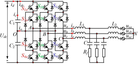
FIGURE 1. Structure diagram of three-level grid-connected NPC converter with LCL filter.
A single-phase model is taken for analysis as shown in Figure 2A, where ii is the inverter-side current, ig is the grid-side current, and ic is the current flowing through the filter capacitor C. The converter’s output voltage is equivalent to the sum of the fundamental voltage and the harmonic voltage; ux and uH represent the fundamental and harmonic components, respectively; and uON represents the voltage difference between point N and midpoint O, whose value is obtained by Eq. 1. Here, Sx represents the switching function of phase x:
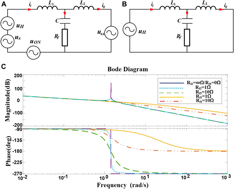
FIGURE 2. Equivalent model and Bode diagram of the LCL filter. (A) Basic equivalent model of series resistance. (B) High-frequency equivalent model of series resistance. (C) Bode diagram of LCL filter with series (Rf1) or parallel resistor (Rf2) on the capacitor.
The high-frequency equivalent model of the LCL filter is obtained by ignoring the harmonic component in ig, as shown in Figure 2B. In this linear system, the relationship between the grid-side current and the inverter-side voltage and between the grid-side current and inverter-side current is obtained according to the superposition theorem as follows:
The relationship between ig and UH can be seen in the above equations, including an integral term, a zero point, and a quadratic term. Thus, the conventional LCL transfer function has a resonant peak at zero point, causing a stability problem, but the high-frequency attenuation rate reaches −60 dB/dec. Then, the angular frequency of the system undamped oscillation ωresand the damping ratio ζ can be determined as follows:
The zero point of the LCL filter system is calculated as ωz = 1/(RC), and the relationship between the undamped oscillation angular frequency and the zero point can be determined as
Based on Eqs. 2, 5, relist the functional relationship between ig and UH as follows:
In summary, the external characteristics of the passive damping LCL filter are determined by L1 + L2, the damping coefficient, and the undamped oscillation angular frequency (Zheng et al., 2019).
2.2 Topology Contrast
The direct measure of passive damping to eliminate LCL resonance peaks is to connect inductor and capacitor elements in series or in parallel. Then, six methods are classified based on the position of the added devices (Kim and Kim, 2019). Adding a resistor directly at the position of the inductor element obviously affects the harmonics' attenuation ability. Therefore, it is better to connect the resistor in series (Figure 1 and Eq. 2) or in parallel to the capacitor. The transfer function of the parallel resistor at the capacitor position is listed as follows:
Figure 2C shows the Bode diagram of the LCL filter with a series or parallel resistor on the capacitor. Comparing the Bode diagram and the transfer functions between Eq. 2 and Eq. 7, it can be found that the series resistor causes the branch circuit to reduce the attenuation ability of high-frequency harmonics, whereas the parallel resistor does not affect the attenuation ability of high-frequency or low-frequency harmonics, but it bears the equivalent voltage on the capacitor causing greater system loss. Comparing two passive damping strategies, this study chooses the capacitor series resistor method due to its lower extra loss of the system.
Four improvement methods and their frequency characteristics (Xiao et al., 2018) are compared to solve the problem that the passive damping method selected in this study increases the loss of the filter system, as shown in Figure 3. From the comparison between the Bode diagram and Table 1, it can be seen that the improved topology shown in Figure 3A has improved both in terms of system loss and design simplicity. By connecting a small Lf in parallel with Rf (Wang et al., 2018), the impedance of Lf connected in parallel at the fundamental frequency is much less than Rf. The low impedance becomes the main current flow path so that the fundamental wave loss on Rf is reduced, and the parallel relationship between the small inductor and the resistor at a high frequency reduces the total impedance of the branch and the extra loss of the system.
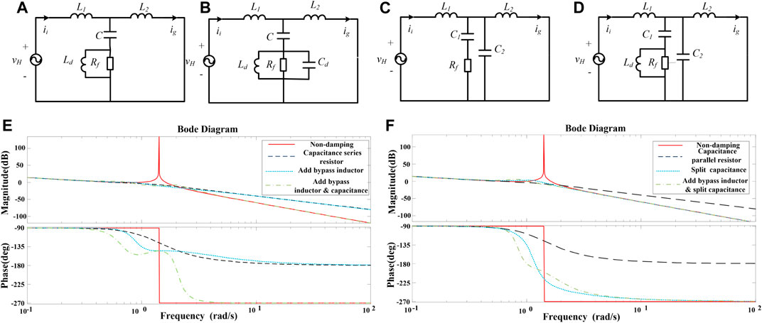
FIGURE 3. Equivalent model and Bode diagrams of four improved topologies. (A) Bypass inductor. (B) Bypass inductor plus capacitors. (C) Split capacitors. (D) Split capacitor plus bypass inductor. (E) Bypass elements. (F) Split capacitor.
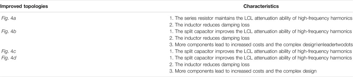
TABLE 1. The characteristics of four improved topologies.
2.3 The Mathematical Model of the System
According to the passive damping improved topology, is defined as the impedance ratio of Lf to Rf at the switching frequency, as shown in Eq. 8, and the transfer function of the system is shown in Eq. 9:
3 Interrelationship Between Parameters of LCL Filter
3.1 Constraints on Capacitor C and Total Inductor LT
In the design process of the LCL filter, first, determine the size of capacitor C and inductor LT. When the filter system is working normally, C has a high impedance characteristic in the low-frequency band and a low impedance characteristic in the high-frequency band. Under the same filtering effect, using a larger C reduces the used total inductor value (Beres et al., 2016b). However, an excessive C value increases the reactive current flowing into the capacitor and reduces the power factor and the system efficiency. The upper limit of C should be calculated based on the fundamental capacitive reactive power allowed by the system (Kumar et al., 2020).
When designing the inductor, C and Rf branches are usually considered open circuits so that the effect of the LCL filter is equivalent to that of an L-type filter with a total inductor of LT, which is convenient for parameter design. The design criteria of LT should minimize the current harmonics and meet the requirements of fast current tracking, the ripple requirements of the grid-connected current determine the lower limit of LT, and its dynamic requirements determine the upper limit of the inductor value.
3.2 Ratio k (L1/LT)
One of the goals of the LCL filter design is to reduce the size of passive components as much as possible, while ensuring that sufficient harmonic attenuation and reactive power are compensated by the filter. According to the analysis of Eqs. 3, 4, under the premise of determining parameters LT and C, the proportional relationship between two inductor values also affects the angular frequency of the undamped oscillation of the system ωres. Hence, it is necessary to carry out research on the proportional relationship between the inductors:
where k is the proportion of the inductor on the inverter side.
Then, the undamped oscillation frequency fres of the LCL filter is expressed as
Figure 4A is a diagram of the relationship between fres and k at undamped oscillation frequency, which shows that the resonance frequency is the lowest when k is 0.5.
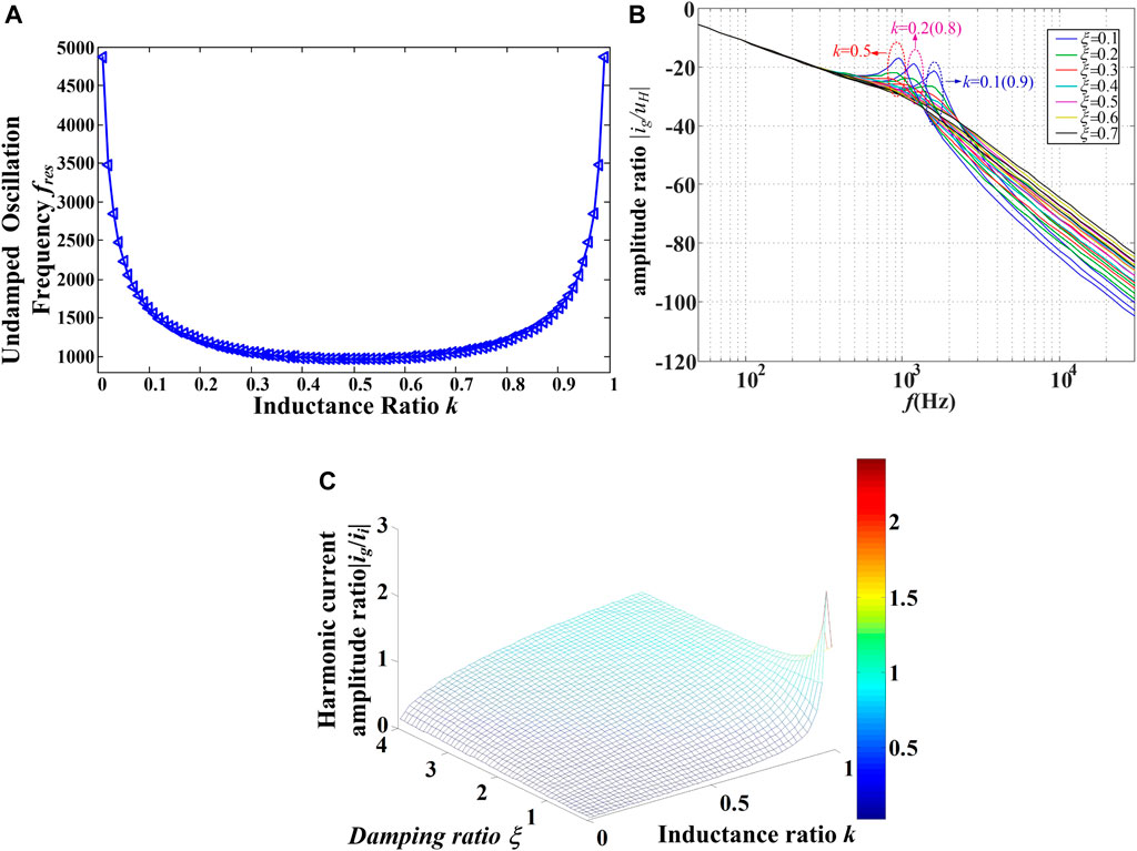
FIGURE 4. Diagram of the relationship among different parameters. (A) undamped oscillation frequency fres and inductor ratio k. (B) Amplitude ratio |ig/uH| capacitors. (C) Amplitude ratio |ig/ii|.
According to the relationship of Eqs. 3, 4, 10, 11 is transformed into the expression of ωres, ξ, and k:
The equivalent switching frequency fs is set to 3 kHz as shown in Figure 4B, Assuming that the equivalent switching frequency fs is 3 kHz, the value of ξ changes from 0.1 to 0.7, and k is 0.1 (0.9), 0.2 (0.8) and 0.5, respectively, the amplitudes of ig and Uh are shown in Figure 4B. The closer k is to 0.5, the lower the resonance frequency of the LCL filter is and the better the filtering effect on the higher harmonics generated by the modulation strategy is. The larger ξ is, the better the suppression effect of the resonance peak is. However, the increase in ξ makes the LCL filter’s attenuation effect on high-frequency ripple worse. Figure 4C shows the relationship between the ratio of ig to the absolute value of ii and k or ξ. From Figure 4C, it can be found that when k and ξ are small, the value of |ig/ii| is also small. When k or ξ is large, the value of |ig/ii| is also large, especially when k is close to 1 and ξ is close to 0, and |ig/ii| may even be greater than 1. At this time, the harmonics injected by the LCL filter into the grid are greater than those of the converter side. The function of the LCL filter changes from filtering out the harmonic voltage and current, in a general sense, to amplifying harmonic currents.
3.3 Relation Between Ratio k and Other Key Parameters
Based on Eqs. 3, 4, it can be seen that k and Rf also affect each other.
Figure 5 shows the relationship between the power loss of the LCL filter, the inductor proportional coefficient k, and Rf. Figure 5 assumes that the harmonic energy is concentrated at the switching frequency. The larger the value of k, the smaller the loss. When the value of k is the same, the fundamental loss and switching subharmonic loss first increase and then decrease with Rf. Through the above analysis, the relationship among the ratio of correlation coefficient of the system, k, and ξ is obtained. The values of k and ξ that optimize all system performance cannot be found. Thus, a compromise should be made in the practical design, according to the operation situation.
1) When k = 0.5, fres is minimal. When k approaches 0(1), fres gets larger.
2) As ξ increases, the smaller the resonance peak is, the larger the high-frequency attenuation is and vice versa.
3) As k or ξ increases, |ig/ii| gets larger; k is the main influencing factor of |ig/ii|.
4) As k increases, damping resistor power loss (Ploss) gets smaller. As ξ increases, Ploss increases firstly and then decreases*.
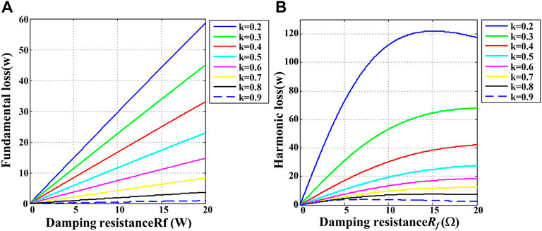
FIGURE 5. Relation between power loss of Rf, inductor ratio k, and resistor of Rf. (A) Fundamental wave loss. (B) Harmonic loss.
*ξ is proportional to Rf when k is determined.
3.4 Impedance Ratio α
It is obtained from Part B that the system reaches the lowest resonant frequency when k is 0.5, and Bode diagrams of each transfer function are obtained under the condition that Rf is a fixed value and α is different based on Eq. 8, as shown in Figures 6A–C.
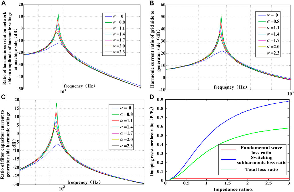
FIGURE 6. Bode diagrams and damping resistance loss ratio of the LCL filter. (A) Ratio of grid-side harmonic current to machine-side amplitude of harmonic voltage. (B) Ratio of grid-side harmonic current to machine-side harmonic current. (C) Ratio of filter capacitor current to machine-side harmonic voltage. (D) Damping resistance loss ratio of LCL filter with damping inductance and without damping inductance.
From Figures 6A,B, it can be seen that the LCL filter with the damping inductor has a lower resonance frequency and better high-frequency harmonic filtering effect than that without the damping inductor. However, it also has the disadvantage of large gain at a resonance frequency. Figures 6A–C show that the harmonic current gain at the resonance frequency decreases as α increases. Because the harmonics are mainly concentrated in the part above the switching frequency, this disadvantage has little effect on the filtering effect. It can be seen from Figure 6C that the introduction of Lf basically does not affect the fundamental wave current flowing into C, and in terms of switching sub-harmonic currents, the introduction of the damping inductor reduces the flow of C. The switching sub-harmonic current is slightly smaller than the switching sub-harmonic current without the damping inductor.
Figure 6D shows the damping resistance loss ratio of the LCL filter with and without damping inductance. It can be seen from Figure 6D that, as α increases, both the fundamental wave loss ratio and the switching harmonic loss increase because Lf has a weak impedance to the fundamental wave, so the fundamental wave current flowing through C basically flows into Lf, and the fundamental wave loss on the damping resistor is small. As α increases, Lf also increases accordingly, which increases the system cost. Therefore, this study chooses α = 1. At this time, the loss on the damping resistor of the LCL filter with damping inductor is 1/4–1/3 of that without the damping inductor.
4 Determination of Filter Parameters
Based on the analysis process of Part 3, the design parameters of the LCL filter k and α is set to 0.5 and 1. Under this condition, the resonant system frequency is the lowest and the damping loss is the smallest.
Figure 7 presents the algorithm proposed in this study. The LCL filter is operated as an integrated filter unit instead of separately considering the effects of the grid-connected and the inverter sides. The steps of this design are simple and convenient for adjustment. In addition, this design satisfies the most filter requirements.
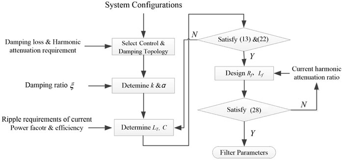
FIGURE 7. The design process of the LCL filter, where Y and N stand for yes and no, respectively.
The specific operation steps are as follows:
1) Select the basic damping and improved topology.
2) Determine k and α based on Parts 3.1 and 3.4.
3) Design LT and C in the LCL filter.
4) Determine the Rf range achieved by the maximum attenuation ratio k and α at the resonant angular frequency and the equivalent switching angular frequency.
5) Properly select the inductor value and then solve the actual inductor value on the grid-connected and the inverter sides.
6) Perform a physical design based on harmonic attenuation analysis and THD analysis of the filter.
4.1 Calculating the Total Capacitor C
As power factor and efficiency lead to problems in the system, the upper limit of C needs to be considered:
In Eq. 13, Qc is the fundamental capacitive reactive power allowed by the system, Prated is the total power of the system, b is the percentage of capacitive reactive power in the total power, ω0 is the grid voltage angular frequency, and Uline is the grid line voltage valid value.
4.2 Calculating the Total Inductor LT
The lower limit of LT is determined by the ripple requirements of the grid-connected current, and its upper limit is determined by dynamic requirements.
4.2.1 Ripple Requirements of Current
Figure 8A shows a diagram of the output phase voltage pulse waveform near the peak of the a-phase current of the three-level converter. At this time, the a-phase voltage of power grid reaches its maximum Em (system power factor is 1). According to the basic principle of the circuit, the peak-to-peak values of Δipp1 and Δipp2 during the rise and fall of the inductor current are obtained:
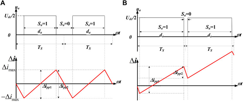
FIGURE 8. Corresponding situation of phase voltage pulse and phase current ripple (phase a). (A) ia = imax. (B) imax = 0.
Sb1, Sb0 and Sc1, Sc0 are the switching states of phases b and c when the switching states of phase a are 1 and 0, respectively. In a three-phase symmetric system, it can be known from the circuit theory that when a certain voltage or current reaches its maximum value, the other two phase voltages or currents are −0.5 times the maximum value. The deduction is as follows:
In order to maintain the stability of the system, Δipp1 should be equal to −Δipp2. Then, based on Eqs. 14, 15, the maximum ripple current Δimax of phase a can be obtained as follows:
When the maximum ripple required by the system is IrippleM, the total inductor LT needs to meet
4.2.2 Requirements of Current Tracking Rapidity
Figure 8B is the diagram of output phase voltage pulse and the a-phase ripple current near the zero-crossing point of the a-phase current of the three-level converter. According to the basic principle of the circuit, the peak-to-peak value Δipp1 and Δipp2 during the rise and fall of the inductor current are obtained:
According to the circuit theory, the voltages of phases b and c are −
In order to meet the needs of fast current tracking, Δipp1 and Δipp2 need to meet the following relationship:
As da is approximately equal to 1 at the zero-crossing point of the a-phase current, the total inductor LT needs to meet
Based on the above analysis, the total inductor of the LCL filter is obtained based on the ripple current and current tracking conditions, as shown in Eq. 22. Due to cost and volume, LT should be as close to its lower limit as possible in practical applications of high-voltage and high-power systems:
4.3 Damping Resistor Rf
After the range of C and LT are determined, Rf is designed according to the correlation degree of the parameters in part 3.
1) The lower limit is designed according to the attenuation effect at the resonant angular frequency from Eq. 9, at the value of ωres, and the amplitude ratio of ig to uH is obtained as
If the system requires the maximum attenuation at ωres to be κ (0 < κ < 1), then
Based on the above derivation, the lower limit value that Rf should meet when k = 0.5 is calculated:
2) Determine the upper limit value according to the current harmonic attenuation ratio from Eq. 9, at ωres, and the amplitude ratio of ig to ii is obtained as
When k = 0.5, ωres ≥ 2ωres, if the system requires the current harmonic attenuation ratio at the equivalent switching frequency ωs to be the maximum γ (0 < γ < 1), then
Considering the attenuation effect at the resonance frequency and the current harmonic attenuation ratio, the upper and lower limits of Rf is obtained as follows:
4.4 Design Example
In order to verify the design method proposed above, the minimum resonant frequency and the system loss are considered to design the LCL filter under the parameters as shown in Table 2. The overall design steps are as follows.
1) Control grid-side current and obtain the topology of series resistor with small parallel inductor shown in Figure 3A, which suppresses the resonant peak and reduces loss of the resistor.
2) Set k and α as 1, according to the principle of the minimum resonant frequency.
3) Determine the range of capacitor and total inductor according to Eqs. 13, 22, and determine the range of added Rf, based on the harmonic attenuation ratio.
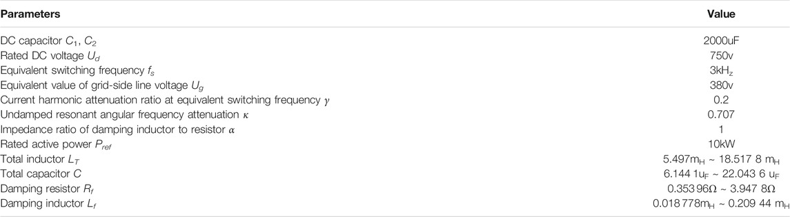
TABLE 2. System parameters.
5 Simulation and Experimental Results
Based on the previous theoretical analysis, selecting a decimal point in device selection increases the difficulty of industrial design. Therefore, integer parameters are selected and the three-level NPC type SVG simulation and experimental model is established in MATLAB to verify the analysis of this study. The circuit schematic diagram is shown in Figure 1, and system parameters and LCL filter element parameters are shown in Table 2. LT = 6 mH, C = 18 uF, Rf = 1Ω, and Lf = 0.08 mH are selected, and the simulation sampling time is 2e–6s. Figure 9A shows the simulation waveforms Ua, ig, ii, and iR flowing through Rf during full power operation under different conditions. All the simulation results of different LCL filter parameters of each figure are shown in Table 3.
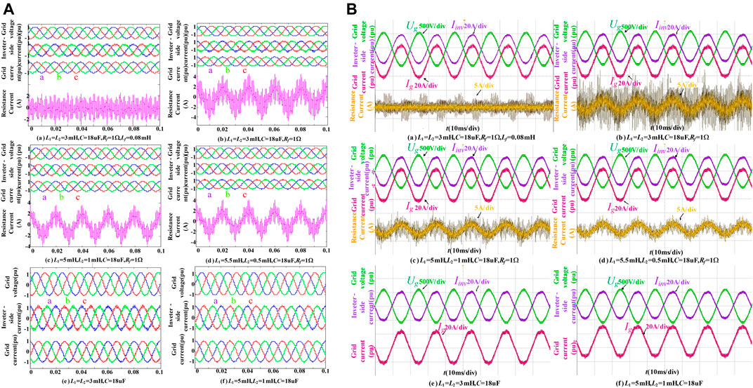
FIGURE 9. Simulation and experimental results of the LCL filter under different key parameters (A) simulation result (B) experimental result.
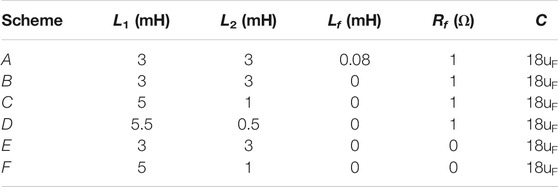
TABLE 3. Comparison of systerm parameters.
Table 4 is a quantitative comparison of the simulation and experimental results of different filter parameters. It mainly presents three aspects of the filter performance of the system, the total harmonic distortion (THD) of the ii and that of ig in the six cases, and |ig/ii| and Ploss. From the simulation results of the above six different situations, it can be seen that the LCL filter design method based on the optimization of resonance frequency proposed in this study has advantages of small harmonic current into the grid and low damping resistor loss.
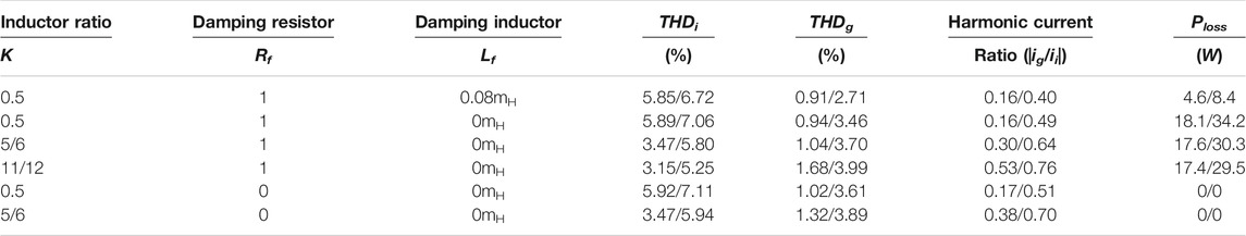
TABLE 4. Simulation/experimental results comparison of LCL filter under different key parameters.
Specifically, comparing Figure 9A with the relevant content in Table 4, it can be found that when the inductor ratio is the same, the existence of the damping resistor reduces the THD of the grid current because it suppresses the occurrence of resonance, and the existence of damping inductor reduces the loss of the damping resistor to about 1/4 of the original value, which is consistent with Figure 6D. Comparing the three graphs on the right of Figure 9B with Table 4, it can be found that when the damping resistor is the same, the closer the inductor ratio is to 0.5, the better the filtering effect is, which is consistent with Figure 4A and Figure 4B. The larger the inductor ratio is, the greater the harmonic current amplitude ratio is, which is consistent with Figure 4C. The larger the inductor ratio is, the smaller the damping resistor loss is, which is consistent with Figure 6D.
Figure 9B shows the experimental results of corresponding waveforms of grid voltage Uca, inverter-side current iib, grid-side current igb, and current iRb flowing through the damping resistor when the three-level SVG system under different LCL filter parameters is running at full power. Table 5 shows the relevant data analysis. Because the actual grid voltage contains about 2% of low-order harmonics, the grid-side current, the inverter-side current THD, and the damping resistor power are all larger than the simulated values. It can be seen from the above analysis that the theoretical analysis and simulation results are similar. Figures 10A,B show the gap between the simulation data and the real experimental results. Considering the influence of background harmonics of about 2%, the theory proposed in this study is verified by the above simulation and experimental results.
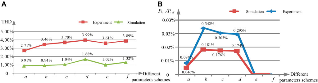
FIGURE 10. Simulation and experimental results of THD and Ploss/Pref (A) THD result (B) Ploss/Pref result.
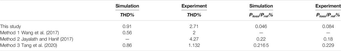
TABLE 5. Simulation and experimental values of THD and loss ratio with different methods.
∗In the case of e or f in Figure 10B, the damping loss is not discussed without adding a damping resistor.
In order to further verify the optimization algorithm, the key parameters of the grid-side current THD and those of damping resistor loss are compared with the methods proposed in the existing literature, as shown in Table 5. For the parameter THD, it can be seen that there is little difference from the simulation value of Method 3 (Tang et al., 2020). Nevertheless, due to the high harmonic content of the power grid under laboratory conditions, the experimental value is larger and the THD part of the side current has a certain effect. Compared with Method 3 in terms of THD, it can be found that the method proposed in this study is not much different, which may be due to the simulation parameter setting and measurement error. For resistor loss ratio parameters Ploss/Pref, except for Method 1 (Wang et al., 2017) that presents no measurement data, the proposed optimization method is different from the other existing methods. It makes much noticeable improvement in reducing the loss of the damping resistor.
5.1 Conclusion
Focusing on the correlation degree of system parameters is important for realizing a high-efficiency LCL filter. This study proposes a bypass inductor type LCL filter parameter optimization for a three-level grid-connected converter. In this design, the inductance ratio k and impedance ratio α are taken as the key variables, and it is found that the optimal undamped resonant frequency is achieved and the system loss is reduced when both κ and α equal 1 in the modified, passive damping topology of parallel inductors. In addition, the design provides a simple parameter design system. Based on the reactive power limit and current ripple, the range of parameters is calculated clearly. The design has great theoretical significance and application value through the simulation and experimental results to verify the validity of the proposed theory, which is especially suitable for large-power and low-switching frequency fields.
Data Availability Statement
The original contributions presented in the study are included in the article/Supplementary Material, further inquiries can be directed to the corresponding author.
Author Contributions
LN is responsible for the overall structure and revision. ZS, XZ, and ZA are responsible for writing and the simulation experiment. YZ and LJ are responsible for the evaluation and improvement of the paper.
Funding
This work was supported in part by National Natural Science Foundation of China (52177193); Key Research and Development Program of Shaanxi Province (2022GY-182);China Scholarship Council (CSC) State Scholarship Fund International Clean Energy Talent Project (Grant No. (2018)5046,(2019)157); Open Research Fund of Jiangsu Collaborative Innovation Center for Smart Distribution Network, Nanjing Institute of Technology (XTCX202107).
Conflict of Interest
The authors declare that the research was conducted in the absence of any commercial or financial relationships that could be construed as a potential conflict of interest.
Publisher’s Note
All claims expressed in this article are solely those of the authors and do not necessarily represent those of their affiliated organizations or those of the publisher, the editors, and the reviewers. Any product that may be evaluated in this article, or claim that may be made by its manufacturer, is not guaranteed or endorsed by the publisher.
References
Albatran, S., Koran, A., Smadi, I. A., and Ahmad, H. J. (2018). Optimal Design of Passive RC-Damped LCL Filter for Grid-Connected Voltage Source Inverters. Electr. Eng. 100, 2499–2508. doi:10.1007/s00202-018-0725-5
Ben Saïd-Romdhane, M., Naouar, M. W., Slama-Belkhodja, I., and Monmasson, E. (2017). Robust Active Damping Methods for LCL Filter-Based Grid-Connected Converters. IEEE Trans. Power Electro. 32, 6739–6750. doi:10.1109/TPEL.2016.2626290
Beres, R. N., Wang, X., Liserre, M., Blaabjerg, F., and Bak, C. L. (2016a). A Review of Passive Power Filters for Three-phase Grid-Connected Voltage-Source Converters. IEEE J. Emerg. Sel Top. Power Electron. 4 (1), 54–69. doi:10.1109/jestpe.2015.2507203
Beres, R. N., Wang, X., Blaabjerg, F., Liserre, M., and Leth Bak, C. (2016b). Optimal Design of High-Order Passive-Damped Filters for Grid-Connected Applications. IEEE Trans. Power Electro. 31, 2083–2098. doi:10.1109/tpel.2015.2441299
Bosch, S., Staiger, J., and Steinhart, H. (2018). Predictive Current Control for an Active Power Filter with LCL-Filter. IEEE Trans. Ind. Electro. 65, 4943–4952.doi:10.1109/TIE.2017.2772176
Falkowski, P., and Sikorski, A. (2018). Finite Control Set Model Predictive Control for Grid-Connected AC–DC Converters with LCL Filter. IEEE Trans. Ind. Electro. 65 (4), 2844–2852. doi:10.1109/tie.2017.2750627
Guo, X. Q., Wu, W. Y., and Gu, H. R. (2010). Modeling and Simulation of Direct Output Current Control for LCL-Interfaced Grid-Connected Inverters with Parallel Passive Damping. Simulation Model. Pract. Theor. 18 (7), 946–956. \\enleadertwodots. doi:10.1016/j.simpat.2010.02.010
Guzman, R., de Vicuña, L. G., Castilla, M., Miret, J., and de la Hoz, J. (2018). Variable Structure Control for Three-phase LCL-Filtered Inverters Using a Reduced Converter Model. IEEE Trans. Ind. Electro. 65, 5–15. doi:10.1109/tie.2017.2716881
He, J., Yun, W. L., Xu, D., Liang, X., Liang, B., and Wang, C. (2017). Deadbeat Weighted Average Current Control with Corrective Feed-Forward Compensation for Micro-grid Converters with Nonstandard LCL Filter. IEEE Trans. Power Electro. 32 (4), 2661–2674. doi:10.1109/tpel.2016.2580005
Huang, S., Tang, F., Xin, Z., Xiao, Q., and Chiang Loh, P. (2019). Grid-Current Control of a Differential Boost Inverter with Hidden LCL Filters. IEEE Trans. Power Electro. 34, 889–903. doi:10.1109/tpel.2018.2817640
Jayalath, S., and Hanif, M. (2017). Generalized LCL-Filter Design Algorithm for Grid-Connected Voltage-Source Inverter. IEEE Trans. Ind. Electro. 64 (3), 1905–1915. doi:10.1109/tie.2016.2619660
Kim, Y. J., and Kim, H. (2019). Optimal Design of LCL Filter in Grid-Connected Inverters. Power Electron. IET 12 (7), 1774–1782. doi:10.1049/iet-pel.2018.5518
Kouchaki, A., and Nymand, M. (2018). Analytical Design of Passive LCL Filter for Three-phase Two-Level Power Factor Correction Rectifiers. IEEE Trans. Power Electro. 33, 3012–3022. \\enleadertwodots. doi:10.1109/tpel.2017.2705288
Kumar, N., Mohamadi, M., and Mazumder, S. K. (2020). Passive Damping Optimization of the Integrated-Magnetics-Based Differential-Mode Ćuk Rectifier. IEEE Trans. Power Electro. 35, 10008–10012. doi:10.1109/tpel.2020.2981918
Liserre, M., Blaabjerg, F., and Hansen, S. (2005). Design and Control of an LCL-Filter-Based Three Phase Active Rectifier. IEEE Trans. onIndustry Appl. 41 (5), 1281–1290. doi:10.1109/tia.2005.853373
Liu, B., Li, Z., Chen, X., Huang, Y., and Liu, X. (2018). Recognition and Vulnerability Analysis of Key Nodes in Power Grid Based on Complex Network Centrality. IEEE Trans. Circuits Syst. Express Briefs 65 (3), 346–350. doi:10.1109/tcsii.2017.2705482
Liu, B., Li, Z., Dong, X., Yu, S. S., Chen, X., Oo, A. M. T., et al. (2021). Impedance Modeling and Controllers Shaping Effect Analysis of PMSG Wind Turbines. IEEE J. Emerg. Sel. Top. Power Electron. 9 (2), 1465–1478. doi:10.1109/jestpe.2020.3014412
Su, M., Cheng, B., Sun, Y., Tang, Z., Guo, B., Yang, Y., et al. (2019). Single-Sensor Control of LCL-Filtered Grid-Connected Inverters. IEEE Acess 7, 38481–38494. doi:10.1109/access.2019.2906239
Tang, W., Ma, K., and Song, Y. (2020). Critical Damping Ratio to Ensure Design Efficiency and Stability of LCL Filters. IEEE Trans. Power Electro. 36, 315–325. doi:10.1109/TPEL.2020.3000897
Wang, X., Blaabjerg, F., and Loh, P. C. (2017). Passivity-Based Stability Analysis and Damping Injection for Multiparalleled VSCs with LCL Filters. IEEE Trans. Power Electro. 32, 8922–8935. doi:10.1109/tpel.2017.2651948
Wang, B., Shen, Z., Hong, L., and Jianhui, H. (2018). Linear ADRC Direct Current Control of Grid-Connected Inverter with LCL Filter for Both Active Damping and Grid Voltage Induced Current Distortion Suppression. IET Power Electro. 11 (11), 1748–1755. doi:10.1049/iet-pel.2017.0787
Wei, M., and Gao, C. (2017). “Comparison and Analysis of a Novel Passive Damping for LCL Filtered Voltage Source Inverters,” in 2017 20th International Conference on Electrical Machines and Systems (ICEMS), Sydney, NSW, 1–5.
Xia, W., and Kang, Js. (2017). Stability Analysis of Static Synchronous Compensator in LCL Distribution Network Considering the Influence of Digital Control Delay. Trans. China electro Tech. Soc. 32 (14), 205–216. doi:10.19595/j.cnki.1000-6753.tces.L70752
Xiao, Z., Li, T., Xian, J., Zhang, H., Ma, Z., and Kang, J. (2018). Direct Grid-Side Current Model Predictive Control for Grid-Connected Inverter with LCL Filter. IET Power Electro. 11 (15), 2450–2460. doi:10.1049/iet-pel.2018.5338
Xiong, L., Liu, X., Liu, Y., and Zhuo, F. (2020). Modeling and Stability Issues of Voltage-Source Converter Dominated Power Systems: a Review. CSEE J. Power Energy Syst.. doi:10.17775/CSEEJPES.2020.03590
Xiong, L., Liu, X., Zhang, D., and Liu, Y. (2021). Rapid Power Compensation Based Frequency Response Strategy for Low Inertia Power Systems. IEEE J. Emerging Selected Top. Power Electro. 9 (4), 4500–4513. doi:10.1109/jestpe.2020.3032063
Xiong, L., Liu, X., and Liu, Y. (2021). Decaying DC and Harmonic Components Detection for Absorbing Impact Load Currents in Weak Grids. IEEE Trans. Power Deliv. 36 (3), 1907–1910. doi:10.1109/tpwrd.2020.3038077
Yao, W., Yang, Y., Zhang, X., Blaabjerg, F., and Chiang Loh, P. (2017). Design and Analysis of Robust Active Damping for LCL Filters Using Digital Notch Filters. IEEE Trans. Power Electro. 32 (3), 2360–2375. \\enleadertwodots. doi:10.1109/tpel.2016.2565598
Young, H. A., Marin, V. A., Pesce, C., and Rodriguez, J. (2020). Simple Finite-Control-Set Model Predictive Control of Grid-Forming Inverters with LCL Filters. IEEE Access 8 (8), 1246–1256. \\enleadertwodots. doi:10.1109/access.2020.2991396
Zeng, Z., Xu, S., Ran, L., and Chen, M. (2016). Active Dampers and Control for Resonant Suppression of AC Micro-Grid. Power Autom. equip. 36 (03), 15–20. doi:10.16081/j.issn.1006-6047.2016.03.003
Zhang, C., Li, Y., Jia, C., Fu, H., Zhang, X., Zhang, H., et al. (2021). Direct Active Damping Control for Grid-Connected AC/DC Converter with LCL Filter Using Augmented Look-Up Tab. IET Power Electro. 14 (6), 1089–1101. doi:10.1049/pel2.12090
Keywords: LCL filter, passive damping, stability, voltage-source converters, bypass inductor
Citation: Li N, Zhang S, Xiao Z, An Z, Zhang Y and Jiang L (2022) Bypass Inductor Type LCL Filter Parameter Optimization for Three-Level Grid-Connected Converter. Front. Energy Res. 10:852046. doi: 10.3389/fenrg.2022.852046
Received: 10 January 2022; Accepted: 09 February 2022;
Published: 15 March 2022.
Edited by:
Liansong Xiong, Nanjing Institute of Technology (NJIT), ChinaReviewed by:
Shuzheng Wang, Nanjing Institute of Technology (NJIT), ChinaDongbo Guo, Northeast Electric Power University, China
Peng Fang, University of Minnesota Duluth, United States
Copyright © 2022 Li , Zhang , Xiao , An, Zhang and Jiang. This is an open-access article distributed under the terms of the Creative Commons Attribution License (CC BY). The use, distribution or reproduction in other forums is permitted, provided the original author(s) and the copyright owner(s) are credited and that the original publication in this journal is cited, in accordance with accepted academic practice. No use, distribution or reproduction is permitted which does not comply with these terms.
*Correspondence: Lin Jiang, TC5KaWFuZ0BsaXZlcnBvb2wuYWMudWs=