 Yuan Ma
 Tianhui Fan
- School of Civil Engineering and Transportation, South China University of Technology, Guangzhou, China
Due to the existence of rotor and tower, the floating offshore wind turbine (FOWT) is subjected to greater wind heeling moment than the conventional floating platform, which would cause significant pitch motion and bring great challenge to the structural safety and power generating efficiency. Moreover, the dynamic cable used for power transmission is sensitive to the horizontal motion of floating platform. Thus, it is essential to inhibit the pitch and horizontal motions of FOWT. The FOWT is connected to the seabed by a mooring system to resist the motions, while the conventional mooring system mainly resists the horizontal motion. In this article, an innovative type of mooring system was proposed to resist the pitch and horizontal motions simultaneously, by dividing the fairleads into two groups at different depths. The motion responses and structural loads of FOWTs were calculated and compared under the effects of the conventional and innovative mooring systems. In addition, the restoring forces and moments of two mooring systems were also given to better verify the motion-inhibiting performances. According to the results, the innovative mooring system was able to significantly reduce the pitch and surge motions of FOWT.
Introduction
With the development of offshore wind power, it is inevitable for the application of floating offshore wind turbines (FOWTs). The FOWT is less sensitive to the environmental conditions, such as the water depths or seabed conditions, and has better applicability in the deep sea area from the prospective of safety and economy (Lee and Zhao, 2020).
Due to the existence of rotor and tower, the FOWT is subjected to greater wind heeling moment than the conventional floating platform. The wind heeling moment would cause significant pitch motion, which influences the power generating efficiency and structural safety (Ma et al., 2019; Ma et al., 2021). Shen et al. (2018) investigated the effects of pitch motion from the perspective of unsteady aerodynamics, through a lifting surface method with free wake model. According to the results, the pitch motion would generate highly unsteady aerodynamic behavior, which influences the loads on the wind turbine and global motion responses. Moreover, it was found in the research that the average power generating efficiency increased with the frequency of pitch motion, while the average aerodynamic thrust did the opposite. Karimian et al. also studied the influences of pitch motion input on aerodynamic characteristics, accounting for the effects of blade pitch control system (KarimianAliabadi and Rasekh, 2020). Compared with the fixed-type offshore wind turbine, the average aerodynamic thrust coefficients of FOWT were reduced in the full wind speed range. In addition, the average power generation efficiency under the conditions of low tip speed ratio (TSR) was also reduced, compared with the fixed type, while the cases for high TSR were the reverse. Xiao et al. analyzed the effects of pitch motion induced by ocean swell waves on the wake flow and power extraction of wind turbine rotor with a hybrid numerical model (Xiao and Yang, 2019). The results were compared with the fixed-type offshore wind turbine and showed that the pitch motion caused significant oscillations of vertical flow velocity and Reynolds number.
Based on the effects of pitch motion on FOWT, there were many solutions proposed to reduce the pitch motion. Lackner et al. reduced the pitch motion of FOWT by designing a new variable collective blade pitch controller (Lackner, 2009). However, Larsen et al. found that the blade pitch control strategy could induce negative damping effects on pitch motion under certain conditions (Larsen and Hanson, 2007). Therefore, Iino et al. (2012) improved the control strategy to reduce the effects of negative damping and verified the performance of control system by an experiment. Guo et al. (2012) also investigated the effects of individual blade pitch controller on global pitch motion based on a proportional–integral–derivative controller. The analytical results showed that the individual blade pitch controller was able to reduce the global pitch motion effectively. Based on the aforementioned research, it could be confirmed that the global pitch motion could be reduced by improving the blade pitch control algorithm. However, it might be unsteady under the complicated environmental conditions and reduce the power extraction of wind turbine.
Moreover, the power generated by FOWT is transmitted onshore by a dynamic cable, which is attached to the floating platform. The load distribution along the cable is determined by the horizontal location of FOWT. Therefore, the horizontal motion would have significant effects on the dynamic behavior of dynamic cable. Thies et al. (2017) studied the influences of environmental conditions on the mechanical loads and evaluated the potential failure modes of dynamic cable. It was found that the dynamic cable attached on the FOWT should maintain the S shape as much as possible to achieve proper load distribution along the cable. Taninoki et al. (2017) found that the mechanical stress on the dynamic cable system was mainly caused by the horizontal motions of FOWT, based on a case study of a hybrid-spar FOWT. In addition, the horizontal motion of FOWT and load distribution of dynamic cable under the failure of one mooring line were calculated and analyzed by Bae et al. (2017) and Li et al. (2018). The results showed that the dynamic cable could be disconnected.
Based on the aforementioned issues, it could be confirmed that the horizontal and pitch motions of FOWT need to be reduced for better dynamic performance. In this article, an innovative mooring system was proposed to reduce the horizontal and pitch motions of FOWT. To verify the motion inhibiting performance of the proposed mooring system, a conventional type of mooring system was used for comparison. The motion responses and structural loads of FOWT were calculated and compared under the effects of two mooring systems. Moreover, the restoring force and moment of two mooring systems were also given for verification. The coupled calculation in this article was completed with AQWA and the DLL file developed by Yang et al. (2020).
Mooring System
To verify the motion inhibiting performance of the proposed mooring system, the OC3-Hywind Spar and NREL 5 MW were employed for case study. The principal dimensions and reference coordinate system of OC3-Hywind Spar are shown in Figure 1 and Figure 2. The OXY plane coincided with the still water plane. The performance parameters of FOWT are given in Table 1 (Jonkman et al., 2009; Jonkman, 2010).
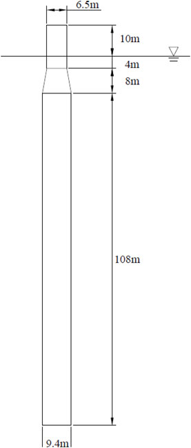
FIGURE 1. Principal dimensions.
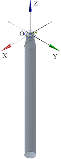
FIGURE 2. Reference coordinate system.
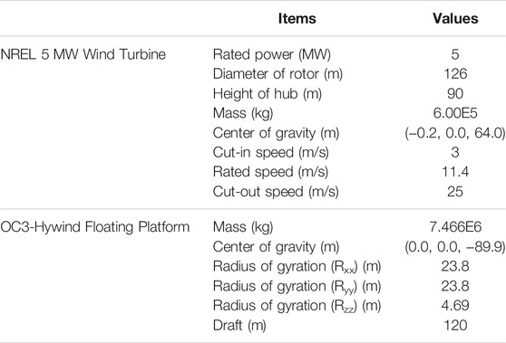
TABLE 1. Performance parameters of the FOWT
Different from the conventional type, the proposed innovative mooring system was able to inhibit the horizontal and pitch motions of FOWT simultaneously. The fairleads were divided into two groups, which were at different depths to generate greater pitch restoring moment while maintaining the horizontal restoring forces. The parameters of mooring lines are given in Table 2 and the layouts of two mooring systems are shown in Figure 3 and Figure 4. These two mooring systems both had 9 mooring lines. For the conventional type, the fairleads were put at the same depth (70 m). For the innovative type, the fairleads were, respectively, put at two different depths (10 m: Line Nos. 1, 3, 4, 6, 7, and 9; 120 m: Line Nos. 2, 5, and 8).
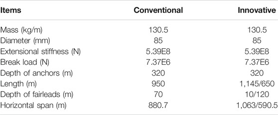
TABLE 2. Parameters of mooring lines
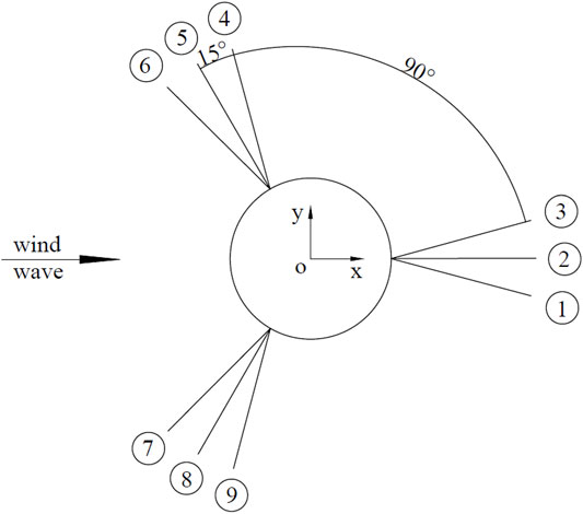
FIGURE 3. Top view of the mooring lines layout (the top views of two mooring systems are the same).
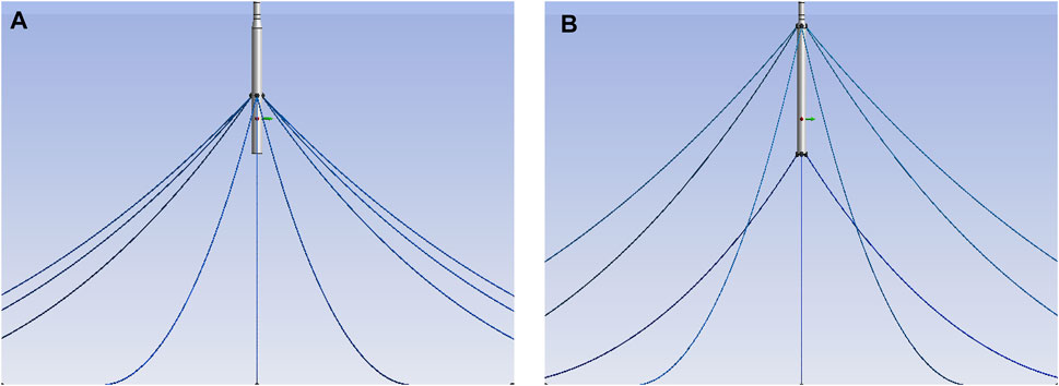
FIGURE 4. Two types of mooring systems. (A) Conventional. (B) Innovative.
Moreover, with the piecewise extrapolating method (Fan et al., 2014), the static restoring stiffnesses of two mooring systems in horizontal (surge), vertical (heave), and pitch directions are calculated and shown in Figure 5. It should be noticed that the horizontal displacement was positive along the X-axis and the global pitch angle used in the calculations was 0°. According to the results, the horizontal restoring stiffnesses of two mooring systems were basically equal and the vertical restoring stiffness of innovative mooring system was slightly greater than the conventional type. It was noticeable that the restoring stiffness of innovative mooring system in the pitch DOF was much greater than the conventional type, which meant that it could help to significantly reduce the pitch motion. In addition, although the horizontal restoring stiffnesses of two mooring systems were basically equal at the 0° pitch angle, the innovative mooring system could generate greater horizontal restoring stiffness taking advantage of the pitch motions, as elaborately introduced in Sections Motion Responses and Restoring Forces and Moments.
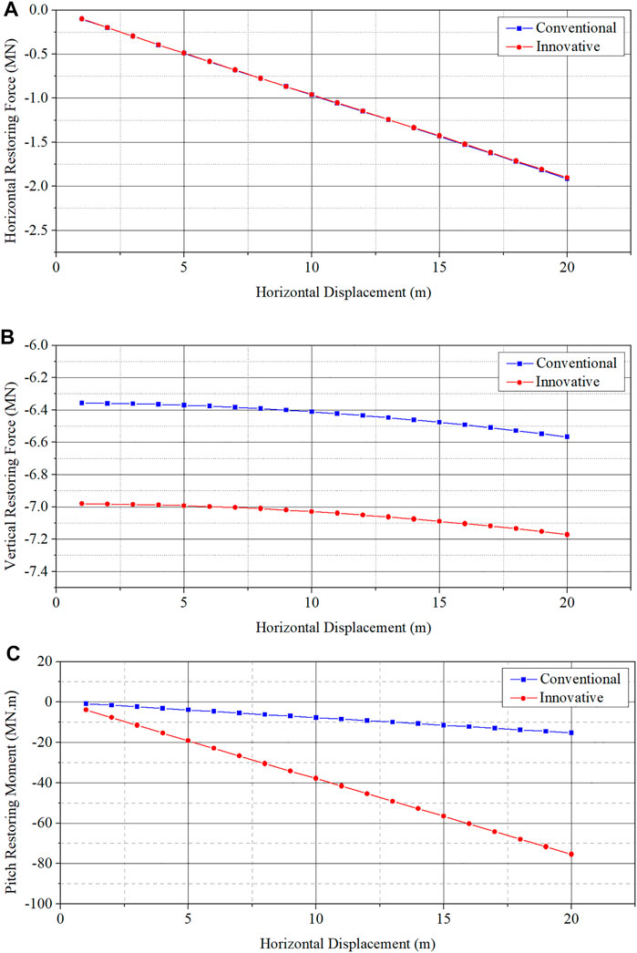
FIGURE 5. Static restoring force and moment. (A) Horizontal restoring force. (B) Vertical restoring force. (C) Pitch restoring moment.
Methodology
Frequency-Domain Analysis
The three-dimensional potential flow theory was used for the frequency-domain hydrodynamic analysis. The radiation and diffraction potentials could be obtained by solving the integral equation with flow field boundary conditions. Based on the velocity potential of flow, the first-order hydrodynamic force could be expressed as (ANSYS and AQWA, 2018)
where
The added mass and radiation damping of floating structure could be obtained by solving following equation (ANSYS and AQWA, 2018):
where
The motions of FOWT are significantly influenced by the second-order wave force. In this article, the second-order wave loads were mainly dominated by the mean drift force and difference frequency force, which were respectively calculated by the far-/near-field methods and full QTF method (ANSYS and AQWA, 2018).
Time-Domain Coupled Analysis
The FOWT is under the coupled effects of aerodynamic, hydrodynamic, and mooring loads simultaneously. Therefore, it is necessary to carry out the time-domain coupled analysis of FOWT. The hydrodynamic parameters have been obtained by the frequency-domain analysis.
The aerodynamic loads on wind turbine rotor could be obtained by blade element momentum (BEM) theory, which discretizes the blade into blade elements and calculates the aerodynamic loads on each element with the theorem of momentum. The aerodynamic thrust and torque on each blade element could be expressed as (Jonkman and Buhl, 2005)
where
The tension of mooring line could be calculated by the lumped-mass method to account for the dynamic effects, which discretizes the mooring line into Morison elements. The mass and applied/internal forces of each element are assembled on one point. The dynamic governing equation of mooring line element could be expressed as (ANSYS and AQWA, 2018)
where
The coupled motion responses of FOWT could be solved by the Cummins equation, expressed as follows (Cummins, 1962; ANSYS and AQWA, 2018):
where
The flowchart of time-domain coupled analysis is given in Figure 6 to better introduce this methodology.
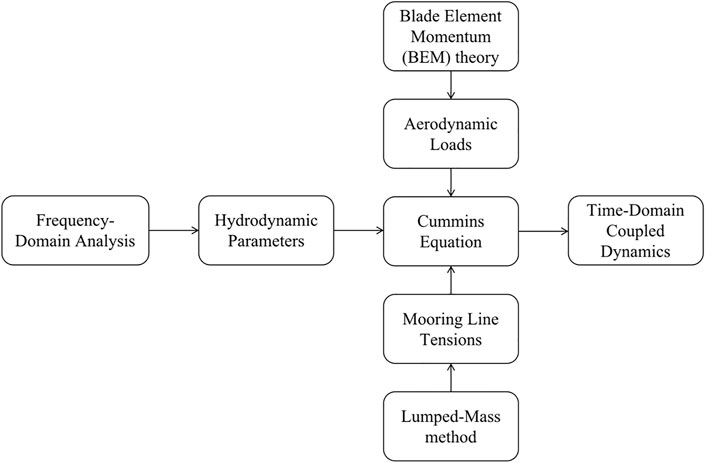
FIGURE 6. Flowchart of time-domain analysis methodology.
Structural Dynamics
Accounting for the elasticity and deflection, the blade and tower are modeled as beam model and discretized into elements. The dynamics could be governed by the following equation:
where
Results and Analysis
Model Validation
To verify the quality of hydrodynamic mesh, the far-field and near-field method were employed to calculate the transfer functions of mean drift force in surge DOF, as shown in Figure 7. The far-field method solves the mean drift force based on the change rate of linear and angular momentum, which has relatively high precision. The near-field method solves the mean drift force based on the potential flow theory and the calculation precision relies on the quality of hydrodynamic mesh. Therefore, the quality of mesh could be checked according to the coincidence of the mean drift forces obtained by these two methods. It was showed in Figure 7 that the results achieved good coincidence, which indicated that the quality of mesh was good enough to obtain accurate hydrodynamic parameters.
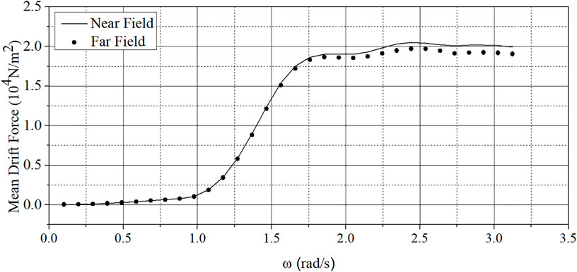
FIGURE 7. Transfer functions of mean drift force.
Motion Responses
To investigate the motion responses of FOWT under two types of mooring system, the time-domain coupled analysis was carried out. The environmental conditions are given in Table 3 (Jonkman and Musial, 2010). The wind and wave incident is along the positive direction of X-axis. The surge, heave, and pitch were the most important DOFs to the mooring system design of FOWT. Therefore, the motion responses of these three DOFs and corresponding power spectral density (PSD) are calculated and presented in Figure 8 and Figure 9. The total duration of numerical simulation was 10,000 s; for the sake of analysis, only 1,000 s of the motion responses are shown in figures.
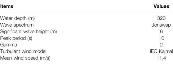
TABLE 3. Environment conditions
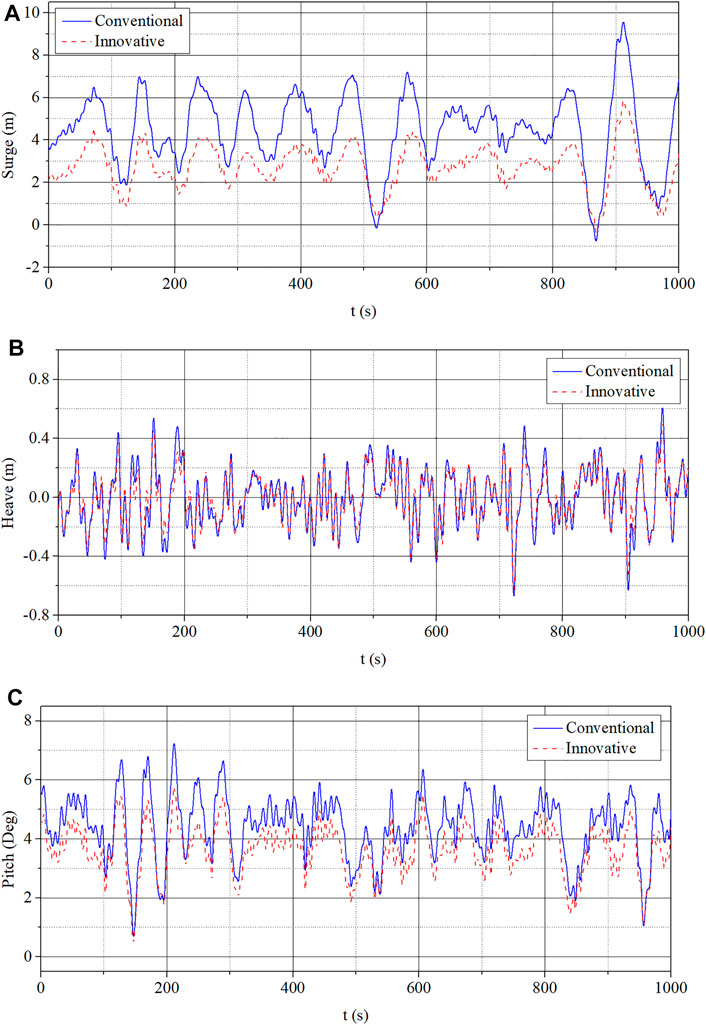
FIGURE 8. Motion responses. (A) Surge. (B) Heave. (C) Pitch.
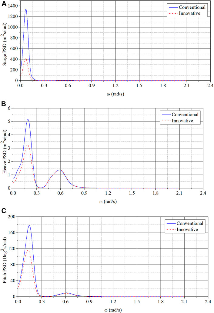
FIGURE 9. PSD of motion responses. (A) Surge. (B) Heave. (C) Pitch.
According to Figure 8, the motion responses of innovative type in surge and pitch DOFs were significantly reduced, compared with the conventional type. The heave motion of innovative type was also reduced. It could be confirmed that the innovative mooring system could effectively reduce the motion responses of the FOWT, especially in the surge and pitch DOFs. Moreover, according to Figure 5 in Section Mooring System, the horizontal static restoring stiffnesses of two mooring systems were basically equal with 0° global pitch angle. Therefore, it could be inferred that the global pitch motions could improve the horizontal motion inhibiting ability of innovative mooring system. Also, it was elaborately explained in the Section Restoring Forces and Moments
According to Figure 9, it was obvious that the motion responses of the FOWT were dominated by the low-frequency component induced by the difference frequency wave forces. The PSD of motion responses under the effects of innovative mooring system were reduced significantly in these three DOFs, especially the low-frequency component, compared with the conventional type. It also proved the better motion inhibiting performance of the innovative mooring system. In addition, it was noticeable that the frequencies corresponding to the peak values of PSD were basically equal between the innovative and conventional types. It indicated that the innovative mooring system would not change the natural frequencies to cause new problems while reducing the motion responses of FOWT.
Furthermore, to quantify the comparison of motion responses, the results were processed statistically, as shown in Table 4. The mean, maximum values, and standard deviations of motion responses under the effects of innovative mooring system were all reduced significantly. Especially in the surge DOF, the mean and maximum values of motion were respectively reduced 37.97% and 38.57%, and in the pitch DOF, the mean and maximum values of motion were respectively reduced 17.87% and 20.64%, compared with the conventional type. It could be confirmed that the innovative mooring system would improve the motion performance of FOWT.
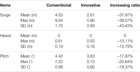
TABLE 4. Motion statistics
Structural Loads
To verify the influences of innovative mooring system on the structural loads of FOWT, the bending moment and shearing force at the tower base are calculated and presented in Figure 10. The corresponding PSD are also given in Figure 11.
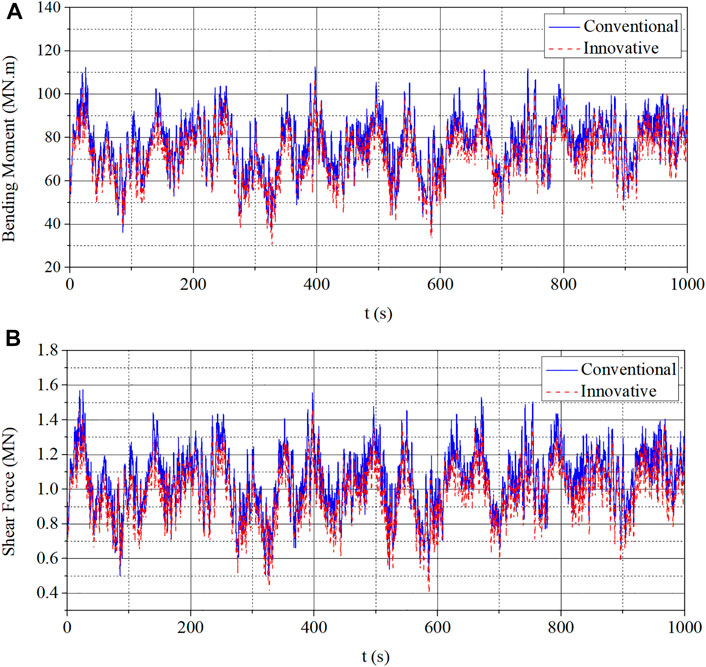
FIGURE 10. Structural loads at tower base. (A) Bending moment. (B) Shearing force.
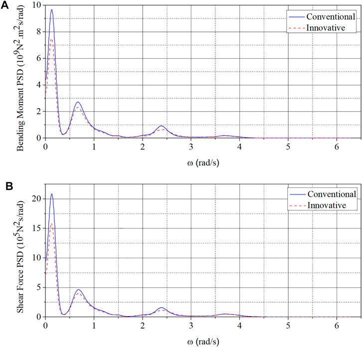
FIGURE 11. PSD of structural loads at tower base. (A) Bending moment. (B) Shearing force.
The bending moment and shearing force at tower base were the most essential structural load components, which were easy to cause problems of structural strength. According to Figures 10 and 11, compared with the conventional type, the bending moment and shearing force at tower base were reduced under the effects of innovative mooring system, especially the low-frequency component, which was consistent with the motion responses. Furthermore, the statistics of structural loads are also given in Table 5 to quantify the comparison. According to the statistics, for the innovative type, the mean values of bending moment and shearing force were respectively reduced 6.45% and 7.81%, compared with the conventional type. The maximum values were respectively reduced 6.14% and 8.18%. In addition, for the innovative type, the standard deviations of these two structural loads were also reduced and it was beneficial to the reduction of fatigue damage.
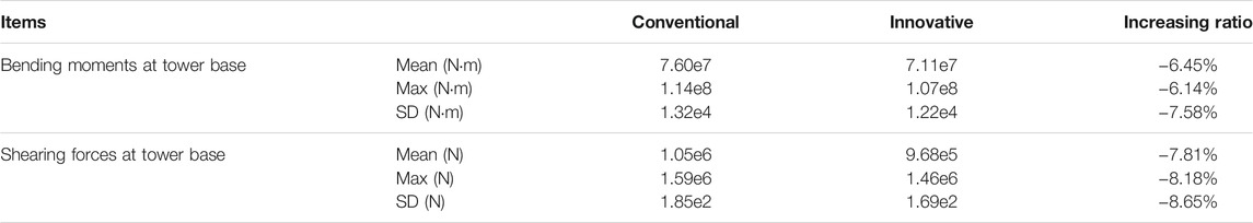
TABLE 5. Structural loads statistics
Restoring Forces and Moments
As verified earlier, the innovative mooring system had significant improvement on motion inhibiting performance in surge and pitch DOFs, compared with the conventional type. To better analyze and compare the performances of these two mooring systems, the restoring force and moment in surge and pitch DOFs are calculated and given in Figure 12. The corresponding statistics are also given in Table 6. It should be noted that the negative signs in figures referred to the direction of force and moment in the reference coordinate system.
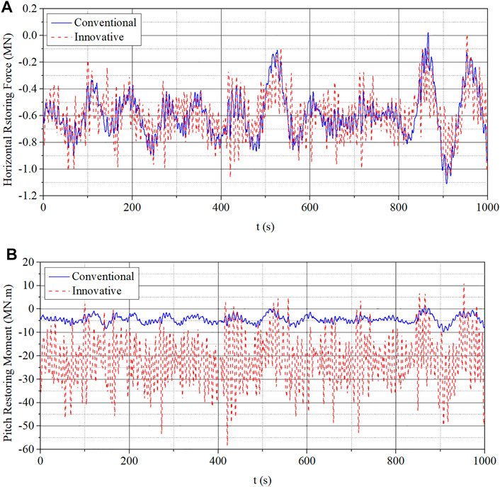
FIGURE 12. Restoring force and moment. (A) Horizontal restoring force. (B) Pitch restoring moment.

TABLE 6. Restoring force and moment statistics (absolute values)
According to the figures, it was noticeable that the restoring moment of innovative type in pitch DOF was nearly a magnitude greater than the conventional type, which was consistent with the calculation of static restoring stiffness. The statistics showed that the mean and maximum values of restoring moment provided by the innovative mooring system were respectively increased 401.13% and 498.15%, compared with the conventional type. However, according to Figure 12 and Table 6, the horizontal restoring forces generated by innovative and conventional mooring systems in surge DOF were basically equal. As presented in Section Motion Responses, the surge motions of innovative type were significantly reduced. It meant that the restoring stiffness in surge DOF was significantly increased, which was not consistent with the horizontal static restoring stiffness in Section Mooring System. As mentioned before, it might have resulted from the coupling effects of surge and pitch motions.
For further analysis, the PSD of horizontal restoring force are presented in Figure 13. It was obvious that the horizontal restoring forces of these two mooring systems were both dominated by the low-frequency component, which was consistent with the natural frequency of surge motion (0.069 rad/s) presented in Figure 9. However, the PSD of innovative type had a peak at the natural frequency of pitch motion (about 0.119 rad/s). It indicated that the horizontal restoring force generated by the innovative mooring system was not only induced by the horizontal motion but also influenced by the pitch motion, which was consistent with the improvement of horizontal restoring stiffness presented in Section Motion Responses. It was caused by the larger vertical distance between two groups of fairleads, which made the innovative mooring system more sensitive to the pitch motion. Moreover, for the innovative mooring type, the wave-frequency component of horizontal restoring force was more significant than the conventional type. This was because the wave-frequency component of pitch motion was more significant than the horizontal motion, as shown in Figure 9, and it was enlarged by the innovative mooring system. Based on the analysis earlier, it could be confirmed that the innovative mooring system could provide greater horizontal restoring stiffness taking advantage of the pitch motion.
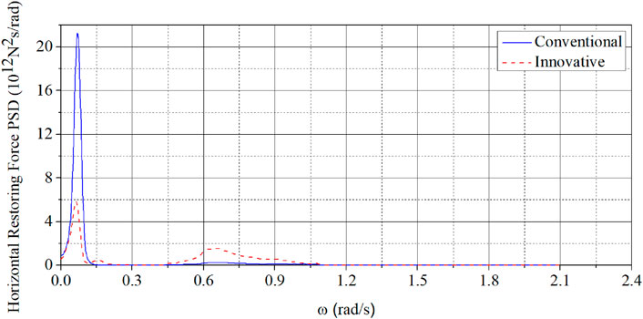
FIGURE 13. PSD of horizontal restoring force.
Conclusion
In this article, an innovative type of mooring system was proposed to reduce the horizontal and pitch motions of FOWT, by dividing the fairleads into two groups at different depths. A conventional mooring system was employed for comparison and the dynamic responses of FOWT with these two mooring systems were calculated and analyzed. Several meaningful conclusions could be drawn as follows:
(1) Compared with the conventional mooring system, the innovative mooring system could generate greater restoring stiffnesses in horizontal and pitch DOFs to significantly reduce the motion responses of FOWT. The maximum values of horizontal and pitch motions could be reduced by 38.57% and 20.64%, respectively.
(2) Compared with the conventional mooring system, the innovative mooring system could reduce the bending moment and shearing force at tower base. The maximum values of bending moment and shearing force could be reduced by 6.14% and 8.18%, respectively.
(3) For the innovative mooring system, the horizontal restoring force is influenced by both horizontal and pitch motions. The pitch motion could improve the horizontal restoring stiffness of innovative mooring system.
In summary, the innovative mooring system proposed in this article could effectively reduce the horizontal and pitch motions simultaneously. Moreover, the bending moment and shearing force at tower base were also reduced significantly.
Data Availability Statement
The raw data supporting the conclusion of this article will be made available by the authors, without undue reservation.
Author Contributions
YM: conceptualization, methodology, software, and writing—original draft. CC: funding acquisition and supervision. TF: conceptualization, methodology, supervision, validation and writing—review and editing. HL: data curation.
Funding
This paper was financially supported by National Natural Science Foundation of China (Grant Nos. 52071145, 51979111, and 52001126), the Guangdong province science and technology project (2021A0505030006), Key-Area Research and Development Program of Guangdong Province (Grant No. 2020B1111010001), The Funds for Marine Economic Development of Guangdong, China (Grant Nos. GDNRC (2021) 39, GDME-2018B003), and The Fundamental Research Funds for the Central Universities (Grant No. 2020ZYGXZR011).
Conflict of Interest
The authors declare that the research was conducted in the absence of any commercial or financial relationships that could be construed as a potential conflict of interest.
Publisher’s Note
All claims expressed in this article are solely those of the authors and do not necessarily represent those of their affiliated organizations, or those of the publisher, the editors, and the reviewers. Any product that may be evaluated in this article, or claim that may be made by its manufacturer, is not guaranteed or endorsed by the publisher.
References
Bae, Y. H., Kim, M. H., and Kim, H. C. (2017). Performance Changes of a Floating Offshore Wind Turbine with Broken Mooring Line. Renew. Energ. 101, 364–375. doi:10.1016/j.renene.2016.08.044
Cummins, W. E. (1962). The Impulse Response Function and Ship motions[R]. Washington DC: David Taylor Model Basin.
Fan, T., Qiao, D., and Ou, J. (2014). Innovative Approach to Design Truncated Mooring System Based on Static and Damping Equivalent. Ships and Offshore Structures 9 (6), 557–568. doi:10.1080/17445302.2013.867631
Guo, H., Lu, X., and Qiu, T. (2012). “Research on Pitch Control of Floating Offshore Wind Turbines[C],” in 2012 9th International Conference on Fuzzy Systems and Knowledge Discovery (IEEE), 2966–2970.
Iino, M., Chujo, T., Iida, M., and Arakawa, C. (2012). Effect of Forced Excitation on Wind Turbine with Dynamic Analysis in Deep Offshore Wind in Addition to Japanese Status of Offshore Projects. Energ. Proced. 24, 11–17. doi:10.1016/j.egypro.2012.06.081
Jonkman, J., Butterfield, S., Musial, W., and Scott, G. (2009). Definition of a 5-MW Reference Wind Turbine for Offshore System development (No. NREL/TP-500-38060). Golden, CO: National Renewable Energy Lab (NREL).
Jonkman, J. (2010). Definition of the Floating System for Phase IV of OC3[R]. Golden, CO, United States: National Renewable Energy Lab.
Jonkman, J. M., and Buhl, M. L. (2005). FAST User’s guide[J]. Golden, CO: National Renewable Energy Laboratory, 365–366.
Jonkman, J., and Musial, W. (2010). Offshore Code Comparison Collaboration (OC3) for IEA Wind Task 23 Offshore Wind Technology and deployment[R]. Golden, CO, United States: National Renewable Energy Lab.
Karimian Aliabadi, S., and Rasekh, S. (2020). Effect of Platform Disturbance on the Performance of Offshore Wind Turbine under Pitch Control. Wind Energy 23 (5), 1210–1230. doi:10.1002/we.2482
Lackner, M. A. (2009). Controlling Platform Motions and Reducing Blade Loads for Floating Wind Turbines. Wind Eng. 33 (6), 541–553. doi:10.1260/0309-524x.33.6.541
Larsen, T. J., and Hanson, T. D. (2007). A Method to Avoid Negative Damped Low Frequent tower Vibrations for a Floating, Pitch Controlled Wind Turbine. J. Phys. Conf. Ser. 75 (1), 012073. doi:10.1088/1742-6596/75/1/012073
Lee, J., and Zhao, F. (2020). Global Wind Report 2019[J]. Brussels, Belgium: Global Wind Energy Council.
Li, Y., Zhu, Q., Liu, L., and Tang, Y. (2018). Transient Response of a SPAR-type Floating Offshore Wind Turbine with Fractured Mooring Lines. Renew. Energ. 122, 576–588. doi:10.1016/j.renene.2018.01.067
Ma, Y., Chen, C., Yan, X., Shen, Y., and Fan, T. (2019). “Analysis on Hydrodynamic Responses of a Spar Offshore Wind Turbine With an Innovative Type of Mooring System,” in International Conference on Offshore Mechanics and Arctic Engineering (American Society of Mechanical Engineers) 58899, V010T09A080.
Ma, Y., Chen, C., Fan, T., Yan, X., and Lu, H. (2021). Research on Motion Inhibition Method Using an Innovative Type of Mooring System for Spar Floating Offshore Wind Turbine. Ocean Eng. 223, 108644. doi:10.1016/j.oceaneng.2021.108644
Shen, X., Hu, P., Chen, J., Zhu, X., and Du, Z. (2018). The Unsteady Aerodynamics of Floating Wind Turbine under Platform Pitch Motion. Proc. Inst. Mech. Eng. A: J. Power Energ. 232 (8), 1019–1036. doi:10.1177/0957650918766606
Taninoki, R., Abe, K., Sukegawa, T., Azuma, D., and Nishikawa, M. (2017). Dynamic Cable System for Floating Offshore Wind Power Generation. SEI Tech. Rev. 84 (53-58), 146.
Thies, P. R., Johanning, L., and Dobral, C. (2017). “Parametric Sensitivity Study of Submarine Power cable Design for marine Renewable Energy Applications[C],” in International Conference on Offshore Mechanics and Arctic Engineering. American Society of Mechanical Engineers, 57663:V03BT02A010.
Xiao, S., and Yang, D. (2019). Large-Eddy Simulation-Based Study of Effect of Swell-Induced Pitch Motion on Wake-Flow Statistics and Power Extraction of Offshore Wind Turbines. Energies 12 (7), 1246. doi:10.3390/en12071246
Keywords: floating offshore wind turbine, mooring system, motion response, structural load, restoring stiffness
Citation: Ma Y, Chen C, Fan T and Lu H (2022) Research on the Dynamic Behaviors of a Spar Floating Offshore Wind Turbine With an Innovative Type of Mooring System. Front. Energy Res. 10:853448. doi: 10.3389/fenrg.2022.853448
Received: 12 January 2022; Accepted: 10 February 2022;
Published: 14 March 2022.
Edited by:
Madjid Karimirad, Queen’s University Belfast, United KingdomReviewed by:
Amir Honaryar, Queen’s University Belfast, United KingdomZhiqiang Hu, Newcastle University, United Kingdom
Gautam Baruah, Queen’s University Belfast, United Kingdom
Copyright © 2022 Ma, Chen, Fan and Lu. This is an open-access article distributed under the terms of the Creative Commons Attribution License (CC BY). The use, distribution or reproduction in other forums is permitted, provided the original author(s) and the copyright owner(s) are credited and that the original publication in this journal is cited, in accordance with accepted academic practice. No use, distribution or reproduction is permitted which does not comply with these terms.
*Correspondence: Tianhui Fan, ZmFudGhAc2N1dC5lZHUuY24=