 Rui He
 Jian Gao
 Aixi Yang2
- 1College of Electrical Engineering, Zhejiang University, Hangzhou, China
- 2Polytechnic Institute, Zhejiang University, Hangzhou, China
Modular design helps to improve the reliability and power density of power electronic systems, so cascading of power electronics modules is an effective method to improve the overall stability of the system. The application of the wireless power transfer (WPT) system to electric buses faces the challenge of higher power requirement; modularization provides a solution to the design of the wireless charging system for electric buses. A modular wireless charging system for electric buses is proposed in this study; the system consists of five identical 6.6 kW wireless charging modules distributed relatively disperse on the chassis. Through the design of coil layout, different modules on the receiver side can be decoupled from each other, which facilitate independent control. Each module utilizes the bipolar-solenoid coupling structure, which proves to have a high misalignment tolerance. In order to reduce the electromagnetic radiation for passengers on the electric bus, shielding is added on the receiver side. Five independent modules work collaboratively to compose a 30 kW wireless charging system for electric buses. The DC-DC efficiency is 87.44% in an aligned position at 200 mm transmission distance. With closed-loop control, the proposed system has high misalignment tolerance in the horizontal X-Y plane. Compared with the open loop control scheme, the average efficiency of the proposed system increases by 22.1% within 300 mm misalignment.
Introduction
Wireless power transfer enables energy transmission from the power source to the load without wires, featuring absolute electrical isolation between the load and the power supply, increased safety, and reliability (Raabe et al., 2007; Hasanzadeh and Vaez-Zadeh, 2015; Hui, 2016). Recently, wireless charging for electric vehicles is becoming a research hotspot in academia (Hasanzadeh and Vaez-Zadeh, 2013a; Lee et al., 2013; Shin, 2014; Choi et al., 2015; Li and Mi, 2015). For electric vehicles and other high power facilitates, loss reduction and efficiency improvement are particularly important. On the other hand, heat dissipation must be taken into consideration; otherwise, power electronic devices and capacitors can be damaged due to overheating (Hasanzadeh et al., 2012; Li et al., 2015; Zhang et al., 2018).
With the increasing demand for charging speed, people have started to pay attention to the wireless charging systems with high power and high efficiency (Hasanzadeh and Vaez-Zadeh, 2013b; Bosshard et al., 2016; Galigekere et al., 2018; Pries et al., 2020). The increase in power will inevitably lead to an increase in the volume of the entire power electronic device, while the space of the car chassis is always limited (He et al., 2019). The modular design of the wireless charging system is a promising method to increase the charging power in an orderly way (Lian et al., 2016). As the WPT system is essentially a high-frequency switching power system, the capacity of the switching power system can be expanded by paralleling sub-modules (Chen and Wang, 2014). This parallel architecture allows for even power distribution among the sub-modules, which helps to reduce the power capacity of each sub-module, and increase the reliability and stability of the system (Bottion and Barbi, 2015). On the other hand, although the sub-modules are connected to each other, each module can be controlled independently (Zhiyu Cao et al., 2010). Compared with the traditional method of purely increasing the capacity of a single power module, the modular design proves to be an effective way to reduce the switch stress and to enhance the robustness of the system.
One problem that incurred by paralleling sub-modules is the unequal current share of different sub-modules as the parameters of various electrical components can hardly be completely consistent (Liu et al., 2014; Wu et al., 2014). This problem becomes more severe if the sub-module has a negative temperature coefficient. As a larger current leads to lower resistance, without additional current-sharing strategies, the sub-system will finally become overload (Tiwari et al., 2015; Hu et al., 2016; Scheuermann, 2016). Typical current-sharing control strategies include the following: the output impedance method, master-slave setting method, average current automatic sharing method, thermal stress automatic current-sharing method, and maximum current automatic current-sharing method (Guerrero et al., 2017; Sadabadi, 2021). In terms of control signals, the control strategies can be further divided into analog and digital modes (Fang et al., 2014). The analog mode is simple and mature, but the bandwidth of the continuous signal is large, and the analog circuit has many discrete components, which makes the analog circuit easily affected by the external interference. The digital mode completes modulation of each single sub-module, which will not adversely affect the operation of other parallel sub-modules. Choosing a reliable and efficient communication method and formulating an appropriate communication protocol are key issues that need to be considered for digital current sharing (Luo and Huang, 2020).
In the wireless charging system, the charging efficiency and charging current depend on the equivalent impedance, which varies during the charging process of a battery. In practical scenarios, misalignment between the transmitter and receiver coils frequently happens in parking, which incurs the alteration of coupling coefficient and results in variation in the system output. A DC-DC converter can be added on the secondary side after the rectifier, in order to maintain the constant current output with load variations (Mcdonough, 2015; Li et al., 2017).
Charging efficiency is always the prior consideration for electric vehicles (Villa et al., 2012). Traditional wireless charging systems always employ a single coil connected with a single power source. However, when the primary and secondary coils are in misalignment, the mutual inductance will rapidly decrease, and the efficiency of the system will drop significantly. Therefore, the inductive coupled transformer and circuit topology needs to be optimized to improve the system efficiency in the occurrence of misalignment (Petersen and Fuchs, 2014; Cao et al., 2018; Tang et al., 2018). Considering the practical situation, misalignment of the coupled transformer in the driving direction of the car can be easily adjusted, but the adjustment of the transverse misalignment can hardly be compensated as the car cannot move directly in the lateral direction. Therefore, the reduction in efficiency caused by the transverse misalignment of the coupled transformer is inevitable. The design of the new coupling structure can effectively alleviate the problem of efficiency reduction caused by misalignment, e.g., utilizing dual-coil on the primary side in the WPT system (Kim et al., 2016).
In order to solve the aforementioned problems, this study proposes a modular wireless charging system for electric buses; the system consists of five identical 6.6 kW wireless charging modules distributed relatively disperse on the chassis. Each module utilizes the bipolar-solenoid structure of the inductively coupled transformer. For each module, two decoupled transmitter coils are applied on the transmitter side. Parameters of the coupling structure are optimized accordingly. In the occurrence of a misalignment, the inverter output voltage of the dual-power supply on the primary side is adjusted by phase-shifting and voltage regulation, so the output power of each primary circuit is adjusted accordingly, and the overall sub-module system efficiency is improved. Each module communicates with each other through the RS485 bus. The WPT module in the center is the master module, and the other WPT modules at the four corners are the slave modules. The slave module receives the command issued by the master module and regulates the primary and secondary controller to make the five modules work in the current-sharing mode in parallel.
System Structure and Theoretical Analysis
System Structure
A conceptual model of modular wireless charging is shown in Figures 1. The system structure of the proposed WPT system is shown in Figures 2; wireless charging system consists of five identical 6.6 kW wireless charging sub-modules, which are distributed on the chassis. Through the design of the coil layout, the different modules of the transmitter can be decoupled from each other, which is convenient for independent control. Each module adopts a bipolar-solenoid coupling structure, and DC-DC converters are added on the secondary side after the rectifier bridge, the five independent modules output in parallel to form a 30-kW electric bus wireless charging power electronic hardware system. Through reasonable design of the distance and angle of adjacent coils, decoupling can be realized between receiving coils and between transmitting coils on the same side.
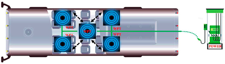
FIGURE 1. Modular high-power wireless charging system for electric vehicles.
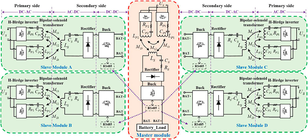
FIGURE 2. Modular WPT system structure.
The system composition of each sub-module is shown in Figure 3. The sub-module WPT is mainly composed of four parts, i.e., the transmitting coil and the receiving coil, the reactive power compensation network of the transmitting coil and the receiving coil, and the power regulating circuit and the load. The DC-AC circuit on the primary side usually uses a voltage-type inverter (VSI), which can greatly reduce the cost of the inductor compared with the current-type inverter (CSI) (Anand et al., 2014). In this system, in order to realize the adjustable power output from the source, the inverter circuit of the dual-power supply on the primary side adopts the phase-shift voltage regulation method to detect and control the effective value of the inverter output square wave. Phase-shift control requires the system to work in the resonant state, and thus, the selection of the compensation network is of vital importance (Sallan et al., 2009). Among the four basic compensation networks, the SS type compensation network has little influence on the resonance state of the primary side (Zhang and Mi, 2016; Fu et al., 2019).
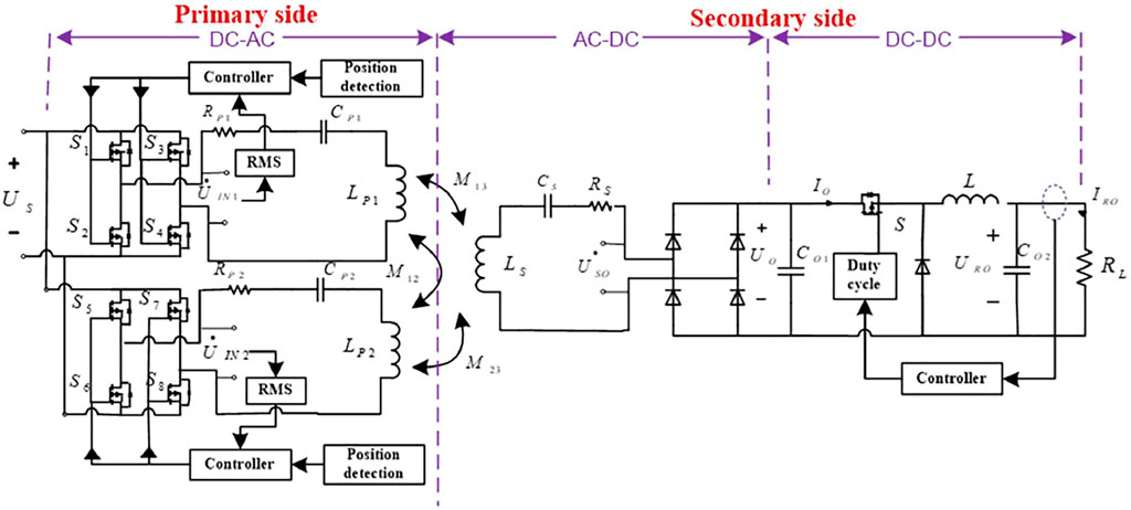
FIGURE 3. Circuit topology of the sub-module in the WPT system.
The change of the secondary side resistive load will not affect the resonance state of the primary side when the load impedance is purely resistive, and the change of mutual inductance caused by the misalignment of the coupling transformer will not affect the primary side system. In order to improve the efficiency of the system and prevent the backflow between the primary side circuits, the primary side of the coupling transformer adopts a bipolar structure coil, in which two coils can be independently decoupled and controlled (Budhia et al., 2010). The secondary side adopts a solenoid structure coil. In order to ensure the stability of the output current, a buck converter is added before the load. On this basis, a simple position detection device is added to the system to determine the misalignment distance of the coupling transformer, and then, the output voltage of the inverter is adjusted in the primary dual-channel power supply of each sub-module to improve the overall efficiency of the modular WPT system.
Theoretical Analysis
The sub-module equivalent circuit model of the modular WPT system is shown in Figure 4. The outputs of the two inverter modules on the primary side can be regarded as independent AC sources UIN1 and UIN2. M12 is the mutual inductance between the primary coils, and M13 and M23 are the mutual inductances between each sub-module primary coil and the secondary coil. USO is the output voltage across the equivalent load on the secondary side, UO is the input voltage of the buck converter, D is the duty cycle of the buck circuit, and L is the freewheeling inductance in the buck converter.
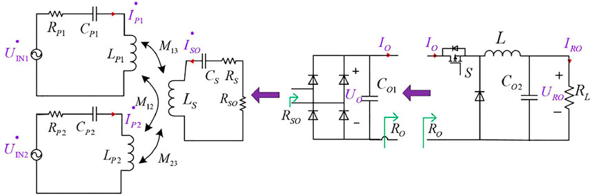
FIGURE 4. Equivalent circuit model of the proposed sub-system.
According to the output characteristics of the buck converter and the conservation law of energy,
The equivalent output resistance is
Through the analysis of the H-bridge rectifier circuit, the following equations can be obtained:
According to Kirchhoff’s voltage law (KVL), the WPT system can be described by the following equations:
The primary side uses bipolar coils that are decoupled from each other, so the mutual inductance between the two primary coils is zero, that is, M12 = M21 When the system is at resonance,
The resonant currents can be deduced by the aforementioned equations:
Analysis of System Output Characteristics
Combined with (1), (3), and (6), the charging current of the load is determined as follows:
The change of the charging current with the mutual inductance M13 and M23 is shown in Figure 5. When the trends of M13 and M23 are complementary, the charging current changes with a small fluctuation. Therefore, the system topology of the sub-module bipolar-solenoid coupler structure has complementary output characteristics, which is more conducive to system output stability than the traditional single coil structure.
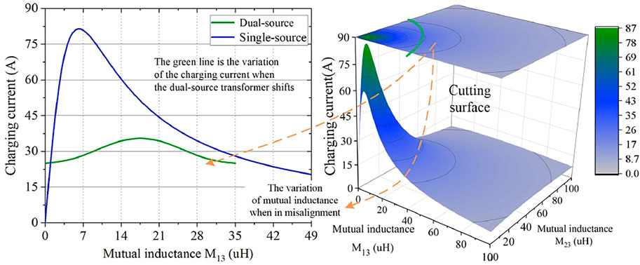
FIGURE 5. Variation of the charging current versus mutual inductance.
The system charging efficiency is
Combined with Eq. 7, the relationship between the efficiency and mutual inductance can be obtained.
As shown in Figure 6, when the transmitter and receiver of the sub-module coupling transformer move in opposite directions, the change trends of M13 and M23 are opposite. The mutual inductance between one primary coil and the secondary coil is large, while the other mutual inductance of the primary coil and the secondary coil is almost zero, and the efficiency of the entire system is about 50%. The reason is that the values of UIN1 and UIN2 are not adjusted according to the scene. When the transmitter and receiver are seriously misaligned, the mutual inductance of a transmitter coil and a receiver coil is very small, and the circuit connected to it is almost short-circuited, but the output power of the receiving side remains unchanged, so the overall efficiency of the system is only half of the rated state.

FIGURE 6. Variation of the efficiency versus mutual inductance.
According to the simulation of the characteristics of the coupled transformer, the mutual inductance M13 = 40uH and M23 = 1.5uH, when the transverse misalignment is 250 mm under extreme conditions, is selected for theoretical analysis.
As shown in Figure 7, when the output voltage UIN2 is greater than 100 V, the system efficiency is less than 60%. When UIN1 is greater than 280 V and UIN2 is less than 30 V, the system efficiency exceeds 70%. Therefore, when the coupling transformer is in misalignment, the primary coil with the smaller mutual inductance is selected, and the inverter output is reduced in order to reduce the primary loop current, thereby reducing the output power of the power supply on that side and improving the overall efficiency of the system.
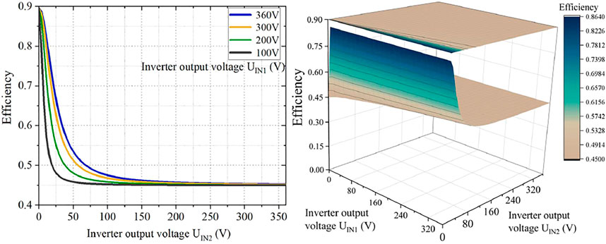
FIGURE 7. Variation of the efficiency versus inverter output voltage.
Design and Optimization of the Loosely Coupled Transformer
Structure of the Loosely Coupled Transformer
The coupled transformer of the modular wireless charging system is composed of five identical sub-modules, as shown in Figure 8. They are in different positions on the same horizontal plane in space. Each sub-module adopts a bipolar-solenoid structure, and the primary transmitting side uses a mutually decoupled independent bipolar coil. The gray ferrite core acts as a magnetic conductor. The secondary side adopts solenoid coils wound around the ferrite cores on both sides and adopts the same strip-shaped cores arranged in the same direction as the primary side.
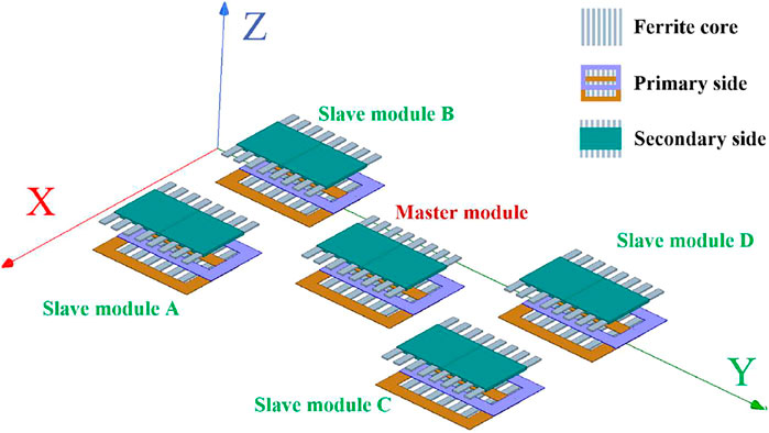
FIGURE 8. Proposed transformer structure of the modular WPT system.
As shown in Figure 9, the primary side of each sub-module adopts a bipolar structure coil. Concerning the design of two independent coils on the primary side, if there is mutual inductance between them, the change of current will affect the loop current of the primary-side double coil, which will change the AC measurement waveform, thereby reducing the system stability and transmission efficiency. When a current is passed into Winding1, the generated magnetic field can be divided into two parts: one part Φ1 penetrates into Winding2, and the other part Φ2 goes out of Winding2. By adjusting the size of the overlapping area between the two windings, the flux-out Φ2 and the flux-in Φ1 can be equal in size and opposite in direction. At this point, the magnetic field generated by Winding1 will not induce the induced current on Winding2, so the two coils are decoupled from each other. The decoupling design is shown in Figure 9; the primary side of each sub-module adopts a bipolar structure coil. When the positions of the two coils overlap, there is a position so that the inductive coupling coefficient between the two primary coils is close to zero. In this state, the current of coil change will not affect each other, thereby improving the system stability.
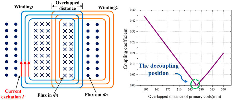
FIGURE 9. Decoupling design of primary two coils.
The specific dimensions of the coupled transformer under the decoupling condition of the primary coils are shown in Figure 10. The design and optimization of the single loosely coupled transformer have been discussed in previous research (He et al., 2020) and are shown in Figure 10. Under this dimension, the coupling coefficient is suitable when the vertical distance between the primary and secondary sides is 200 mm.
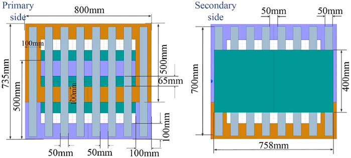
FIGURE 10. Dimension of each coupled transformer.
As shown in Figure 11, the position distribution of five WPT modules on the bus chassis. In order to improve the space utilization, the distance between the five modules should not be too far, but there is a magnetic field between the five modules’ mutual influence.
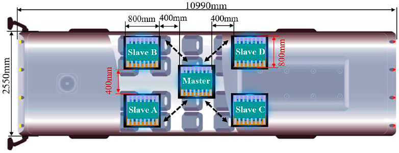
FIGURE 11. Design of coils’ layout under the vehicle.
After the actual simulation test, as shown in Figure 12 , when the WPT system of five modules presents an X-shaped diagonal distribution, the magnetic fields between the modules are decoupled from each other.
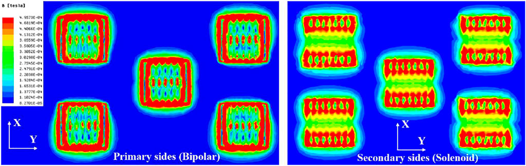
FIGURE 12. Magnetic field distribution of the modular WPT system (X-Y plane).
Misalignment Tolerance of the Proposed Transformer
According to the overall simulation of the coupled transformer of the five WPT systems, it can obtain the variation of the coupling coefficient between the primary coil and the secondary solenoid coil. When the secondary side moves in the X-axis direction and the Y-axis direction, the variation of the coupling coefficient is shown in Figure 13. It can be seen from the simulation results that the coupling coefficients of the two transmitting coils and receiving coils always change in a complementary trend during the entire lateral misalignment process.
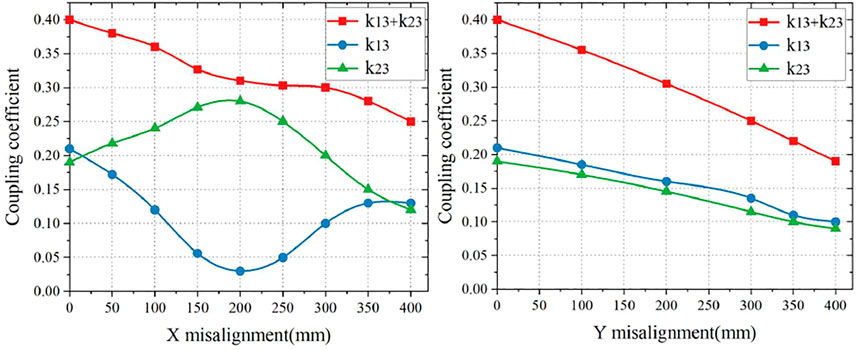
FIGURE 13. Variation of k with misalignment in X and Y directions.
As shown in Figure 14, misalignment in the Z-axis happens when the number of passengers on board changes. Considering the actual situation about urban buses, the rated chassis height is determined to be 200 mm, and the normal range of chassis height is 190–200 mm. When the chassis height is reduced, the mutual inductance between the primary and secondary sides will increase, and the coupling coefficient will increase. According to the simulation result, as shown in Figure 14, the change of coupling coefficient is within 0.015, so the change of coupling coefficient in the Z-axis caused by the decrease in tire pressure is negligible compared to the change in the X-axis and the Y-axis.
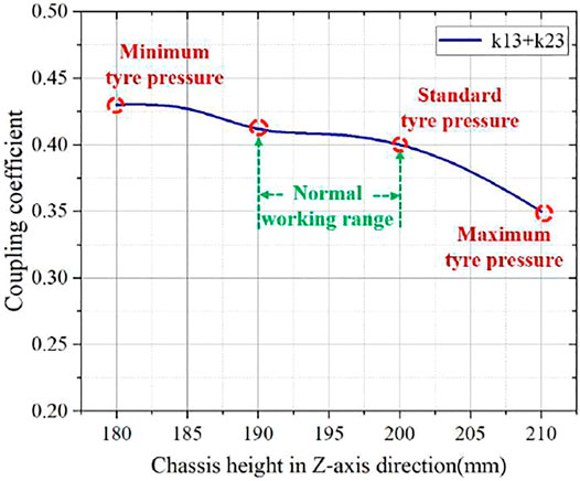
FIGURE 14. Variation of k with misalignment in the Z direction.
Control Strategies for the Modular Wireless Power Transfer System
Control Strategies on the Secondary Side
The design of the secondary side digital current sharing the control system is showning in Figures 15 mentioned to ensure the output stability of the charging system, a buckconverter is added before the load. A PI controller is u sed toadjust the duty cycle of the switch to achieve a constant current output. During start-up, in order to avoid the zero-reflected resistance caused by the open circuit of the secondary side, which will result in huge primary current and overheating of devices, the control unit on the secondary side should be turned on first, and then, the primary controller is turned on afterward. Each module communicates with each other through the RS485 bus. The buck controller of the WPT module in the center is the master module, and the other buck controller of the WPT module at the four corners is the slave module. When the start signal is detected, all the controllers enter the working state at the same time. The sampling circuit monitors the voltage and current of the DC-DC converter. After digital signal processing is performed through DSP, the master module sends the current value through the RS485 bus to the corresponding four slave modules. The slave module A∼D receives the current and voltage reference value given by the master and then controls the PWM signal of the primary and secondary DSP controllers by the PI regulator to make the outputs of five modules work in the current-sharing mode.
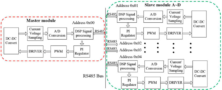
FIGURE 15. Design of the secondary side digital current sharing the control system.
Control Strategies on the Primary Side
The design of the primary side control system in misalignment is showning in Figures 16 mentioned the primary side mainly uses the phase-shift voltage regulation control method to adjust the output power of the system. The principle is to change the effective value of the input square wave voltage by adjusting the phase of the drive signal of the inverter, thereby changing the output AC voltage. The change of the coupling coefficient during the lateral offset can be divided into two position intervals (0, 200 mm) and (200 mm, 400 mm). Since the mutual inductance is proportional to the coupling coefficient, the change trend is the same, and the following formula can be obtained.
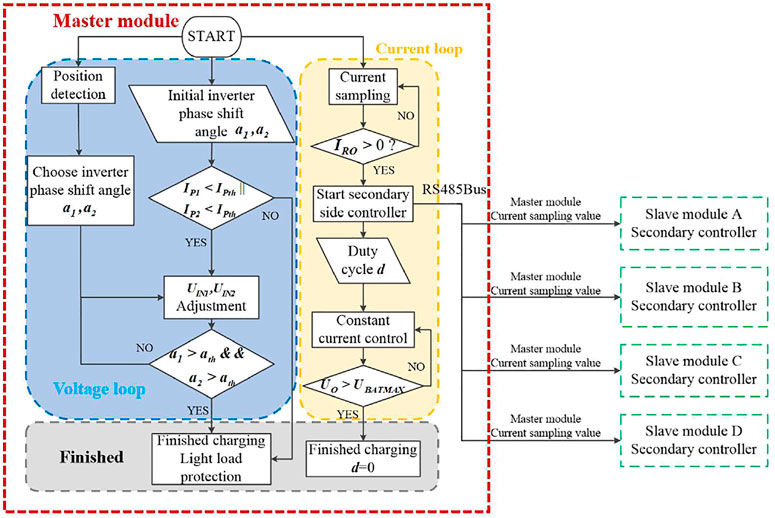
FIGURE 16. Design of the primary side control system in misalignment.
The power supply on the primary side is already started before the bus stops. First, the primary side inverter is set with the initial a1 and a2 angles, and the primary side dual channel currents Ip1 and Ip2 are detected. When the current value exceeds the normal value, it indicates that charging is completed, and then, the light load protection is activated. When the current is within the normal range, the position detection module is started; after collecting the position data, the optimal shift angle is selected corresponding to UIN1 and UIN2 through Formula (11), and the output voltage of the primary inverter is controlled to achieve the maximum efficiency. When it is detected that the secondary-side power loop is turned on and the current IRO>0, the secondary-side control power supply is started to control the output current, and the master module communicates with the slave modules with RS485 in order to realize current sharing in parallel. When the shifting angle a1 and a2 is greater than the threshold or the output voltage UO is greater than the maximum battery terminal voltage UBATMAX, it indicated the end of the battery charge, and the system enters the light load state.
Experimental Results
In order to verify the modular WPT system and the aforementioned analysis, an experimental prototype of the modular WPT system with large misalignment tolerance is set up, as shown in Figure 17. As shown in Figure 17A, the platform of each sub-module is built and verified, and then, the five modules are installed on the vehicle.
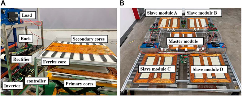
FIGURE 17. Experimental prototype. (A) sub-module WPT; (B) modular WPT system.
The parameters of the modular WPT system are listed in Table 1. The system consists of five identical WPT modules. Each sub-module consists of bipolar-solenoid structure transformers, two high frequency inverters, primary and secondary series resonant network, and rectifiers. Through the configuration of the winding inductance and the capacitor, each sub-circuit works in a series resonance state.
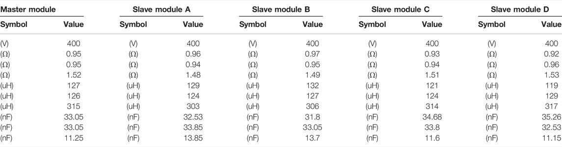
TABLE 1. Parameters of the modular WPT system.
Test waveforms of the modular WPT system in 30 kW are shown in Figure 18: the primary side 1) including the primary current ip, primary voltage up, primary gate voltage ug, and primary protection voltage uprotection (uprotection the voltage signal after the detected resonant current of the switches is rectified, and the signal is scaled down by the op amp circuit. By adding comparators and logic gates in the hardware circuit, we can control the drive signal directly to prevent over-current. Utilizing this method, we do not need to input the sampled value into the DSP for closed-loop processing, and instead, we directly used the hardware for closed-loop control, which results in less response time). The secondary side 2) including the secondary current is and secondary voltage us. It can be seen from Figure 18 that the modular wireless charging system has good stability and efficiency during the operation of 30 kW.
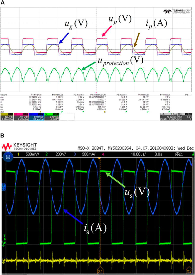
FIGURE 18. Test waveforms of system in 30 kW. (A) Primary side; (B) Secondary side.
The efficiency of the entire modular WPT system power transmission chain is shown in Figure 19. The designed control system can achieve 87.44% efficiency in the aligned position at 200 mm transmission distance. It can be seen that the output power of the five modules is the same. In order to verify the influence of the closed-loop strategy in this study on the overall efficiency of the system, experiments were carried out on the coupling transformers under the condition that misalignment happens in both X and Y axes.
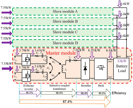
FIGURE 19. System efficiency in the aligned position.
As shown in Figure 20, in the occurrence of X misalignment, the charging efficiency can be greatly improved if the control strategy is adopted. In the occurrence of Y misalignment, the charging efficiency of the closed-loop system is always slightly lower than that of the open-loop system because the primary and secondary side closed-loop control circuit will cause additional losses. In the scenario of providing wireless charging to electric buses, it is easy to adjust the misalignment in the direction of movement of the car (Y-axis), but the adjustment of the lateral misalignment (X-axis) is troublesome. Therefore, if such a modular WPT system is adopted, it will maintain high power output and system efficiency, meanwhile, providing stable output in the present misalignment.
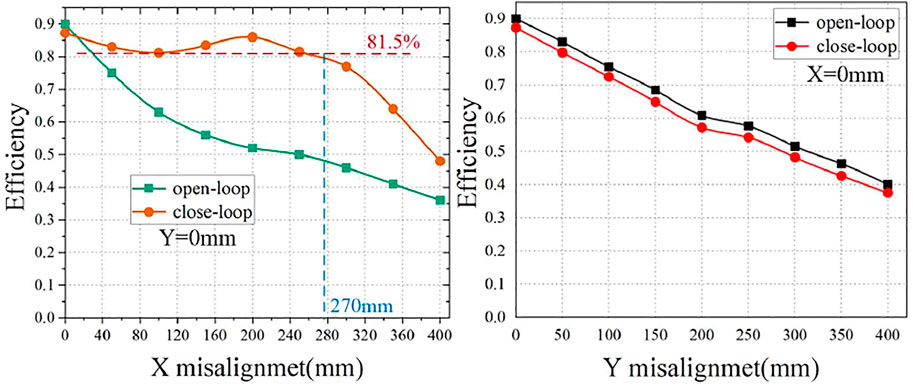
FIGURE 20. Design of the modular WPT system.
Conclusion
This study proposes a modular WPT system which is able to maintain high power and high efficiency in misalignment. The system consists of five identical 6.6 kW wireless charging modules distributed relatively disperse on the chassis. First, the theoretical analysis is carried out for the circuit topology of the sub-module, and the output characteristics of the coupled transformer in misalignment are analyzed. Considering the features of the topology, primary and secondary control strategies are proposed which can realize output current sharing in parallel and effectively improve the system charging efficiency in transverse misalignment. The coupled transformer of the bipolar-solenoid structure is optimized and simulated. The designed control system can achieve 87.44% efficiency in an aligned position at 200 mm transmission distance. With closed-loop control, the proposed system has high misalignment tolerance in the horizontal X-Y plane. Compared with the open loop control scheme, the average efficiency of the proposed system increases by 22.1% within 300 mm misalignment.
Data Availability Statement
The raw data supporting the conclusions of this article will be made available by the authors, without undue reservation.
Author Contributions
RH: conception and design of the study and system analysis. JG: designing computer programs, implementation of the computer code and supporting algorithms, and testing of existing code components. AY: development or design of methodology and creation of models. JZ: management and coordination responsibility for the research activity planning and execution.
Conflict of Interest
The authors declare that the research was conducted in the absence of any commercial or financial relationships that could be construed as a potential conflict of interest.
Publisher’s Note
All claims expressed in this article are solely those of the authors and do not necessarily represent those of their affiliated organizations, or those of the publisher, the editors, and the reviewers. Any product that may be evaluated in this article, or claim that may be made by its manufacturer, is not guaranteed or endorsed by the publisher.
References
Anand, S., Gundlapalli, S. K., and Fernandes, B. G. (2014). Transformer-Less Grid Feeding Current Source Inverter for Solar Photovoltaic System. IEEE Trans. Ind. Electron. 61 (10), 5334–5344. doi:10.1109/tie.2014.2300038
Bosshard, R., Iruretagoyena, U., and Kolar, J. W. (2016). Comprehensive Evaluation of Rectangular and Double-D Coil Geometry for 50 kW/85 kHz IPT System. IEEE J. Emerg. Sel. Top. Power Electron. 4 (4), 1406–1415. doi:10.1109/jestpe.2016.2600162
Bottion, A. J. B., and Barbi, I. (2015). Input-Series and Output-Series Connected Modular Output Capacitor Full-Bridge PWM DC-DC Converter. IEEE Trans. Ind. Electron. 62 (10), 6213–6221. doi:10.1109/tie.2015.2424204
Budhia, M., Covic, G., and Boys, J. (2010). A New IPT Magnetic Coupler for Electric Vehicle Charging Systems. in” IECON on 36th Annual Conference. IEEE Industrial Electronics SocietyIEEE, Glendale, AZ, November 7–10, 2010, 2487–2492. doi:10.1109/iecon.2010.5675350
Cao, P., Tang, Y., and Fan, Z. (2018). An IPT System with Constant Current and Constant Voltage Output Features for EV Charging. in” IECON44th Annual Conference of the. IEEE Industrial Electronics SocietyIEEE, Washington, DC, October 21–23, 2018, 4775–4780. doi:10.1109/iecon.2018.8591213
Chen, W., and Wang, G. (2014). Decentralized Voltage Sharing Control Strategy for Fully Modular Input-Series Output-Series System with Improved Voltage Regulation [J]. IEEE Trans. Ind. Electro. 62 (5), 2777
Choi, S. Y., Gu, B. W., Jeong, S. Y., and Rim, C. T. (2015). Advances in Wireless Power Transfer Systems for Roadway-Powered Electric Vehicles. IEEE J. Emerg. Sel. Top. Power Electron. 3 (1), 18. doi:10.1109/JESTPE.2014.2343674
Fang, W., Liu, X.-D., Liu, S.-C., and Liu, Y.-F. (2014). A Digital Parallel Current-Mode Control Algorithm for DC-DC Converters. IEEE Trans. Ind. Inf. 10 (4), 2146–2153. Nov. 2014. doi:10.1109/TII.2014.2358455
Fu, M., Tang, Z., and Ma, C. (2019). Analysis and Optimized Design of Compensation Capacitors for a Megahertz WPT System Using Full-Bridge Rectifier. IEEE Trans. Ind. Inf. 15 (1), 95–104. doi:10.1109/TII.2018.2833209
Galigekere, V. P., et al. (2018). “Design and Implementation of an Optimized 100 kW Stationary Wireless Charging System for EV Battery Recharging,” in Proc. IEEE Energy Convers. Congr. Expo. (PortlandUSA: OR), 3587–3592. doi:10.1109/ecce.2018.8557590
Guerrero, E., Linares, J., Guzman, E., Sira, H., Guerrero, G., and Martinez, A. (2017). DC Motor Speed Control through Parallel DC/DC Buck Converters. IEEE Latin Am. Trans. 15 (5), 819–826. doi:10.1109/TLA.2017.7910194
Hasanzadeh, S., and Vaez-Zadeh, S. (2015). A Review of Contactless Electrical Power Transfer: Applications, Challenges and Future Trends. Automatika 56 (3), 367–378. doi:10.7305/automatika.2015.12.727
Hasanzadeh, S., and Vaez-Zadeh, S. (2013a). Design of a Wireless Power Transfer System for High Power Moving Applications. Pier M 28, 258–271. doi:10.2528/pierm12102210
Hasanzadeh, S., and Vaez-Zadeh, S. (2013b). Efficiency Analysis of Contactless Electrical Power Transmission Systems. Energ. Convers. Manag. 65, 487–496. doi:10.1016/j.enconman.2012.07.007
Hasanzadeh, S., Vaez-Zadeh, S., and Isfahani, A. H. (2012). Optimization of a Contactless Power Transfer System for Electric Vehicles. IEEE Trans. Veh. Technol. 61 (8), 3566–3573. doi:10.1109/TVT.2012.2209464
He, N., Chen, M., Wu, J., Zhu, N., and Xu, D. (2019). 20-kW Zero-Voltage-Switching SiC-Mosfet Grid Inverter with 300 kHz Switching Frequency. IEEE Trans. Power Electron. 34 (6), 5175–5190. doi:10.1109/tpel.2018.2866824
He, R., Zhou, J., and Hu, C. (2020). A Dual-Source Inductive Power Transfer System Optimized with Large Misalignment Tolerance. in” IECON 2020 the 46th Annual Conference of the. IEEE Industrial Electronics Society, Singapore, October 18–21, 2020, 3855–3860. doi:10.1109/iecon43393.2020.9255125
Hu, J., Alatise, O., Ortiz Gonzalez, J. A., Bonyadi, R., Alexakis, P., Ran, L., et al. (2016). Robustness and Balancing of Parallel-Connected Power Devices: SiC versus CoolMOS. IEEE Trans. Ind. Electron. 63 (4), 2092–2102. doi:10.1109/tie.2015.2500187
Hui, S. Y. R. Magnetic Resonance for Wireless Power Transfer [A Look Back]. IEEE Power Electron. Mag. 3 (1), 14
Kim, P. S., Tejeda, A., Covic, G. A., and Boys, J. T. (2016). Analysis of Mutually Decoupled Primary Coils for IPT Systems for EV Charging. Milwaukee, WI: IEEE Energy Conversion Congress and Exposition ECCE, 1–6.
Lee, S., Choi, B., and Rim, C. T. (2013). Dynamics Characterization of the Inductive Power Transfer System for Online Electric Vehicles by Laplace Phasor Transform. IEEE Trans. Power Electron. 28 (12), 5902–5909. doi:10.1109/tpel.2013.2254500
Li, H., Li, J., Wang, K., Chen, W., and Yang, X. (2015). A Maximum Efficiency Point Tracking Control Scheme for Wireless Power Transfer Systems Using Magnetic Resonant Couplingficiency point Tracking Control Scheme for Wireless Power Transfer Systems Using Magnetic Resonant Coupling. IEEE Trans. Power Electron. 30 (7), 3998–4008. doi:10.1109/tpel.2014.2349534
Li, S., and Mi, C. C. Wireless Power Transfer for Electric Vehicle Applications. IEEE J. Emerg. Sel. Top. Power Electron. 3 (1), 4
Li, Z., Zhu, C., Jiang, J., Song, K., and Wei, G. (2017). A 3-kW Wireless Power Transfer System for Sightseeing Car Supercapacitor Charge. IEEE Trans. Power Electron. 32 (5), 3301–3316. doi:10.1109/tpel.2016.2584701
Lian, Y., Adam, G., Holliday, D., and Finney, S. (2016). Modular Input‐parallel Output‐series DC/DC Converter Control with Fault Detection and Redundancy. IET Generation, Transm. Distribution 10 (6), 1361–1369. doi:10.1049/iet-gtd.2015.0789
Liu, J., Huang, Z., and Peng, J. (2014). “A Novel Bounded Cooperative Multi-Rate Current-Sharing Control for Parallel Charging System with Directed Communication[C] Decision and Control (CDC),” in IEEE 53rd Annual Conference on (IEEE), Los Angeles, CA, December 15–17, 2014, 5654–5659. doi:10.1109/CDC.2014.7040274
Luo, C., and Huang, S. (2020). Novel Voltage Balancing Control Strategy for Dual-Active-Bridge Input-Series-Output-Parallel DC-DC Converters. IEEE Access 8, 103114–103123. doi:10.1109/ACCESS.2020.2999034
Mcdonough, M. (2015). Integration of Inductively Coupled Power Transfer and Hybrid Energy Storage System: A Multiport Power Electronics Interface for Battery-Powered Electric Vehicles. IEEE Trans. Power Electron. 30 (11), 6423–6433. doi:10.1109/tpel.2015.2422300
Petersen, M., and Fuchs, F. W. (2014). Load Dependent Power Control in Series-Series Compensated Electric Vehicle Inductive Power Transfer Systems. European Conference on Power Electronics and Applications, Lappeenranta, August 26–28, 2014, IEEE, 1 doi:10.1109/EPE.2014.691080
Pries, J., Galigekere, V. P. N., Onar, O. C., and Su, G.-J. (2020). A 50-kW Three-phase Wireless Power Transfer System Using Bipolar Windings and Series Resonant Networks for Rotating Magnetic fields. IEEE Trans. Power Electron. 35 (5), 4500–4517. doi:10.1109/tpel.2019.2942065
Raabe, S., Elliott, G. A. J., and Covic, G. A. (2007). A Quadrature Pickup for Inductive Power Transfer Systems. IEEE Conference on Industrial Electronics & Applications.
Sadabadi, M. S. (2021). A Distributed Control Strategy for Parallel DC-DC Converters. IEEE Control. Syst. Lett. 5 (4), 1231–1236. doi:10.1109/LCSYS.2020.3025411
Sallan, J., Villa, J. L., Llombart, A., and Sanz, J. F. (2009). Optimal Design of ICPT Systems Applied to Electric Vehicle Battery Charge. IEEE Trans. Ind. Electron. 56 (6), 2140–2149. doi:10.1109/tie.2009.2015359
Scheuermann, U. (2016). “Statistical Evaluation of Current Imbalance in Parallel Devices}C}//Pcim Europe,” in International Exhibition & Conference for Power Electronics, Nuremberg, May 10–12, 2016 (VDE), 1–7.
Shin, J. (2014). Design and Implementation of Shaped Magnetic-Resonancebased Wireless Power Transfer System for Roadway-Powered Moving Electric Vehicles. IEEE Trans. Ind. Electron. 61 (3), 1179. doi:10.1109/TIE.2013.2258294
Tang, Y., Zhu, F., and Ma, H. (2018). Efficiency Optimization with a Novel Magnetic-Circuit Model for Inductive Power Transfer in EVs. J. Power Electro. 18 (1), 309
Tiwari, S., Rabiei, A., and Shrestha, P. (2015). Design Considerations and Laboratory Testing of Power Circuits for Parallel Operation of Silicon Carbide MOSFETs[C],” in 2015 17th European Conference on Power Electronics and Applications (EPE'15 ECCE-Europe), Geneva, September 8–10, 2015. IEEE, 1–10. doi:10.1109/EPE.2015.7309165
Villa, J. L., Sallan, J., Sanz Osorio, J. F., and Llombart, A. (2012). High-Misalignment Tolerant Compensation Topology for ICPT Systems. IEEE Trans. Ind. Electron. 59 (2), 945–951. doi:10.1109/tie.2011.2161055
Wu, C., Lu, B., and Ge, Y. (2014). A Novel Parallel Current-Sharing Control Method of Switch Power Supply. Toeej 8, 170–177. doi:10.2174/1874129001408010170
Zhang, C., Lin, D., Tang, N., and Hui, S. Y. R. (2018). A Novel Electric Insulation String Structure with High-Voltage Insulation and Wireless Power Transfer Capabilities. IEEE Trans. Power Electron. 33, 87–96. doi:10.1109/tpel.2017.2706221
Zhang, W., and Mi, C. C. (2016). Compensation Topologies of High-Power Wireless Power Transfer Systems. IEEE Trans. Veh. Technol. 65 (6), 4768–4778. doi:10.1109/TVT.2015.2454292
Keywords: modular, wireless power transfer, inductive coupled transformer, misalignment, efficiency
Citation: He R, Gao J, Yang A and Zhou J (2022) Design and Optimization of a Modular Wireless Charging Scheme for Electric Buses With High Misalignment Tolerance. Front. Energy Res. 10:858737. doi: 10.3389/fenrg.2022.858737
Received: 20 January 2022; Accepted: 25 February 2022;
Published: 10 May 2022.
Edited by:
Zhikang Shuai, Hunan University, ChinaReviewed by:
Saeed Hasanzadeh, Qom University of Technology, IranDavid Frey, Université Grenoble Alpes, France
Copyright © 2022 He, Gao, Yang and Zhou. This is an open-access article distributed under the terms of the Creative Commons Attribution License (CC BY). The use, distribution or reproduction in other forums is permitted, provided the original author(s) and the copyright owner(s) are credited and that the original publication in this journal is cited, in accordance with accepted academic practice. No use, distribution or reproduction is permitted which does not comply with these terms.
*Correspondence: Jing Zhou, amluZ3pob3VAemp1LmVkdS5jbg==