 Xiaojie Liu
 Zhaobin Du1,2*
- 1School of Electric Power Engineering, South China University of Technology, Guangzhou, China
- 2Guangdong Province’ New Energy Power System Intelligent Operation and Control Enterprise Key Laboratory, Guangzhou, China
To cope with the volatility and randomness of wind power, photovoltaic (PV) power, and load demands in the islanded microgrid, and also to ensure the safety and economic operation of the islanded microgrid system. A collaborative Distributed model predictive control (Di-MPC) based voltage optimization control strategy is proposed, which considers the strong coupling characteristic of active and reactive power due to the impedance ratio of islanded microgrid, and the requirements of real-time and robustness in the optimization as well. By coordinating the controllable devices in the source-grid-load side of the islanded microgrid, the proposed strategy aims to make full use of the voltage regulation capability of each controllable device. Firstly, by considering the different operating characteristics of the controllable devices, a multi-time scale distributed voltage optimal control model is established. It divides the optimal control process into long-time scale and short-time scale and optimizes for respective objective functions and control variables in different time scales. Secondly, a collaborative Di-MPC-based voltage optimal control strategy is proposed. With the proposed collaboration mechanism, the power output increments of the distributed generators (DGs) are solved in the short-time scale, and the errors in the long-time scale control are also fixed. Finally, the simulation results show that compared with a traditional optimal control method and a centralized model predictive control (CMPC) method, the proposed voltage optimization control strategy can effectively reduce the voltage deviation and fluctuation at each node while ensuring the economic operation of the islanded microgrid system.
1 Introduction
With the growing demand for clean energy in recent years, microgrids, as a limited integration of multiple renewable power generation technologies, have the characteristic of flexibility, scalability, and ease of establishment. It has helped to decentralize and decarbonize energy (Katiraei et al., 2008; Morstyn et al., 2018) and was widely used in many countries (Jiayi et al., 2008), effectively increasing the utilization of renewable energy. Microgrids are usually operated in two modes: grid-connected mode and islanded mode. Due to the small size of islanded microgrids, their dynamic regulation capability is greatly limited by the uncertainty of DGs, such as wind turbine (WT) and PV stations. Moreover, the lack of reactive power support from the external grid makes them more vulnerable to voltage control problems compare to grid-connected microgrids (Han et al., 2016; Mehmood et al., 2021).
At present, the main DGs in the islanded microgrid are WT and PV. Both sources and the load demands have strong randomness and volatility, which brings great uncertainty to the islanded microgrid system. Due to the prediction error of the day beforehand, the system uncertainty will gradually increase as the prediction time moves forward, which makes it difficult to control the islanded microgrid system optimally. To cope with the growing pressure of optimal control for the islanded microgrid system, many works have been done and reported. In contrast to the traditional single-time scale open-loop optimal control method, model predictive control (MPC), as a model-based finite-time rolling optimal closed-loop control method (Ferrari-Trecate et al., 2004; Kouro et al., 2009; Villalon et al., 2020; Hu et al., 2021), can better resist the impact of system uncertainty and show good robustness, and its application in the study of optimal control of power systems has received wide attention. (Liu And Kong, 2013; Wang et al., 2015). In (Raimondi Cominesi et al., 2018), the authors presented a two-layer algorithm for the optimal energy management in MGs, and combined the high-level off-line economic optimization with the low-level online stochastic MPC. In (Xia et al., 2019), to solve the problem of rapid and frequent voltage fluctuations caused by the high proportion of wind power connected to the grid, the authors introduced the multi-time scale optimal control method based on MPC into the reactive voltage control process, which enabled the system to respond to the predictable changes in advance and track the fluctuation of the grid voltage in time. Authors in (Xu et al., 2015) proposed an MPC-based automatic wind farm voltage control method to coordinate the WT and static var generators (SVG). It solved the problems of the time lag and equipment incoordination brought by the traditional reactive power optimization method based on the current time sections for decision-making. In (Yan et al., 2019), the authors proposed a multi-time scale reactive power voltage control method. To fully exploit the dynamic reactive power voltage regulation capability of renewable energy, a multi-time scale reactive power optimization model based on MPC was established, and the voltage overrun caused by the uncertainty factor was well suppressed. However, because of the strong coupling characteristic of active and reactive power caused by the high impedance ratio of islanded microgrid, it is not comprehensive to implement the optimal voltage control while only standing on the perspective of reactive power control. Such an approach ignores the influence of the active power during the voltage control process and limits the optimization space for optimal voltage control in islanded microgrids.
In addition, unlike the main grids, the spacing between source and load in the microgrids is shorter, which causes a strong coupling between active and reactive power. It makes the node voltage not only being affected by reactive power but also closely related to the active power. Therefore, the unilateral analysis of active or reactive power optimization in microgrids based on the traditional active and reactive decoupling method is inadequate and inaccurate. In (Zhang and Wang, 2016), the authors proposed an MPC-based coordinated optimization method of active and reactive power dispatching for microgrid, considering voltage constraints. Then a real-time rolling optimization was used to optimize the power outputs of microsource and energy storage system (ESS), which achieved the purpose of economic and stable operation of the microgrid and reduced the voltage deviation of nodes within the system. Authors in (Gao et al., 2018) used the branch flow model-based relaxed optimal power flow to optimize the robust coordinated optimization of active and reactive powers, which is described as a mixed-integer second-order cone programming problem. In order to address the uncertainty of renewable energy and load demand, a two-stage robust optimization model was proposed. In (Zhang et al., 2017), the authors proposed an MPC-based active-reactive power coordination control method for distribution networks with distributed photovoltaic stations, which performed separate MPC at different time scales for respective control objectives and control variable, then the established non-convex and non-linear model was solved by using the second-order cone programming in a relaxed manner. However, with the growing number of controllable DGs and devices within the microgrid, centralized method like CMPC approach used in the above-mentioned research will face great challenges. The traditional centralized control method relies on global information, and when the number of controllable devices increases, the pressure on computation and communication will become intense. Moreover, the original model has to be readjusted once there are any devices withdrawn from failure, which makes the method less robust and scalable, and cannot adapt to the requirements of microgrid operation and control in the context of increasing penetration of DGs.
Furthermore, in order to achieve the real-time and robust requirements of voltage optimization control in the microgrids, distributed control method like Di-MPC has been approached for its advantages of high reliability, flexibility, and fast solution, and it also overcomes the shortcomings of the traditional CMPC. In (Zheng et al., 2018), authors combined the Di-MPC method to transform the microgrid energy dispatching problem into several interconnected non-linear and integer planning problems, which simplifies the plug-and-play feature. The proposed method reduces the computation of the problem to a large extent and improves the solution efficiency. Authors in (Guo et al., 2019) combined with the consistency-based distributed information synchronization and estimation to coordinate and optimize the control of the active and reactive power outputs of the wind farm, which ensures that the WT tracks the reference frequency while reducing its fatigue load through active power control, and reduces the deviation of the node voltage through reactive power/voltage control. In (Zhao et al., 2020), the authors proposed a control strategy based on Di-MPC to optimize the economic scheduling of multi-microgrids on island groups. The proposed strategy designed a trading mechanism by using dynamic non-cooperative game theory to regulate trading behavior between microgrids with different owners. Authors in (F. et al., 2021) proposed a distributed model predictive control strategy for the operation of isolated microgrids based on a consensus strategy, which can tackle both the economic dispatch and frequency restoration over the same time scale. It is also robust to load variations and communication issues. Authors in (Fan et al., 2021) presented a distributed discrete-time control scheme for the DC microgrids, and it had achieved the optimal coordination of CGs and RGs, where the generation cost of the CGs is minimized, and the energy utilization of RGs is maximized. In (Yang et al., 2021), the authors proposed a novel distributed model predictive control (DMPC) strategy for a DC microgrid based on voltage observers for multiple energy storage systems (ESs) to achieve a tradeoff between voltage regulation and power-sharing. In order to reduce the impact of communication delay on voltage observers, an improved DMPC consensus algorithm is proposed, which effectively improves the robustness of the system to the delay.
Meanwhile, for multi-energy systems such as microgrids, many works have also been done and reported (Li et al., 2021). The authors in (Liu and Yang, 2022) established a multi-objective optimization model with operating costs and gas emissions as the competing objective functions, simultaneously. To achieve the purpose of optimal energy dispatching with reasonable operating costs and gas emissions, a distributed algorithm with dynamic weights based on initial values was proposed, where participants only need to share information with neighboring controllers to achieve energy management. In (Li et al., 2020), the authors established a double-mode energy management model for the multi-energy system, which modeled the islanded and network-connected modes into a unified and distributed form. Then, a novel distributed dynamic event-triggered Newton-Raphson algorithm is proposed to solve the double-mode energy management problem in a fully distributed fashion, in which the adaptability and flexibility of the multi-energy system can be enhanced. Therefore, distributed control methods are more in line with the needs of the engineering practice for their real-time and robust performance, which can better coordinate the controllable devices within the multi-energy system.
Thus based on the collaborative Di-MPC, this paper proposes a method for optimizing the active-reactive power coordinated voltage control of islanded microgrid by considering multiple controllable devices on the source-grid-load subsystems, which divides the whole optimization control process into long-time scale and short-time scale according to the different action speeds and limits of the controllable devices. In different time scales, different control objectives and control variables are optimized. For long-time scale, based on the WT power, PV power, and load demands day-ahead forecast data, the active and reactive power outputs of each DG, the gear of on-load tap changer (OLTC), and the number of capacitor banks (CB) are optimally solved to minimize the system network losses. For short-time scale, the results of the long-time scale optimization are used as the initial values, and the voltage/reactive power sensitivity model is used as the voltage prediction model, based on the real-time WT power, PV power, and load demand forecast values. By calculating the active and reactive power output increments of the micro gas turbine (MT) and ESSs, as well as the reactive increments of WT and PV stations, it aims to minimize the voltage deviation and fluctuation so that the islanded microgrid system can run in a safe and economical way.
The main contributions and salient features of this paper are as follows:
1. Considering the strong coupling characteristic of active and reactive power that caused by the high impedance ratio of islanded microgrid, also the uncertainty of renewable energy and load. A multi-time scale source-grid-load active-reactive coordinated voltage optimization control strategy is proposed, which expands the optimization space of the traditional active-reactive decoupling method. The proposed strategy also enhances the ability of the islanded microgrid to cope with the uncertainty through the collaborative regulation mechanism of controllable devices in different time scales.
2. Considering the requirements of real-time and robustness of the regulation method in short time scale optimization stage. A source-load collaboration mechanism based on Di-MPC was proposed. In the proposed mechanism, the coordination problem between the agents is reduced to a cooperative game where they have to choose one out of the three strategies, and only two rounds of information interactions are required to reach an agreement. Therefore, it has a good performance of real-time and robustness.
2 Active-Reactive Power Coordinated Optimal Control Strategy Based on Distributed Model Predictive Control
2.1 Collaborative Distributed Model Predictive Control Theory
MPC is a model-based finite-time domain closed-loop optimization control algorithm, which is a process control method with easy modeling, good applicability, and high robustness. Based on this feature, MPC is widely used in the field of optimal control of power systems as a control algorithm with both applicability and robustness, and its basic framework consists of three major parts: predictive model, cost function, and solving algorithm (Villalon et al., 2020; Hu et al., 2021). The first element of the control sequence is applied to the controlled object, and at the next sampling moment, the optimal control problem is reconstructed based on the system state and the new measurement values after the control execution in the previous moment, and the above process is repeated (Rawlings and Mayne, 2009).
Traditional CMPC has a simple structure, and it is easy to implement because only one centralized controller needs to be designed to control the whole interconnected system. However, on the one hand, with the increasing number of distributed devices in the interconnection system, the computation burden of the centralized controller increases significantly, which has a significant impact on performing the real-time online rolling optimization. On the other hand, it lacks robustness since when one of the subsystems fails and withdraws from the interconnection system, the CMPC needs to correct the model in time to avoid wrong control command, which will cause the crash of the system. The correction is very time-consuming and complicated. Considering the shortcomings of CMPC, this paper adopts the collaborative Di-MPC to solve the voltage optimization problem. Di-MPC firstly decomposes the interconnected system into several subsystems with coupling relationships, and each subsystem can obtain the global information of the interconnected system through communication. Compared with CMPC, Di-MPC decouples a large online optimization problem and distributes them to each subsystem for a solution. Each sub-optimization problem is not only independent but also coupled, and each sub-optimization problem can be independently and parallelly solved, thus it greatly reducing the scale and complexity of solving the online optimization problems and improving the solution efficiency while ensuring the control performance (Le et al., 2020).
2.2 Multi-Time Scale Source-Grid-Load Active-Reactive Power Coordination and Optimal Control Strategy Based on Collaborative Distributed Model Predictive Control
In addition, the network-side devices have a slow response time when participating in the voltage regulation, so they should not be operated frequently. On the contrary, each DG in the source side is connected to the islanded microgrid through the inverter, and the fast response characteristics of the inverter itself enable the DGs to operate in a short time during the voltage regulation process. So the proposed collaborative Di-MPC carefully considers the operating characteristics of the above devices and comprehensively utilizes the regulatory potentials in the source-grid-load side. Based on the collaborative Di-MPC, a multi-time scale distributed voltage optimal control model is established in this paper proposes. The long-time scale optimal control model ensures the safety and the economic operation of the system, and the short-time scale optimal control further optimizes the voltage control effect. Thus each DG can ensure the economical and safe operation of the system while making full use to the voltage regulation capability of each controllable device in the source-grid-load side. The schematic diagram of the multi-time scale optimal control is shown in Figure 1.
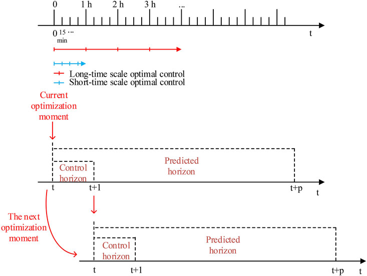
FIGURE 1. Multi-time scale optimal control schematic.
3 Multi-Time Scale Optimal Model of Active-Reactive Power Coordinated Voltage Optimization Control
3.1 Long-Time Scale Optimal Control Model
The long-time scale optimal control model takes the active and reactive power outputs of ESS and MT, the reactive power outputs of WT and PV stations, as well as the gear of the OLTC and the number of the CB as control variables, and the predicted data of wind power, photovoltaic power and load demands as input variables. Then by using 1 h as the optimization time window to optimally solve the above control variables.
3.1.1 Optimization Objective
The optimization objective of the long-time scale optimal control is to ensure the economical operation of the islanded microgrid system and reduce the network losses, so the objective function is designed to minimize the system network losses, described as:
where
3.1.2 Constraints
1) Power flow constraints
The used LinDistflow model (Baran and Wu, 1989; Šulc et al., 2014) can linearize the original non-linear and non-convex power flow constraint, as well as the on-load tap changer constraint, which allows it to solve the original optimal control problem in a more efficient manner without affecting the precision, described as:
where
2) Voltage constraints
where
3) DGs and other devices operating constraints
1) WT operation constraints
where
2) PV stations operation constraints
where
3) MT operation constraints
where
4) ESS operation constraints
where
5) OLTC operation constraints
where
For the branch containing the OLTC, the voltage constraint is modified as
6) CB operation constraints
where
3.2 Short-Time Scale Optimal Control Model
The short-time scale optimal control model takes the active and reactive power output increments of MT and ESS, the reactive power output increments of WT and PV station as the control variables. It also takes the power outputs and actions of each DG and controllable device, and the voltage of each node solved by the long-time scale optimal control as the input variables. Then by using 15 min as the optimization time window in this stage to optimally solve the above control variables.
3.2.1 Optimization Objective
The optimization objective of the short-time scale optimal control aims at further reducing the voltage fluctuations based on the long-time scale optimal control regulation, which are due to the fluctuations of the wind power, photovoltaic power, and load demands. The optimization objective function is described as:
where
3.2.2 Constraints
The constraints in short-time scale contain the operation constraints of DGs and ESS as shown in Eq. 13, Eq. 14, respectively.
where
3.2.3 Voltage Prediction Model Based on Voltage/Power Sensitivity
Islanded microgrids are mainly powered by renewable energy sources such as wind power and photovoltaic power, which are subjected to environmental uncertainties. Combined with the characteristics of the islanded microgrid transmission lines, the voltage of each node will be affected when the output of WT and PV stations fluctuates due to environmental impacts. In order to control the DGs in time to achieve the purpose of voltage regulation, it is necessary to predict the node voltage fluctuations caused by the fluctuation of wind power, photovoltaic power, and load demands. Then reasonably arrange the power outputs of each DG to reduce the voltage deviation and fluctuation. In this paper, from the perspective of active-reactive power coordination control, in order to regulate the system voltage, the active and reactive power outputs of DGs inside the islanded microgrid is regulated under different stages. Based on the conventional AC power flow equation, the non-linear power flow is linearized at the steady-state solution of the power flow, and the following matrix can be obtained (Wang et al., 2005):
where
The inverse of this matrix expression yields:
where
Then the voltage in node j at time t can be expressed as
Equation 18 will be used as the predictive model in the short-time scale optimal control process, which can forecast the node voltage under fluctuating wind power and photovoltaic output as well as load demand.
4 Active-Reactive Power Coordinated Voltage Optimization Control Based on Collaborative Distributed Model Predictive Control
4.1 Problem Description of The Optimal Control Model
The islanded microgrid source-grid-load active-reactive power coordinated voltage optimization control problem studied in this paper contains continuous control variables, which are the power output of DGs and ESS. The problem also contains discrete control variables, which are the gear of OLTC, the switching group of CB, and the charging and discharging states flags of ESS. All the above variables form a multi-variable mixed integer programming problem with multiple constraints. According to the operating characteristic of the devices placed in the source, network, and load side, the problem is divided into long-time scale and short-time scale and solved.
4.2 Collaborative Control Mechanism
4.2.1 Long-Time Scale Optimal Control
The main optimization objectives in the long-time scale optimal control is to minimize the active network losses of the day-ahead islanded microgrid system, ensure the safety and economic operation of the islanded microgrid, and provide the initial reference voltage and the initial values of the active and reactive power outputs of each DG for the intra-day rolling voltage optimization. Among them, ESS is considered as the load-side device in this paper due to its charging and discharging power characteristics. The main control member in the long-time scale optimal control are WT, PV stations, and MT, which are considered as source-side devices. The on-load tap changer and capacitor banks are as considered as network-side devices.
4.2.2 Short-Time Scale Optimal Control
In the short-time scale optimal control, since it is not suitable for network-side devices such as OLTC and CB to operate in a short time period, only the source-side and load-side devices are optimized and controlled. The source-side devices and load-side devices of the islanded microgrid system are regarded as two interconnected subsystems, and corresponding agents under the structure of DI-MPC are set in each subsystem to carry out the coordinated control of active and reactive power. After receiving the optimization results of the long-time optimal control, the first communication between the agents of each subsystem is carried out. The source and load-side agents calculate their own selfish solutions and altruistic solutions through information interaction and then carry out the second communication. Each agent generates a 3 × 3 strategy table according to the obtained conservative solutions, selfish solutions, and altruistic solutions. Since both agents contain the same information of the system at this time, both agents finally choose the same control strategy in the strategy table that makes the global objective function optimal.
To better describe the proposed mechanism, the following definitions are introduced (Maestre et al., 2011):
To discuss the designed inter-agent collaboration mechanism in terms of the game theory. At each time step of the collaborative Di-MPC, both source and load agents can be regarded as participating in a mutual cooperation game, each subsystem agent interacts with each other in two rounds of computation, the source agent sends the selfish solution
The cooperative game can be represented by a 3 × 3 strategy table. Each row of the table represents one of the three possible strategies of the source agent, and each column represents one of the three possible strategies of the load agent, and each cell contains the sum of the respective objective functions of each agent for the specified future input control sequence. That is, at each time step, each agent selects the control sequence combination that minimizes the sum of the objective functions. Because both agents share the same information with each other, in the end, they will choose the same combination of control sequences, and this combination of control sequences is the optimal strategy at the current moment. The 3 × 3 strategy table is shown in Table 1.

TABLE 1. Objective function-based strategy table.
The nine strategies in the table are expanded and as shown in the following equation
The algorithm flowchart of the collaborative Di-MPC-based islanded microgrid source-grid-load active-reactive power coordinated voltage optimization control strategy is shown in Figure 2. T1, T2 are the optimal time cycles of long-time scale optimal control and short-time scale optimal control, respectively.
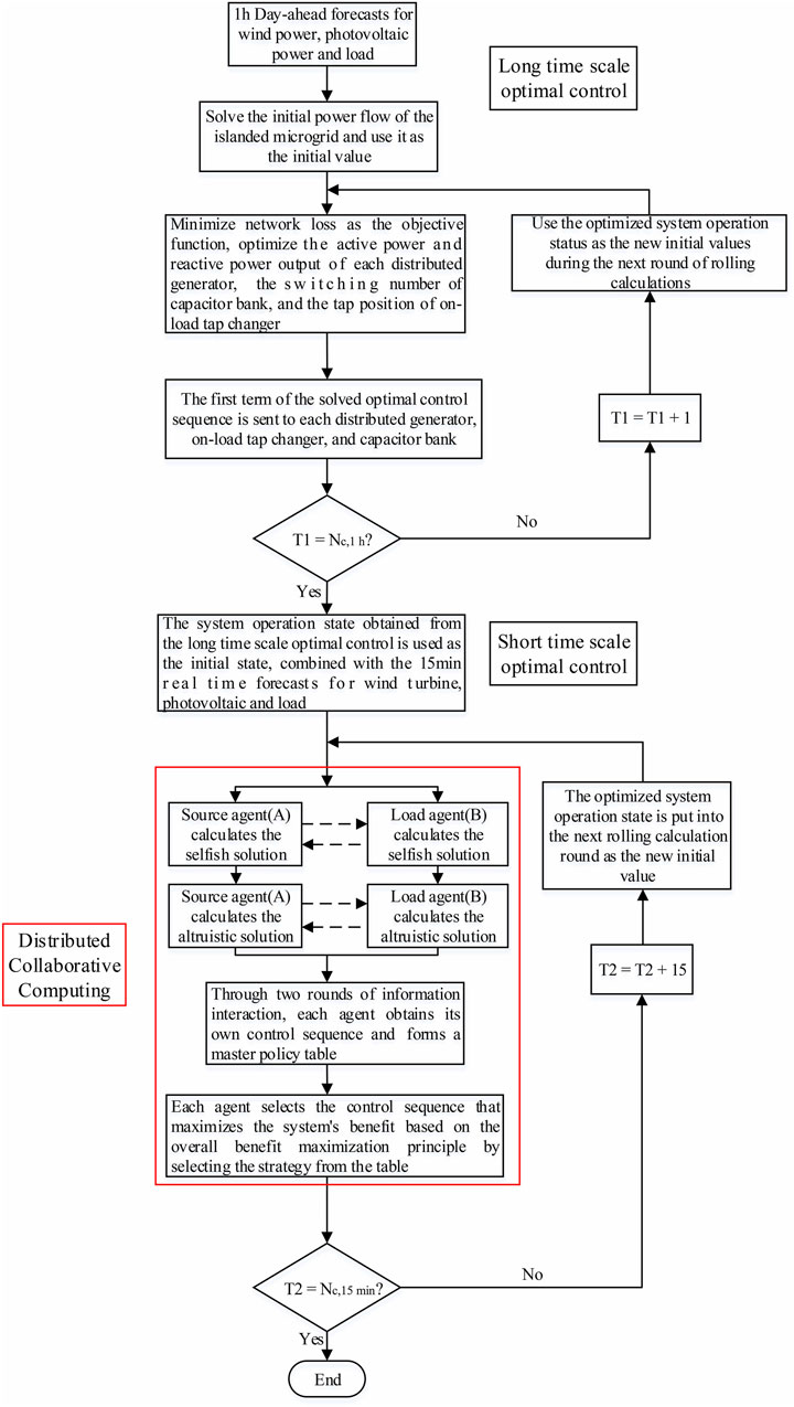
FIGURE 2. Algorithm flowchart of the collaborative Di-MPC for islanded microgrid source-grid-load active-reactive power coordinated voltage optimization control strategy.
5 Case Results and Discussion
5.1 Parameter Setting
In this paper, we adopt the adapted IEEE 33-BUS system, which is used for simulation analysis and as shown in Figure 3. The reference value of the microgrid is set to:
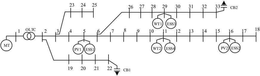
FIGURE 3. Adapted IEEE 33-BUS system.

TABLE 2. Place location of DGs and other devices.
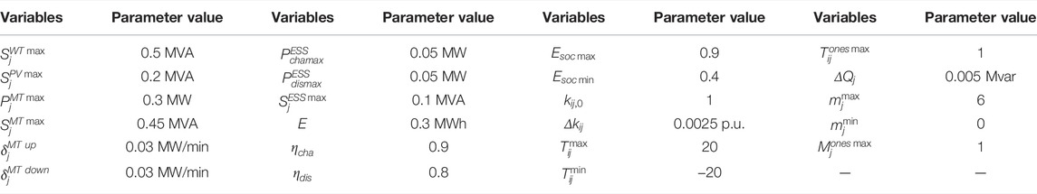
TABLE 3. Simulation parameters.
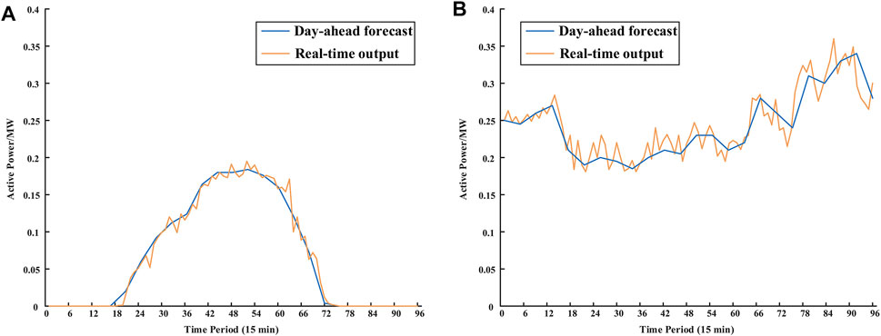
FIGURE 4. (A) Day-ahead forecast and real-time active power outputs of PV stations. (B) Day-ahead forecast and real-time active power outputs of WT.
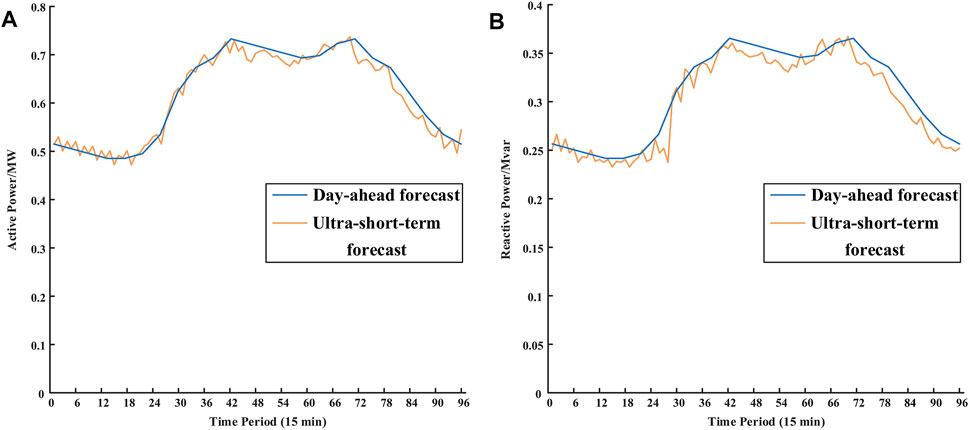
FIGURE 5. (A) Day-ahead and ultra-short-term active load damands forecast. (B) Day-ahead and ultra-short-term reactive demands load forecast.
In order to verify the effectiveness of the proposed strategy, two other active-reactive coordinated voltage optimization strategies are compared to solve the same study case.
Strategy 1: Single-time scale conventional optimal control.
With the objectives of minimizing the active network losses, as well as the total voltage deviation of each node and the minimum voltage fluctuation in adjacent time periods, a traditional optimal control strategy with a single-time scale is used to optimally control all the devices involved in the voltage regulation within the islanded microgrid.
Strategy2: Multi-time scale CMPC.
With the objective of minimizing active network losses, the OLTC and CB switching schedule (24×1 h) and the active and reactive power outputs of DG are uniformly optimized before the day. During the day, the active and reactive power output increments of each DG are optimized on a rolling basis (96 × 15 min) using CMPC with the objective of minimizing the total voltage deviation of each node, as well as the voltage fluctuation in adjacent time periods (Liu et al., 2016). All the control instructions are performed through one centralized controller in this strategy.
Strategy 3: Multi-time scale collaborative Di-MPC.
With the objective of minimizing active network losses, the OLTC and CB switching schedule (24×1 h) and the active and reactive power outputs of DG are uniformly optimized before the day. During the day, the active and reactive power output increments of each DG are optimized on a rolling basis (96 × 15 min) using collaborative Di-MPC with the objective of minimizing the total voltage deviation of each node, as well as the voltage fluctuation in adjacent time periods. The final control instruction is generated and performed after the interaction between the two agents is complete.
5.2 Optimal Control Results Under Normal System State
1) Network losses result analysis
The system network losses result after applying three different optimal control strategies is shown in Figure 6. It can be seen that the network losses change under the multi-time scale optimal control strategy and all have the same trend. When the PV power decreases and the load demands increase in the evening hours, the network losses increase. Then by adjusting the DGs in the system, their output increases, and the network losses decrease. Through the vertical comparison, the proposed strategy can significantly reduce the network losses, and the maximum intra-day reduction is 65.38% compared with the conventional optimal control method, which can ensure the safe and cost-effective operation of the islanded microgrid system.
2) DGs output results analysis
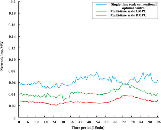
FIGURE 6. System network losses under three different strategies.
The active power outputs of each DG in the islanded microgrid are shown in Figure 7. From the figure, we can see that wind power and PV power undertake the majority of the active load demands, which significantly reduce the phenomenon of wind and light abandonment and improves the effective utilization rate of DGs. The surplus power that occurs is stored by ESS. Figure 8 shows the reactive power outputs of each DG and CB. The results demonstrate that, although the frequency and amplitude fluctuations of each DG are large, the total reactive power outputs still match the trend of reactive load demands. The reactive power regulation limit of each DG depends on its active power outputs and rated capacity. The anti-peak regulation characteristic of WT is conducive to the expansion of its reactive power regulation space during the daytime, so that PV has sufficient reactive power margin when it is not generating at night, and the reactive power compensation is limited by the centralized power outputs during the daytime, forming a complementary trend with wind power.
3) Voltage control results analysis

FIGURE 7. DGs active power output results in the islanded microgrid.
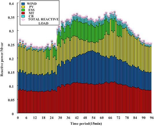
FIGURE 8. DGs reactive power output results in the islanded microgrid.
The voltage control results of nodes 5, 11, and 18 under three optimal strategies are shown in Figure 9.
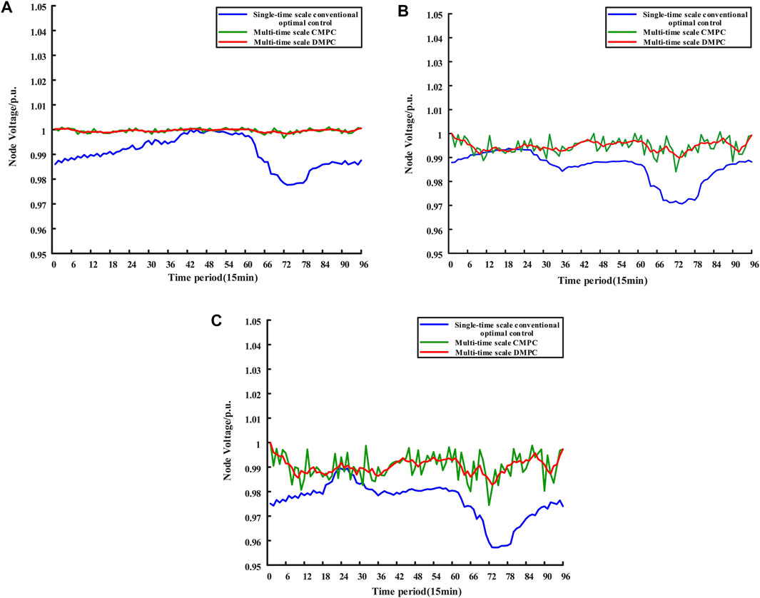
FIGURE 9. (A) Voltage control result of node 5. (B) Voltage control result of node 11. (C) Voltage control result of node 18.
As shown in Figure 9, although the three strategies used in the study case can control the voltage of the three typical nodes within the safe limits, the voltage fluctuations of nodes 5, 11, and 18 are greater under the conventional optimal control method with a single time scale. In contrast, while under the multi-time scale optimization control method, the overall voltage fluctuation trend of node 5 at the beginning of the transmission line is gentle, and the voltage fluctuation increases as the position moves back, but the voltage fluctuation of each node is the smallest with the third strategy compared to other strategies, which demonstrate the best voltage control effect.
5.3 Optimal Control Results Under Faulty System State
In order to reflect the applicability and robustness of the proposed strategy, it is assumed that the PV station originally placed at the No. 16 node is out of operation due to a failure, which is a large system state changing for the island microgrid system with weak adjustment capability. At this time, it is necessary to appropriately optimize and control the controllable devices in the system to deal with the failure and avoid larger problems. The applicability and robustness of the proposed strategy are reflected by comparing the network losses and voltage fluctuation of the key nodes under the three different strategies.
1) Network losses results analysis
As can be seen from Figure 10, compared with the system under normal state, both the amplitude and fluctuation range of the network losses have increased, indicating that the self-regulation ability of the islanded microgrid system will be weakened when facing the generator failure. It is more necessary to reasonably coordinate the controllable devices to make up for the lack of regulation ability. In addition, we can see that among the three optimal control strategies adopted, the strategy proposed in this paper significantly reduces the network losses by 76% at the moment of the maximum network losses in the daily time. Therefore, the proposed strategy can still effectively reduce network losses when dealing with system failures and shows certain applicability and robustness.
2) Voltage control results analysis
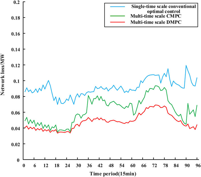
FIGURE 10. System network losses under three different strategies.
From Figure 11A, we can see that compared to the normal system state, due to the connection of PV station and ESS at node-5, although the voltage fluctuation at node-5 has increased, the overall trend remains consistent with the level before the fault. However, node 18 is at the end of the transmission line, which has a large voltage fluctuation. Node 16, which is related to node-18, was in the middle section of the transmission line, and it is connected with a PV station as well as an ESS. When the PV station and the ESS were out of operation, node-18 needs to deal with its own load fluctuations while facing a longer power transmission distance, which will make the voltage regulation of the node more difficult. As can be seen from Figure 11B, the proposed strategy primely solved the voltage fluctuation problem faced by node-18 and reflects a better voltage control effect as well as robustness compared to the other two strategies.
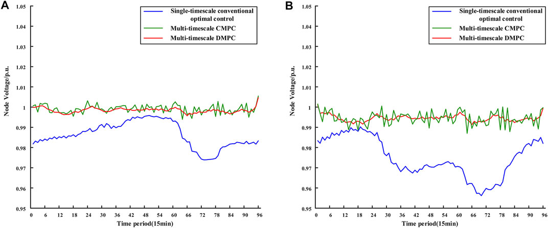
FIGURE 11. (A) Voltage control result of node 5. (B) Voltage control result of node 18.
6 Conclusion
In this paper, a collaborative Di-MPC-based source-grid-load active-reactive power coordinated voltage optimization control strategy is proposed. It considers the strong coupling characteristic of active and reactive power caused by the high R/X ratio of the islanded microgrid, as well as the difficulty of real-time online optimization and low robustness of the centralized method. The simulation case of a modified islanded microgrid is analyzed, and the results show that:
The proposed active-reactive power coordinated optimal control strategy can significantly reduce the system network losses. Furthermore, it gives priority to the consumption of wind power and photovoltaic when the load fluctuates, which reduces the wind power and photovoltaic curtailment and ensures the safe and economic operation of the islanded microgrid system.
The proposed collaborative Di-MPC-based voltage optimization control strategy can fully mobilize the voltage regulation potential of the source-grid-load triad, and it effectively suppresses the voltage deviation and fluctuations caused by the uncertainty of DGs and load demand.
From the perspective of modeling, this paper only considered the participation of conventional DGs in voltage regulation. In fact, multiple types of DG and other controllable device have already connected to the multi-energy system like microgrids, such as intelligent terminals, and electric vehicles, which are challenging to be considered in the optimization model. Therefore, more coordination possibilities by considering more DGs and controllable devices will be the research focus in our future work.
From the perspective of the collaboration mechanism, the proposed mechanism still needs some information interaction during the optimization process. This means that if there is any interaction failure appears or information losses, the real-time and robustness of the mechanism will be affected. Therefore, how to better deal with the failure and information losses during the interaction will be the research focus in our future work.
Data Availability Statement
The original contributions presented in the study are included in the article/Supplementary Material, further inquiries can be directed to the corresponding author.
Author Contributions
All authors listed have made a substantial, direct, and intellectual contribution to the research work and approved it for publication.
Funding
This research was funded by the Key-Area Research and Development Program of Guangdong Province (2019B111109001) and the National Natural Science Foundation of China (Grant No. 51761145106).
Conflict of Interest
The authors declare that the research was conducted in the absence of any commercial or financial relationships that could be construed as a potential conflict of interest.
Publisher’s Note
All claims expressed in this article are solely those of the authors and do not necessarily represent those of their affiliated organizations, or those of the publisher, the editors, and the reviewers. Any product that may be evaluated in this article, or claim that may be made by its manufacturer, is not guaranteed or endorsed by the publisher.
References
Baran, M. E., and Wu, F. F. (1989). Network Reconfiguration in Distribution Systems for Loss Reduction and Load Balancing. IEEE Trans. Power Deliv. 4, 1401–1407. doi:10.1109/61.25627
Fan, Z., Fan, B., and Liu, W. (2021). Distributed Control of DC Microgrids for Optimal Coordination of Conventional and Renewable Generators. IEEE Trans. Smart Grid 12, 4607–4615. doi:10.1109/TSG.2021.3094878
Ferrari-Trecate, G., Gallestey, E., Letizia, P., Spedicato, M., Morari, M., and Antoine, M. (2004). Modeling and Control of Co-generation Power Plants: a Hybrid System Approach. IEEE Trans. Contr. Syst. Technol. 12, 694–705. doi:10.1109/TCST.2004.826958
Gao, H., Liu, J., and Wang, L. (2018). Robust Coordinated Optimization of Active and Reactive Power in Active Distribution Systems. IEEE Trans. Smart Grid 9, 4436–4447. doi:10.1109/TSG.2017.2657782
Gómez, J. S., Llanos, J., Rute, E., Sáez, D., and Sumner, M. (2021). Distributed Predictive Control Strategy for Frequency Restoration of Microgrids Considering Optimal Dispatch. IEEE Trans. Smart Grid 12, 2748–2759. doi:10.1109/TSG.2021.3053092
Guo, Y., Gao, H., Wu, Q., Østergaard, J., Yu, D., and Shahidehpour, M. (2019). Distributed Coordinated Active and Reactive Power Control of Wind Farms Based on Model Predictive Control. Int. J. Electr. Power Energ. Syst. 104, 78–88. doi:10.1016/j.ijepes.2018.06.043
Han, H., Hou, X., Yang, J., Wu, J., Su, M., and Guerrero, J. M. (2016). Review of Power Sharing Control Strategies for Islanding Operation of AC Microgrids. IEEE Trans. Smart Grid 7, 200–215. doi:10.1109/TSG.2015.2434849
Hu, J., Shan, Y., Guerrero, J. M., Ioinovici, A., Chan, K. W., and Rodriguez, J. (2021). Model Predictive Control of Microgrids - an Overview. Renew. Sust. Energ. Rev. 136, 110422. doi:10.1016/j.rser.2020.110422
Jiayi, H., Chuanwen, J., and Rong, X. (2008). A Review on Distributed Energy Resources and MicroGrid. Renew. Sust. Energ. Rev. 12, 2472–2483. doi:10.1016/j.rser.2007.06.004
Katiraei, F., Iravani, R., Hatziargyriou, N., and Dimeas, A. (2008). Microgrids Management. IEEE Power Energ. Mag. 6, 54–65. doi:10.1109/MPE.2008.918702
Kouro, S., Cortes, P., Vargas, R., Ammann, U., and Rodriguez, J. (2009). Model Predictive Control-A Simple and Powerful Method to Control Power Converters. IEEE Trans. Ind. Electron. 56, 1826–1838. doi:10.1109/TIE.2008.2008349
Le, J., Liao, X., Zhang, Y., Chang, J., and Lu, J. (2020). Review and Prospect on Distributed Model Predictive Control Method for Power System. Automation Electric Power Syst. 44, 179–193.
Li, Y., Gao, D. W., Gao, W., Zhang, H., and Zhou, J. (2020). Double-Mode Energy Management for Multi-Energy System via Distributed Dynamic Event-Triggered Newton-Raphson Algorithm. IEEE Trans. Smart Grid 11, 5339–5356. doi:10.1109/TSG.2020.3005179
Li, Y., Wang, J., Wang, R., Gao, D. W., Sun, Q., and Zhang, H. (2021). A Switched Newton-Raphson-Based Distributed Energy Management Algorithm for Multienergy System under Persistent DoS Attacks. IEEE Trans. Automat. Sci. Eng., 1–13. doi:10.1109/TASE.2021.3104393
Liu, L., and Yang, G.-H. (2022). Distributed Optimal Energy Management for Integrated Energy Systems. IEEE Trans. Ind. Inf. 1, 1. doi:10.1109/TII.2022.3146165
Liu, W., Guo, P., Dan, Y., Cai, W., Wen, J., Xie, C., et al. (2016). Double -time Scale Reactive Power Control with Large-Scale Wind Power Integrated into Grid. Renew. Energ. Resour. 34, 1811–1818.
Liu, X., and Kong, X. (2013). Present Situation and Prospect of Model Predictive Control Application in Complex Power Industrial Process. Proc. CSEE 33, 79–85+14.
Maestre, J. M., Muñoz de la Peña, D., and Camacho, E. F. (2011). Distributed Model Predictive Control Based on a Cooperative Game. Optim. Control. Appl. Meth. 32, 153–176. doi:10.1002/oca.940
Mehmood, F., Khan, B., Ali, S. M., and Rossiter, J. A. (2021). Distributed MPC for Economic Dispatch and Intermittence Control of Renewable Based Autonomous Microgrid. Electric Power Syst. Res. 195, 107131. doi:10.1016/j.epsr.2021.107131
Morstyn, T., Hredzak, B., Aguilera, R. P., and Agelidis, V. G. (2018). Model Predictive Control for Distributed Microgrid Battery Energy Storage Systems. IEEE Trans. Contr. Syst. Technol. 26, 1107–1114. doi:10.1109/TCST.2017.2699159
Raimondi Cominesi, S., Farina, M., Giulioni, L., Picasso, B., and Scattolini, R. (2018). A Two-Layer Stochastic Model Predictive Control Scheme for Microgrids. IEEE Trans. Contr. Syst. Technol. 26, 1–13. doi:10.1109/TCST.2017.2657606
Sulc, P., Backhaus, S., and Chertkov, M. (2014). Optimal Distributed Control of Reactive Power via the Alternating Direction Method of Multipliers. IEEE Trans. Energ. Convers. 29, 968–977. doi:10.1109/TEC.2014.2363196
Villalón, A., Rivera, M., Salgueiro, Y., Muñoz, J., Dragičević, T., and Blaabjerg, F. (2020). Predictive Control for Microgrid Applications: A Review Study. Energies 13, 2454. doi:10.3390/en13102454
Wang, J., Zhang, Y., Wang, C., Xun, J., Jin, Z., Xu, F., et al. (2005). Power System Reactive Power/Voltage Assessment Based on Sensitivity Analysis and Optimal Power Flow. Power Syst. Tech., 65–69.
Wang, T., O'Neill, D., and Kamath, H. (2015). Dynamic Control and Optimization of Distributed Energy Resources in a Microgrid. IEEE Trans. Smart Grid 6, 2884–2894. doi:10.1109/TSG.2015.2430286
Xia, P., Liu, W., Zhu, D., Wang, N., and Hua, X. (2019). Multi-time Scale Optimal Control Method of Reactive Power and Voltage Based on Model Predictive Control. Electric Power Automation Equipment 39, 64–70.
Xu, F., Guo, Q., Sun, H., Lan, H., and Liu, X. (2015). Automatic Voltage Control of Wind Farms Based on Model Predictive Control Theory. Automation Electric Power Syst. 39, 59–67.
Yan, X., Xu, Y., Li, R., Jin, Y., and Li, T. (2019). Multi-Time Scale Reactive Power Optimization of Distribution Grid Based on Model Predictive Control and Including RDG Regulation. TRANSACTIONS CHINA ELECTROTECHNICAL SOCIETY 34, 2022–2037.
Yang, Q., Zhou, J., Chen, X., and Wen, J. (2021). Distributed MPC-Based Secondary Control for Energy Storage Systems in a DC Microgrid. IEEE Trans. Power Syst. 36, 5633–5644. doi:10.1109/TPWRS.2021.3078852
Zhang, Y., Ji, Y., and Tang, Y. (2017). Coordinated Control of Active and Reactive Power for Distribution Network with Distributed Photovoltaic Based on Model Predictive Control. Automation Electric Power Syst. 41, 140–146.
Zhang, Z., and Wang, J. (2016). An Active and Reactive Power Joint Real-Time Dispatch Approach for Microgrid Using Model Predictive Control. Proc. CSEE 36, 6743–6750+6928.
Zhao, Z., Guo, J., Lai, C. S., Xiao, H., Zhou, K., and Lai, L. L. (2021). Distributed Model Predictive Control Strategy for Islands Multimicrogrids Based on Noncooperative Game. IEEE Trans. Ind. Inf. 17, 3803–3814. doi:10.1109/TII.2020.3013102
Keywords: distributed model predictive control, coordinated optimization of active-reactive power, optimal control of voltage, islanded microgrid, collaborative method
Citation: Liu X, Du Z, Tan Y and Liu Y (2022) Voltage Optimization Control Strategy for Islanded Microgrid Source-Grid-Load Active-Reactive Power Coordination Based on Collaborative Di-MPC. Front. Energy Res. 10:880825. doi: 10.3389/fenrg.2022.880825
Received: 21 February 2022; Accepted: 31 March 2022;
Published: 26 April 2022.
Edited by:
Yan Xu, Nanyang Technological University, SingaporeReviewed by:
Yushuai Li, University of Oslo, NorwayYunhe Hou, The University of Hong Kong, Hong Kong, SAR China
Wenjie Zhang, National University of Singapore, Singapore
Copyright © 2022 Liu, Du, Tan and Liu. This is an open-access article distributed under the terms of the Creative Commons Attribution License (CC BY). The use, distribution or reproduction in other forums is permitted, provided the original author(s) and the copyright owner(s) are credited and that the original publication in this journal is cited, in accordance with accepted academic practice. No use, distribution or reproduction is permitted which does not comply with these terms.
*Correspondence: Zhaobin Du, ZXBkdXpiQHNjdXQuZWR1LmNu