 Jianhang Qian
 Zhijie Liu
 Ke-Jun Li
- School of Electrical Engineering, Shandong University, Jinan, China
This study presents a strategy to reduce the capacitance of the submodule (SM) capacitor of a modular multilevel converter-based medium-voltage wind power converter. The design of the SM capacitor of the modular multilevel converter (MMC) should consider the actual operating conditions, especially the influence of wind speed, because wind speed will affect the voltage ripple and voltage amplitude of the SM capacitor. In the traditional method, the capacitance design of the SM capacitor will be based on relatively high wind speed and leave a certain safety margin. However, in most cases, the system operates at the highest-frequency wind speed (HFWS). For the MMC-based wind energy conversion system, a constant capacitor voltage ripple (CCVR) control method is proposed. Using this method, the SM capacitor voltage ripple can be significantly reduced by injecting the second harmonic component of circulating current. In this way, the SM capacitor with smaller capacitance can be used. Finally, the effectiveness of the proposed method is validated in RT-Lab Platform.
1 Introduction
Energy and environmental problems are tied to human development. Conventional energy is non-renewable and can cause environmental pollution. The development of renewable energy, especially wind energy, has attracted more and more attention (Li et al., 2018; Ghosh et al., 2020; Yang et al., 2022). With the continuous progress of wind power generation technology, the capacity of wind energy conversion systems is also gradually increasing. At present, the mainstream wind power generation system of offshore wind farms has reached the megawatt level (Cortes-Vega et al., 2021; Xue et al., 2021). Compared with small-capacity wind turbines, large-capacity wind turbines have obvious advantages, such as low maintenance cost and stronger ability to capture wind energy. During the past 30 years, the size and capacity of the wind energy conversion system have exponentially increased. Some manufacturers have even started to develop wind energy conversion systems with a capacity of 10MWs (Rebello et al., 2019).
Permanent magnet synchronous generators (PMSGs) and full-scale power converters have been widely adopted in the megawatt wind power generation system (Tao et al., 2019; Khan et al., 2019). The gearbox, which is a part of a wind turbine, can be gotten rid of. It is known that the gearbox is prone to overload and has a high damage rate. Therefore, this kind of wind energy conversion has many advantages, such as high efficiency, low noise, long lifetime, low maintenance cost, and so on (Hu et al., 2020).
However, with the continuous increment of the capacity, the traditional two-level and three-level converter cannot meet the needs of high-capacity wind power generation systems. The increment of capacity promotes the development of the voltage level, and the medium voltage level has become the mainstream voltage level for turbines with rated power greater than 3.0 MW (Khanzadeh et al., 2021).
Compared with the traditional two voltage source converters, MMC has the following significant advantages (Xiao et al., 2021; Dekka et al., 2017).
(1) The change rate of bridge arm voltage and current is low, which reduces the impact of IGBT and other semiconductor devices in the switching transient process and ensures their safe and stable operation.
(2) For MMC with high voltage and large capacity, the number of SMs is large, the waveform of voltage step wave is good, the quality is high, the harmonic component is very low, and there is no need for filter.
(3) The modular structure is easy to expand and transform and can meet the needs of increasingly complex power systems and various engineering needs in practice.
With the progress of related technologies, MMC has been widely used in offshore wind power generation and high-voltage direct current (HVDC) technology (Ronanki and Williamson, 2018).
However, different from the traditional two-level and three-level converters, the capacitor of the MMC is not directly connected to the DC bus. Its capacitor is installed in the submodule (SM) (Li et al., 2022). During the operation of the MMC, the arm current will pass through the SM capacitors. This will cause the fluctuation of the capacitor voltage. Normally, the capacitor voltage ripple should not increase 10% of the nominal capacitor voltage; otherwise, the overvoltage can result in the breakdown of semiconductors and capacitors (Liu et al., 2019). As a result, the capacitor with large capacitance is usually required in the MMC. The large capacitor can increase not only the cost but also the space of the converter.
In this study, a constant capacitor voltage ripple (CCVR) control for MMC-based medium-voltage wind power converters is proposed. It is found that the SM capacitor voltage ripple can be suppressed by injecting the second harmonic component of circulating current; in this way, the capacitance of the SM capacitor can be reduced. Therefore, the following work is done in this study.
1) Through the analysis of the wind farm, it is found that there exists the most-frequency wind speed (MFWS) in the wind farm, and the MMC-based wind energy conversion system operates at this wind speed most of the time (Groch and Vermeulen, 2019). However, the capacitance of the SM capacitor is selected and designed under the maximum wind speed, which will cause a waste of cost and volume. Based on this, a new method regarding the capacitance of SM capacitor selection and design is proposed, that is, the capacitance of the SM capacitor will be selected under the MFWS. But, when the wind speed increases, the voltage ripple of the SM capacitor will also rise, so there exists a certain risk.
2) Injecting the second harmonic component of the circulating current into the MMC can reduce the voltage ripple of the SM capacitor, and the effect will be affected by the circulating current amplitude and phase angle. On the premise that the amplitude of the injected circulating current is fixed, the injection angle of the circulating current is changed, and it is found that under different wind speeds, each injected circulating current amplitude has an optimal angle. Under this optimal injection angle, the weakening effect on the SM capacitor voltage ripple is the largest.
3) Based on the above research conclusions, CCVR control for the MMC-based wind energy conversion system strategy is proposed. On the premise of the optimal injection phase angle, injecting the corresponding circulating current amplitude can keep the capacitor voltage ripple of the SM constant. Compared with the traditional method, the proposed method significantly reduces the SM capacitor voltage ripple. On the premise of the proposed method, the capacitance of the SM capacitor will be designed and selected under the MFWS, which greatly reduces the cost and volume of the equipment, and there is no need to worry about the SM capacitor damage caused by too high voltage ripple.
The rest of the article is organized as follows. The foundations of the MMC-based wind energy conversion system are explained in Section 2. The operation of wind farms is analyzed, and the concept of the most-frequency wind speed is put forward in Section 3. The relationship between circulating current injection and capacitor voltage fluctuation is analyzed in Section 4. Section 5 analyzes the influence of the amplitude and phase angle of the circulating current on the SM capacitor voltage ripple. Section 6 proposes a CCVR control for the MMC-based wind energy conversion system, and the effectiveness was analyzed using RT-Lab. The conclusions are summarized in Section 7.
2 Foundations
Figure 1 shows the diagram of the MMC-based wind energy conversion system. Under the action of blades, wind energy is converted into mechanical energy, which is then converted into electric energy through the PMSG. Finally, under the rectification of MMC, AC power is converted to DC power, and the electrical power is transferred from the PMSG to the DC bus (Singh et al., 1947; Ronanki and Williamson, 2018; Priya et al., 2019).
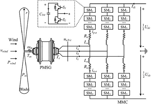
FIGURE 1. Diagram of the MMC-based wind energy conversion system.
In Figure 1, vwind is the wind speed. The wind energy determines the mechanical torque Tm and rotor speed ωm of the PMSG. The output voltage and current of the PMSG are denoted by ua(t) and ia(t), respectively. The currents in the upper and lower arms of the MMC are denoted by ip,a(t) and in,a(t), respectively, and ucap.ap(t) and ucap.an(t) are the capacitor voltage in the upper and lower arms, respectively.
In Figure 1, the wind speed is denoted by vwind. The wind energy determines the mechanical torque Tm and rotor speed ωm of the PMSG. Phase A is taken as an example. The output voltage and current of the PMSG are denoted by ua(t) and ia(t), respectively. The currents in the upper and lower arms of the MMC are denoted by ip,a(t) and in,a(t), respectively. The capacitor voltage in the upper and lower arms is denoted by ucap.ap(t) and ucap.an(t), respectively.
The frequency of the MMC connected to the PMSG is affected by the number of poles in the generator and is also affected by the mechanical angular speed, that is,
where ω is the angular speed of the MMC; ωr is the electrical angular speed of the rotor in the PMSG; p is the number of pole pairs.
The AC-side voltage and current of the MMC can be expressed as follows:
where Us is the amplitude of the output voltage and α is the phase angle of the output voltage; Is and β are the amplitude and the phase angle of the phase current.
In the wind energy conversion system, the relationship between the output current of the MMC and the electromagnetic torque of the PMSG can be expressed as in Eq. 3.
where id(t) and iq(t) denote the AC-side phase currents in the d-q frame.
From Eq. 3, the electromagnetic torque of the PMSG can be realized by controlling the output current of the MMC. To remove the coupling between the d-axis and q-axis currents, the d-axis current is controlled to be zero. Then Eq. 3 can be simplified to Eq. 4.
In Eq. 4, the electromagnetic torque is determined by the wind speed and the parameters of the wind turbine. Their relationship is shown in Eq. 5 (Jae-Jung Jung et al., 2015):
where ρ is the air mass density; A is the area covered by the wind blades; vwind denotes the wind speed; and Cp is the performance coefficient, which is determined by the pitch angle βpit and the tip-to-speed ratio λ.
To realize the maximum power point tracking (MPPT) of the wind energy system, Cp should be its maximum value, which is denoted by Cp.max. Thus, the reference value of output currents in the d-q frame can be derived, which is shown in Eq. 6.
where
where rwind is the radius of wind blades, and λopt is the optimum tip-to-speed ratio, which is a constant value and can be obtained from the manufacturer’s data.
The arm current of the MMC is composed of the DC component, phase current component, and circulating current component, which is shown in Eq. 8:
and
where Is and φ are the amplitude and the phase angle of phase current, respectively. Ic and θc are the amplitude and the phase angle of the second harmonic circulating current, respectively.
The modulation signal of the MMC is as follows:
where Adc is the DC component in the modulation signal; A1 and θ1 are the amplitude and the phase angle of the 1ω component in the modulation signal; and A2 and θ2 are the amplitude and the phase angle of the 2ω component in the modulation signal.
Taking the upper bridge arm as an example, the capacitor voltages can be derived by integrating the capacitor currents, which is as follows:
where Ucap.0 is the DC component in the capacitor voltage and CSM is the SM capacitor.
3 Mechanism of the Constant Capacitor Voltage Ripple Control Method
The design of the SM capacitor for the modular multilevel converter should consider the actual operating conditions, especially the influence of wind speed, because wind speed will affect the voltage ripple and voltage amplitude of the SM capacitor. In the traditional method, the design for the capacitance of the SM capacitor will be based on relatively high wind speed and leave a certain safety margin.
Figure 2 shows the wind speed fitting Weibull curve of a wind farm. It can be seen from the figure that the wind speed in this area is maintained at about 8 m/s most of the time. The wind speed with the highest frequency is defined as MFWS. In the traditional method, the capacitance of the SM capacitor is designed at the highest wind speed, but in the actual operating situation, the equipment operates at the MFWS most of the time, which will cause a waste. Based on this, a new capacitance of the SM capacitor design scheme is proposed, that is, the capacitance of the SM capacitor is selected under the MFWS instead of the highest wind speed, which will greatly reduce the volume and cost of the SM capacitor. However, doing so will create some problems.
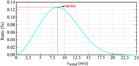
FIGURE 2. Wind speed–frequency distribution.
Figure 3 shows the change of SM capacitor voltage under different wind speeds. From Figure 3, the voltage ripple of the SM capacitor will rise with the increase in wind speed. Suppose the maximum wind speed of a wind farm is 12 m/s and the most-frequency wind speed is 8 m/s. In the traditional method, the capacitance of the SM capacitor is selected and designed under the working condition of vwind = 12 m/s, which can ensure the safe and reliable operation of the equipment. The proposed method is to select and design the capacitance of the SM capacitor under the working condition of vwind = 8 m/s. However, it can be seen from the figure that if it is designed according to the working condition of 8 m/s, the voltage ripple of the SM capacitor will increase and the risk of capacitor breakdown will occur at the high wind speed. Therefore, certain measures need to be taken to avoid the risk of breakdown of the SM capacitor due to high voltage ripple.
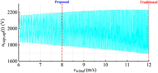
FIGURE 3. Capacitor voltage under different wind speeds.
Injecting the second harmonic component of the circulating current into the MMC can reduce the voltage ripple of the SM capacitor under certain conditions, so that the SM capacitor breakdown caused by the increase in voltage ripple can be avoided under the proposed method. The specific influence of the frequency doubling component of the injected circulating current on the capacitor voltage ripple will be discussed in the next section.
4 Effect of Circulating Current on Capacitor Voltage Ripple
The basic wind power control can be realized based on Eq. 6 and the proportional-integral (PI)-based current controller (Qingrui Tu et al., 2011), which is shown in Figure 4.
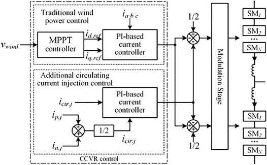
FIGURE 4. CCVR control for the MMC-based wind energy conversion system.
From the control block diagram shown in Figure 4, the CCVR control for the MMC is composed of two parts. They are the traditional wind power control and an additional circulating current injection control. The traditional wind power control is used to make the wind energy conversion system operate at the MPPT point to maximize conversion efficiency. The additional circulating current injection control is exclusive. Different from two-level converters, the arm current will pass through the SM capacitors in the MMC. With the effect of circular interaction, circulating currents will occur. These currents circulate inside the MMC, and they flow out from neither AC nor DC sides. Thus, the circulating current can provide a new control variable for improving the performance of the converter. The control of circulating current is similar to the control of output current. The reference value of the circulating current can be followed by using the PI-based current controller. Then, the problem is to calculate the appropriate value of the injected circulating current.
The reference value of the second harmonic component of circulating current will be calculated using the method proposed in the study by Liu et al. (2018). Figure 5 and Figure 6 show the variation of capacitor voltage ripple Uc,rip under the influence of different factors. Tables 1, 2 show the parameters of the MMC and the PMSG used in the numerical analysis. In Figure 5, the amplitude of circulating current, denoted by Ic, is 100A; the z-axis shows the values of Uc,rip with respect to the phase angle of circulating current and the wind speed. From Figure 5, changing the phase angle of the injected circulating current will have a great impact on the value of Uc,rip. This is because the injected circulating current can affect the phase angle of the harmonic components in capacitor voltage ripples. When the fundamental, 2nd, and 3rd harmonic components of the capacitor voltage reach the maximum at the same time, Uc,rip will be large. On the contrary, when the fundamental component reaches its maximum and the 2nd and 3rd harmonic components reach their minimum at the same time, the 2nd and 3rd harmonic components can offset part of the fundamental component; hence, Uc,rip can be smaller.
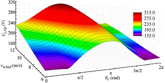
FIGURE 5. Values of capacitor voltage ripple under the different wind speeds and the different phase angles of circulating current.
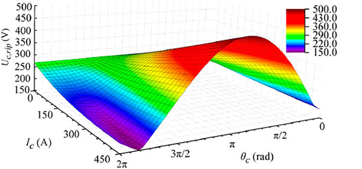
FIGURE 6. Values of capacitor voltage ripple under the different phase angles and different amplitudes of circulating current.
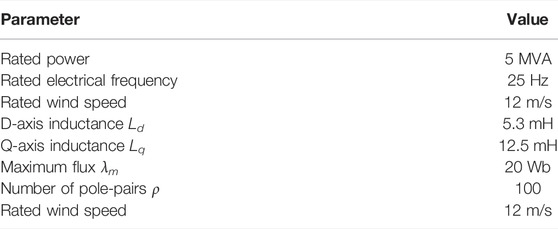
TABLE 1. Parameters of the PMSG.
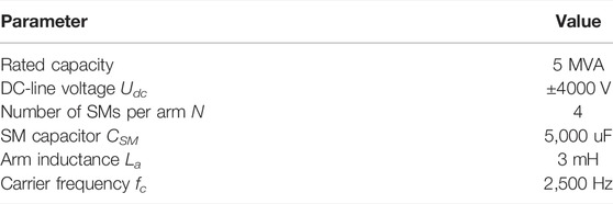
TABLE 2. Parameters of the MMC.
In Figure 6, vwind = 12 m/s, and the z-axis shows variation of capacitor voltage ripple Uc,rip under different phase angles and amplitudes of circulating current. With the increase in current amplitude, the influence of the circulating current on Uc,rip becomes greater. In addition, there always exists a phase angle in every circulating current amplitude, which can make Uc,rip smallest. In this study, this angle is defined as the optimum angle.
From Figure 5 and Figure 6, the following two conclusions can be made.
1) The injected circulating current can either reduce or increase the fluctuation magnitude of the capacitor voltage ripple. Thus, there can be numerous reference values of circulating current for suppressing capacitor voltage ripples. There should be a rule to choose the appropriate reference value.
2) The value of θc is the key to determining the effect of the injected circulating current. It can be seen from Figure 6 that the suppression effect occurs in a narrow interval. In other words, the angle of reference circulating current should be chosen precisely.
5 Phase Angle and Amplitude Analysis
5.1 Phase Angle Analysis
As mentioned earlier, every amplitude of circulating current has an optimum angle, which can make the injected circulating current have the best suppression effect on capacitor voltage ripples; hence, this optimum angle should be chosen as the phase angle of the reference circulating current.
This angle can be accurately obtained by following two steps. First, based on the steady-state analysis method proposed in the study by Liu et al. (2018), the values of Uc,rip are calculated when the circulating current angle is changed from 0 to 2π. Second, the minimum value of Uc,rip can be found, and the corresponding angle is the optimum angle.
Figure 7 shows the effect of the circulating current phase angle on capacitor voltage ripple under different wind speeds. In Figure 7A, A1, B1, C1, and D1 are the optimal injection phase angles at different wind speeds when the amplitude of injection circulating current is 135 A, respectively; A2, B2, C2, and D2 are the optimal injection phase angles at different wind speeds when the amplitude of injection circulating current is 165 A, respectively, in Figure 7B. The variation trend of capacitor voltage ripple under different circulating current phase angles can be seen from Figure 7, and there is an optimal injection phase angle under each wind speed and circulating current amplitude. Injecting circulating current under this phase angle can minimize the capacitor voltage ripple of the SM, and the phase angle is defined as the best phase angle under the corresponding wind speed and circulating current amplitude.
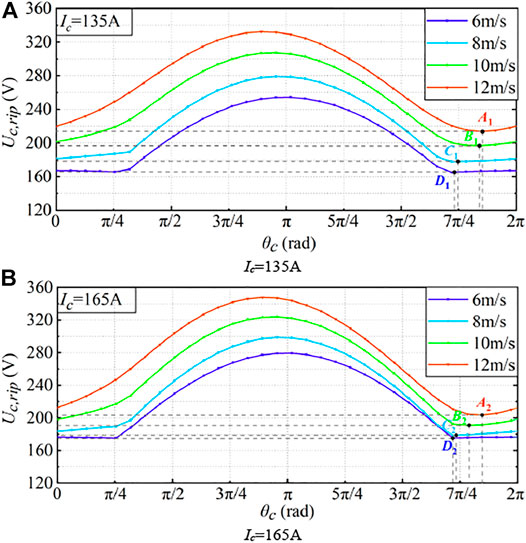
FIGURE 7. Capacitor voltage ripple under different circulating current phase angles. (A) Ic = 165 A. (B) Ic = 135 A.
Figure 8 shows the capacitor voltage ripple under different circulating current phase angles at the wind speed of 12 m/s, when the circulating current amplitude is 165 A. It can be seen that the angle of injecting circulating current has an obvious influence on the capacitor voltage ripple. In Figure 8, when the circulating current phase angle is 5.783, the capacitor voltage ripple is suppressed to 208.524 V. Therefore, under the condition of vwind = 12 m/s, when the circulating current amplitude is 165A, the corresponding optimal phase angle is 5.783.
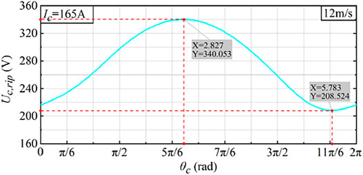
FIGURE 8. Capacitor voltage ripple under different circulating current phase angles when vwind = 12 m/s.
Based on the steady-state analysis method described in the study by Liu et al. (2018), the variation of capacitor voltage ripple can be analyzed by changing the amplitude and phase angle of circulating current at different wind speeds. In this way, the optimal circulating current phase angle under different operating conditions can be determined.
Figure 9 shows the corresponding optimal phase angle under different wind speeds when the circulating current amplitude is 135 and 165 A. Figure 9 also shows the variation trend of the circulating current phase angle; the change trend of the optimal phase angle decreases slowly at first and then increases to a certain extent. With the increase in circulating current amplitude, the wind speed at the corresponding turning point will also increase.
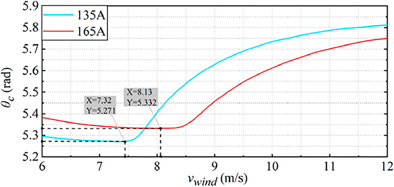
FIGURE 9. Optimal circulating current phase angle under different wind speeds.
Figure 10 shows the change of capacitor voltage ripple when injecting circulating current at the best phase angle. It can be seen from the figure that with the increase in wind speed, the effect of circulating current injection on the reduction of SM capacitor voltage ripple becomes more and more obvious, and the amplitude of circulating current will affect this effect. The effect of circulating current amplitude will be analyzed below.
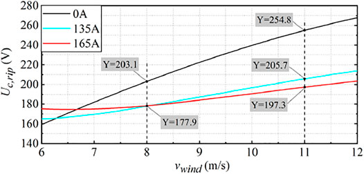
FIGURE 10. Capacitor voltage ripple at optimal phase angle under different wind speeds.
5.2 Amplitude Analysis
The optimal phase angle of the circulating current injection under different wind speeds and amplitudes is analyzed. After determining the optimal phase angle, the difference of the amplitude of the injected circulating current will also affect the capacitor voltage ripple.
Figure 11 shows the variation of capacitor voltage ripple with the amplitude of injected circulating current at different wind speeds under the optimal circulating current injection angle. It can be seen from the figure that at low wind speed, if the amplitude of injected circulating current is too large, it will cause an increase in capacitor voltage ripple; this also explains why increasing the amplitude of the circulating current will increase the SM capacitor voltage ripple at the wind speed of 6 m/s in Figure 10.
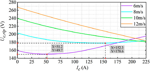
FIGURE 11. Capacitor voltage ripple under different circulating current amplitudes.
Based on the phase angle analysis and amplitude analysis of injection circulating current, the following conclusions can be obtained:
1) Injecting appropriate circulating current will suppress the voltage ripple of the submodule capacitor. The variation of amplitude and phase angle of circulating current will affect the capacitor voltage ripple.
2) Each circulating current amplitude will have and only have a corresponding optimal injection phase angle at different wind speeds. When injecting circulating current at this phase angle, the capacitor voltage ripple will be minimized.
3) The variation of circulating current amplitude will affect the capacitor voltage ripple. By changing the amplitude of the injected circulating current, the desired capacitor voltage ripple of the SM will be obtained.
6 Verifications
It can be seen from the previous section that the voltage ripple of the SM capacitor is affected by the phase angle and amplitude of the injection circulating current. The submodule capacitor voltage ripple can be controlled by changing the amplitude and phase angle of the injection circulating current. Based on this, a constant capacitor voltage ripple control method is proposed in this study. That is, on the premise of the optimal injection phase angle, the corresponding circulating amplitude is calculated to keep the capacitor voltage ripple constant.
Using this method, the SM capacitor can be designed and selected under the MFWS without worrying about the capacitor breakdown caused by the excessive voltage ripple of the SM capacitor, which can save the cost of the device and improve the reliability of the operation.
Simulations are conducted using RT-Lab to verify the effectiveness of the proposed method. The parameters of the PSMG and the MMC are shown in Tables 1, 2, respectively. The rated capacity of the wind generation system is 5 MVA.
Figure 12 shows the calculation results of the required injection circulating current amplitude under the optimal phase angle. According to the method mentioned in the study by Liu et al. (2018), the circulating current amplitude to be injected and the optimal phase angle can be calculated quickly.
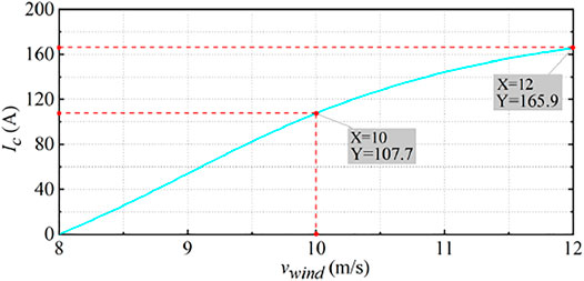
FIGURE 12. Calculation results of circulating current amplitude.
Figure 13 is the waveform diagram of the second harmonic component of circulating current icir.j(t).
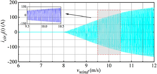
FIGURE 13. Actual injection circulating current waveform.
It can be seen that when vwind is large, it is necessary to inject a large amplitude of circulating current to keep the SM capacitor voltage ripple constant, which is consistent with the results of Figure 12.
Figure 14 shows the wind speed and system frequency. The wind speed is 6 m/s at 2 s. Then, the wind speed is increased from 6 m/s to 12 m/s during t = 2 s to t = 6 s.
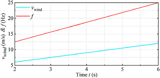
FIGURE 14. Wind speed and system frequency.
Figure 15 shows the capacitor voltage waveform under the traditional method. In Figure 15, the injected circulating current amplitude Ic is set to 0. This means that the circulating current is not injected. It can be seen that with the increase in wind speed, the voltage amplitude and voltage ripple of SM capacitor voltage will increase. When the wind speed reaches 12 m/s, the voltage amplitude and voltage ripple of the SM capacitor will also reach the maximum.
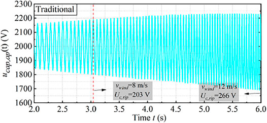
FIGURE 15. Capacitor voltage under the traditional method.
Figure 16 shows the capacitor voltage waveform under the proposed method.

FIGURE 16. Capacitor voltage under the proposed method.
In Figure 16, when the wind speed reaches 8 m/s, the second harmonic component of circulating current is injected to keep the capacitor voltage ripple constant. It can be seen from the figure that from 8 m/s, with the increase in wind speed, the amplitude of the capacitor voltage of the SM decreases to a certain extent, and the voltage ripple always remains a constant value.
Figure 17 shows the specific variation of the SM capacitor voltage ripple under the two methods. It can be seen from the figure that in the traditional method, the injected circulating current amplitude Ic is set to 0. This means that the circulating current is not injected. It can be seen that the capacitor voltage ripple is 203.09 V when the wind speed is 8 m/s. The capacitor voltage ripple increases with the increment of wind speed. The capacitor voltage ripple is 266 V when the wind speed is 12 m/s, and it reaches the maximum at this time. In the proposed method, the circulating current is injected at 8 m/s to keep the capacitor voltage ripple at a constant value. From the figure, the capacitor voltage ripple is effectively reduced. The capacitor voltage ripple is 203.09 V when the wind speed is 8 m/s; when the wind speed increases to 12 m/s, the capacitor voltage ripple is also 203.09 V, which is reduced by 23.65% compared with the traditional method (Wang et al., 2016). It is obvious that the proposed method is effective.
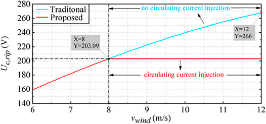
FIGURE 17. Comparison of SM capacitor voltage ripple under the two methods.
In conclusion, based on the method proposed in this study, the capacitance of the SM capacitor can be designed and selected at the MFWS, and the damage of the SM capacitor caused by too high capacitor voltage amplitude and capacitor voltage ripple can be avoided. Compared with the traditional method, SM capacitors with smaller capacitance will be used, so it can save the cost and reduce the volume of equipment.
In order to highlight the improvement of the work done in this study, similar work in the relevant literature is selected for comparison, which is divided into four cases. Case 1 is a two-level voltage source converter (Lachichi et al., 2019), case 2 is a traditional MMC system (Wang et al., 2016), and case 3 is the method proposed in this study. The comparison results are shown in Table 3.

TABLE 3. Comparison of different situations.
It can be seen from Table 3 that the MMC can be more suitable for medium- and high-voltage DC technology scenarios and has lower switching loss compared than the two-level converter; the method proposed in this study has lower requirements than the traditional MMC operation mode for the capacitance of submodules, which can reduce the operation cost of equipment.
7 Conclusion
This study proposed a CCVR control for the MMC-based wind energy conversion system. This method reduces the ripple of SM capacitor voltage by injecting the second harmonic component of circulating current into the MMC so that the capacitance of the SM capacitor can be selected and designed under the MFWS. The specific conclusions are summarized as follows:
(1) It is found that under the existing operating conditions, the capacitance design of the SM capacitor needs to be optimized. In this study, it is found that the voltage ripple of the SM capacitor can be significantly reduced by injecting the second harmonic component of circulating current. In this case, the design and selection for the capacitance of the SM capacitor will be carried out under the highest-frequency wind speed, and the cost and volume of the SM capacitor will be optimized.
(2) The second harmonic component of circulating current injection will affect the voltage ripple of the submodule capacitor, and at different wind speeds, the amplitude of each injected circulating current has the corresponding optimal phase angle, so that when the circulating current is injected at this phase angle, the capacitor voltage ripple of the SM will be minimized.
(3) A constant capacitor voltage ripple control method for the MMC-based wind energy conversion system is proposed; this method can significantly reduce the voltage ripple of the SM capacitor. The results show that the voltage ripple of the capacitor of the SM is significantly reduced by using the proposed method, that is, by 23.65%, compared with the traditional method under the working condition of vwind = 12 m/s.
Based on the method proposed in this study, the SM capacitor with smaller capacitance will be used, so the cost, volume, and weight of the capacitor will be reduced.
Data Availability Statement
The original contributions presented in the study are included in the article/Supplementary Material; further inquiries can be directed to the corresponding author.
Author Contributions
Conceptualization: JQ and ZL; writing—original draft preparation: JQ and ZL; writing—review and editing: ZL, LL, and ZG; visualization: JQ; supervision: ZL; and funding acquisition: ZL. All authors have read and agreed to the published version of the manuscript.
Funding
This work is supported by the Natural Science Foundation of Shandong Province under Grant ZR2021QE158.
Conflict of Interest
The authors declare that the research was conducted in the absence of any commercial or financial relationships that could be construed as a potential conflict of interest.
Publisher’s Note
All claims expressed in this article are solely those of the authors and do not necessarily represent those of their affiliated organizations, or those of the publisher, the editors, and the reviewers. Any product that may be evaluated in this article, or claim that may be made by its manufacturer, is not guaranteed or endorsed by the publisher.
References
Cortes-Vega, D., Ornelas-Tellez, F., and Anzurez-Marin, J. (2021). Nonlinear Optimal Control for PMSG-Based Wind Energy Conversion Systems. IEEE Lat. Am. Trans. 19 (7), 1191–1198. doi:10.1109/tla.2021.9461848
Dekka, A., Wu, B., Fuentes, R. L., Perez, M., and Zargari, N. R. (2017). Evolution of Topologies, Modeling, Control Schemes, and Applications of Modular Multilevel Converters. IEEE J. Emerg. Sel. Top. Power Electron. 5 (4), 1631–1656. doi:10.1109/jestpe.2017.2742938
Ghosh, S., Isbeih, Y. J., Bhattarai, R., Moursi, M. S. E., El-Saadany, E. F., and Kamalasadan, S. (2020). A Dynamic Coordination Control Architecture for Reactive Power Capability Enhancement of the DFIG-Based Wind Power Generation. IEEE Trans. Power Syst. 35 (4), 3051–3064. doi:10.1109/tpwrs.2020.2968483
Groch, M., and Vermeulen, H. J. (2019). Modeling High Wind Speed Shut-Down Events Using Meso-Scale Wind Profiles and Survival Analysis. IEEE Trans. Power Syst. 34 (6), 4955–4963. doi:10.1109/tpwrs.2019.2921940
Hu, C., Tong, Y., Jing, J., and Zhao, C. (2020). Research on Steady State Control Strategies of Wind Farm Integration by VSC-LCC Hybrid HVDC Transmission. Energy Rep. 6, 985–991. doi:10.1016/j.egyr.2020.11.088
Jae-Jung Jung, J. -J., Seung-Ki Sul, H. -J., and Sul, S. -K. (2015). Control Strategy for Improved Dynamic Performance of Variable-Speed Drives with Modular Multilevel Converter. IEEE J. Emerg. Sel. Top. Power Electron. 3 (2), 371–380. doi:10.1109/jestpe.2014.2323955
Khan, M. S. U., Maswood, A. I., Tariq, M., Tafti, H. D., and Tripathi, A. (2019). Parallel Operation of Unity Power Factor Rectifier for PMSG Wind Turbine System. IEEE Trans. Ind. Appl. 55 (1), 721–731. doi:10.1109/tia.2018.2870820
Khanzadeh, B., Okazaki, Y., and Thiringer, T. (2021). Capacitor and Switch Size Comparisons on High-Power Medium-Voltage DC–DC Converters with Three-phase Medium-Frequency Transformer. IEEE J. Emerg. Sel. Top. Power Electron. 9 (3), 3331. doi:10.1109/JESTPE.2020.2999726
Lachichi, A., Junyent-Ferre, A., and Green, T. C. (2019). Comparative Optimization Design of a Modular Multilevel Converter Tapping Cells and a 2L-VSC for Hybrid LV Ac/dc Microgrids. IEEE Trans. Ind. Appl. 55 (3), 3228–3240. doi:10.1109/tia.2019.2897263
Li, W., Chao, P., Liang, X., Xu, D., and Jin, X. (2018). An Improved Single-Machine Equivalent Method of Wind Power Plants by Calibrating Power Recovery Behaviors. IEEE Trans. Power Syst. 33 (4), 4371–4381. doi:10.1109/tpwrs.2017.2771323
Li, Z., Bo, L., Bai, J., Yang, B., and Zhu, D. (2022). Suppression Control Strategy of MMC Sub-module Capacitor Voltage in Variable-Frequency Situation. Energy Rep. 8, 1191–1206. doi:10.1016/j.egyr.2021.12.055
Liu, Z., Li, K.-J., Wang, J., Javid, Z., Wang, M., and Sun, K. (2019). Research on Capacitance Selection for Modular Multi-Level Converter. IEEE Trans. Power Electron. 34 (9), 8417–8434. doi:10.1109/tpel.2018.2886219
Liu, Z., Li, K., Sun, Y., Wang, J., Wang, Z., Sun, K., et al. (2018). A Steady-State Analysis Method for Modular Multilevel Converters Connected to Permanent Magnet Synchronous Generator-Based Wind Energy Conversion Systems. Energies 11 (2), 461. doi:10.3390/en11020461
Priya, M., Ponnambalam, P., and Muralikumar, K. (2019). Modular‐multilevel Converter Topologies and Applications - a Review. IET Power Electron. 12 (2), 170–183. doi:10.1049/iet-pel.2018.5301
Qingrui Tu, Q., Lie Xu, Z., and Xu, L. (2011). Reduced Switching-Frequency Modulation and Circulating Current Suppression for Modular Multilevel Converters. IEEE Trans. Power Deliv. 26 (3), 2009–2017. doi:10.1109/tpwrd.2011.2115258
Rebello, E., Watson, D., and Rodgers, M. (2019). Performance Analysis of a 10 MW Wind Farm in Providing Secondary Frequency Regulation: Experimental Aspects. IEEE Trans. Power Syst. 34 (4), 3090–3097. doi:10.1109/tpwrs.2019.2891962
Ronanki, D., and Williamson, S. S. (2018). Modular Multilevel Converters for Transportation Electrification: Challenges and Opportunities. IEEE Trans. Transp. Electrific. 4 (2), 399–407. doi:10.1109/tte.2018.2792330
Singh, B., Kumar, N., and Panigrahi, B. K. Steepest Descent Laplacian Regression Based Neural Network Approach for Optimal Operation of Grid Supportive Solar PV Generation. IEEE Trans. Circuits Syst. II Express Briefs 68 (6), 1947
Tao, S., Zhao, L., Liao, K., and Liu, Y. (2019). Probability Assessment of Characteristics of Sub-synchronous Oscillation in D-PMSG-Based Wind Power Generation System. IEEE Access 7, 133159–133169. doi:10.1109/access.2019.2941909
Wang, M., Hu, Y., Zhao, W., Wang, Y., and Chen, G. (2016). Application of Modular Multilevel Converter in Medium Voltage High Power Permanent Magnet Synchronous Generator Wind Energy Conversion Systems. IET Renew. Power Gener. 10 (6), 824–833. doi:10.1049/iet-rpg.2015.0444
Xiao, H., Sun, K., Pan, J., Li, Y., and Liu, Y. (2021). Review of Hybrid HVDC Systems Combining Line Communicated Converter and Voltage Source Converter. Int. J. Electr. Power & Energy Syst. 129, 2021. doi:10.1016/j.ijepes.2020.106713
Xue, T., Lyu, J., Wang, H., and Cai, X. (2021). A Complete Impedance Model of a PMSG-Based Wind Energy Conversion System and its Effect on the Stability Analysis of MMC-HVDC Connected Offshore Wind Farms. IEEE Trans. Energy Convers. 36 (4), 3449–3461. doi:10.1109/tec.2021.3074798
Yang, D., Jin, Z., and Zheng, T. (2022). An Adaptive Droop Control Strategy with Smooth Rotor Speed Recovery Capability for Type III Wind Turbine Generators. Int. J. Electr. Power. Energy Syst. 135, 2022. doi:10.1016/j.ijepes.2021.107532
Nomenclature
MMC Modular multilevel converter
CCVR Constant capacitor voltage control
SM Submodule
MFWS Most frequency wind speed
PMSG Permanent magnet synchronous generator
HVDC High-voltage direct current
Symbols
vwind Wind speed
Tm Mechanical torque of PMSG
ωm Rotor speed of PMSG.
ua(t), ia(t) Output voltage and current of PMSG
ip,a(t), in,a(t) Instantaneous value of the upper and lower arm currents in phase A, respectively
ucap.ap(t), ucap.an(t) Instantaneous value of the upper and lower capacitor voltages in phase A, respectively
ω Angular speed of MMC
P Number of pole pairs
Us Amplitude of the output voltage
α Phase angle of the output voltage
Is Amplitude of the phase current Amplitude of phase current
β Phase angle of the phase current
id(t), iq(t) Instantaneous value of the ac-side phase currents in d-q frame
Te(t) Electromagnetic torque of PMSG
Ld, Lq D-axis and q-axis inductance
Ρ Air mass density
A Area covered by the wind blades
Cp Performance coefficient
βpit Pitch angle
λ Tip-speed ratio
id.ref, iq.ref Reference value of output currents in the d-q frame
rwind Radius of wind blades
λopt Optimum tip-speed ratio
Is Amplitude of the phase current Amplitude of phase current
φ Phase angle of phase current
abrIc Amplitude of the second harmonic circulat-ing current
θc Phase angle of the second harmonic circulat-ing current
Adc Dc component in the modulation signal
A1 Amplitude of 1ω component in the modulation signal
θ1 Phase angle of 1ω component in the modulation signal.
A2 Amplitude of 2ω component in the modulation signal
θ2 Phase angle of 2ω component in the modulation signal
Ucap 0 Dc component in the capacitor voltage
CSM Submodule capacitor of MMC
Keywords: modular multilevel converter, most frequency wind speed, capacitor voltage ripple, wind energy conversion, circulating current
Citation: Qian J, Liu Z, Li K-J, Li L and Guo Z (2022) Reducing Submodule Capacitance for Modular Multilevel Converter-Based Medium-Voltage Wind Power Converter. Front. Energy Res. 10:883004. doi: 10.3389/fenrg.2022.883004
Received: 24 February 2022; Accepted: 19 April 2022;
Published: 23 May 2022.
Edited by:
Sudhakar Babu Thanikanti, Chaitanya Bharathi Institute of Technology, IndiaReviewed by:
Mohamed Salem, Universiti Sains Malaysia (USM), MalaysiaNishant Kumar, National University of Singapore, Singapore
Copyright © 2022 Qian, Liu, Li, Li and Guo. This is an open-access article distributed under the terms of the Creative Commons Attribution License (CC BY). The use, distribution or reproduction in other forums is permitted, provided the original author(s) and the copyright owner(s) are credited and that the original publication in this journal is cited, in accordance with accepted academic practice. No use, distribution or reproduction is permitted which does not comply with these terms.
*Correspondence: Zhijie Liu, bGl1empAc2R1LmVkdS5jbg==