 Yanping Wang
 Weiqin Li1
 Tielin He
 Zucao Zhu
- 1Key Laboratory of Fluid Transmission Technology of Zhejiang Province, Zhejiang Sci -Tech University, Hangzhou, China
- 2Zhejiang Province Institute of Metrology, Hangzhou, China
A centrifugal pump is an important solid–liquid mixture conveying machinery, which is widely used in mineral mining, water conservancy engineering, and other fields. Solid particles will wear the impeller of the centrifugal pump in the process of transportation, resulting in lower service life of the impeller, especially in the transportation of a high concentration of solid particles. Many scholars use numerical simulation to study the wear of centrifugal pumps, but few efforts have been made in the wear experiment. In this study, the effect of three factors, namely, diameter of solid particles, mass concentration of particles, and material of impellers on the wear of a solid–liquid two-phase centrifugal pump was studied by the wear experiment. The solid particles are SiO2 with irregular shapes, and the diameter ranges are 0.125–0.212 mm, 0.212–0.425 mm, and 0.425–0.710 mm. The mass concentration of solid particles is 15%, 20%, and 30%. The material of impellers is carbon structural steel (Q235), gray cast iron (HT200), and low-alloy high-strength steel (16 Mn). The amount of wear is determined by measuring the thickness of the impeller material before and after wear experiments. The wear morphology of the impeller was observed by using a digital microscope. The results showed that the wear mainly concentrated on the middle and trailing edges of the blade. Impellers of different materials suffer different wear forms, among which the impeller made of HT200 has the best erosion resistance. The increase of solid mass concentration will aggravate the wear of the impeller. The change of particle diameters also has a great influence on impeller wear.
Introduction
Erosion wear of centrifugal pumps widely exists in the transportation, aerospace, chemical, mining, environmental protection, and other industries. Erosion wear generally refers to the hard sand with a certain kinetic energy that repeatedly impacts and cuts the surface of flow-through parts of the hydraulic machinery and results in mass loss, which is a very important cause of equipment failure or damage. The erosion wear results in the decrease of centrifugal pump efficiency, which will cause direct economic loss and energy waste.
Many scholars have studied erosion wear caused by solid–liquid two-phase flow. Tarodiya et al. (Tarodiya and Gandhi, 2019) carried out experiments on two kinds of sand mud of equal size at two pump speeds and two flows and examined the SCANNING electron microscopy (SEM) images of wear samples, and the results showed that the wear at the volute tongue was caused by both cutting and deformation. Bozzini et al. (2003) simulated the particle’s motion trajectory and collision velocity in the pipeline and deduced the erosion model parameters based on the experiment. Azimian et al. (Azimian and Bart, 2015) conducted experiments on the centrifugal rotary wear equipment and found that the size of erosion pits increases with the increase in sediment concentration. Walker et al. (Walker and Bodkin, 2000) summarized the influence of solid particle size, solid–liquid two-phase fluid concentration, and the rotation speed of the pump on wear and explained the wear rule. Amaro et al. (2020) studied the effect of different impact angles, impact distances, and particle sizes on the impact fatigue life. Peng et al. (Guangjie et al., 2013) studied the relationship between blade surface wear rate and sediment concentration and obtained the distribution rule of the blade surface wear rate. Islam et al. (Islam and Farhat, 2014) carried out an erosion test on APL-X42 steel to study its erosion wear performance under different erosion angles. Feng et al. (2020) tested and analyzed WC-CO cemented carbide and found that the anti-erosion performance of cemented carbide decreased with the increase in WC grain size and Co content. Liu et al. (2004) studied the erosion wear of the centrifugal mud pump and the abrasion resistance of a new kind of anti-erosive wear material (Al2O3) through experiments. The results showed that wear of the pressure surface is more serious than that of the suction surface. Compared with cast iron (FC20) and AISI 1316L stainless steel, Al2O3 had excellent anti-wear performance. Walker et al. (Walker and Robbie, 2013) measured the wear resistance of natural rubber, eutectic, and hypereutectic white cast iron under the conditions of erosion wear and compared the results with the wear of the materials in a centrifugal slurry pump in a factory. In laboratory experiments, the wear rate of hypereutectic white cast iron is higher than that of eutectic white cast iron, and the wear rate of natural rubber is much lower than that of eutectic white cast iron. The aforementioned laboratory results are the opposite of the field trial results. Walker believed that the aforementioned difference is largely due to particle impact energy or impingement angle and particle shape or size. Xiong et al. (2013) carried out experimental studies on erosion wear of Ti(C, N)-Mo2C-Co cermet in artificial seawater containing SiO2 solid particles. The results showed that the adhesive phase began to wear at first and gradually expanded and fractured. Nguyen (Nguyen et al., 2014) conducted slurry erosion tests on SUS-304 stainless steel. The results showed that the corrosion rate is high at the beginning and gradually decreases as the test time goes on. Arabnejad et al. (2015) studied the impact of particle hardness on the erosion of stainless steel at low impact velocity and found that the erosion rate increased with the increase of particle hardness. Shah and Jain (Shah and Jain, 2008) used computational fluid dynamics (CFD) and studied the relationship between erosion rate and flow velocity, slurry concentration, proppant (solid particle) size, and density. The results showed that the slurry flow rate was the most important factor affecting erosion, and the slurry concentration and fluid viscosity had a greater influence on the erosion rate. Shen et al. (2016) used computational fluid dynamics (CFD) to study the wear of the screw centrifugal pump when the transmission medium is solid–liquid two-phase flow with large-size particles. The research results showed that the volume fraction of the solid phase has a greater impact on the trajectory when transporting large particles, while for small particles, it has little effect. Prasanna et al. (2018) successfully sprayed Stellite-6, 10%Al2O3+90%CoCrTaY, and 25%Cr3C2-20(Ni-Cr)+75%NiCrAlY on three kinds of turbine alloys: Ti-6Al-4V, Co-based superalloy (Super Co 605), and Fe-based special steel (MDN121). The microstructure and mechanical properties of the coating were characterized. The research results showed that the relative corrosion resistance of various coatings can be arranged in the following order: Stellite-6> Cr3C2-20(Ni-Cr)+75%NiCrAlY > Al2O3+90%CoCrTaY. Iwai et al. (Iwai and Nambu, 1997) conducted tests on 13 kinds of materials, including polymers, metals, and ceramics, and found that among these materials, rubber had the best wear resistance and polyurethane had the worst. Bansal et al. (2020) used different influencing factors, namely, average erodent particle size, slurry concentration, impact angle, and impact velocity to test the anti-erosion performance of coated and uncoated SS410 steel and analyzed the effect of the thickness of the hydrophobic coating on the anti-erosion performance. The results showed that the PTFE coating with the smallest thickness had the lowest corrosion rate compared with similar coatings. Medvedovski et al. (Medvedovski and Antonov, 2020) tested the iron boride coatings and carbon steel commonly used in industry and observed the erosion surface using a scanning electron microscope. All test results showed that the performance of iron boride coatings is better than that of carbon steel. The erosion mechanism of carbon steel is determined by plastic deformation and ploughing, and the erosion mechanism of iron boride coatings is related to microcracks such as in many advanced ceramics. Singh et al. (2019) studied the erosion performance of ceramic-reinforced WC–10Co4Cr cermet coatings under different parameters. The microstructure analysis showed that there were interlocked lamellae splats, pores, and unmelted particles on the sprayed surface, and it has good anti-erosion performance in a weakly acidic environment. Grant et al. (Grant and Tabakoff, 1975) verified the erosion wear prediction model that was established on the basis of considering the aerodynamic resistance of solid particles, rebound dynamics of wall surface, and material removal process. The predicted erosion wear amount and erosion wear location of blades are almost consistent with those of the tested. Dong et al. (Xing et al., 2009) analyzed the position and process of pump wear through simulation and experiment and found that the impact of pulverized coal with a certain diameter, shape, impact velocity, and invasion angle on the flowing parts would produce pits on the surface of the flowing parts. Lai et al. (2019) combined the rebound model and erosion model proposed by Grant and Tabakoff to study the erosion wear problem of solid particles in a solid–liquid two-phase centrifugal pump. The results showed that the maximum erosion rate occurred at the impeller hub, and the most serious erosion area of the blade was located at the leading edge between 55° and 60° curvature angle. Liu et al. (Liu and Zhu, 2011) analyzed the wear characteristics of the impeller of the centrifugal sewage pump and proposed measures to reduce the wear of the impeller. The research results can provide theoretical reference for the optimal design of the centrifugal sewage pump. Ojala et al. (2016) revealed the behavior differences of different materials under mud erosion conditions. The wear surface analysis shows that relative wear properties of steel increase with the increase of abrasive size, while the relative wear properties of elastomer decrease with the increase of abrasive size. Marshall et al. (Marshall, 2009) reviewed the forces and torques applied to particles by fluid motion, particle–particle collision, and van der Waals forces. The effects of different parameters on the normal collision and adhesion of two particles are studied in detail. Ovchinnikov et al. (2019) proposed a calculation method for the maximum metal consumption loss of the impeller of a single-stage centrifugal pump, and the results show that this method can effectively reduce the residual deformation risk of the pump shaft. Oka et al. (2005) proposed an equation that can predict the impact wear of solid particles, which is applicable to any impact condition and any type of material. Through erosion experiments on several materials, the results show that the erosion damage is related to the initial hardness, plastic deformation characteristics, or brittleness of materials. Boon et al. (Ng et al., 2008) conducted a numerical simulation on dense solid–liquid two-phase flow and found that particle friction is an important factor in establishing the constitutive equation of dense particle flow. Aslfattahi et al. (2020) used nanomaterials (MXene) with the chemical formula Ti3C2 together with silicone oil for the first time to improve the thermophysical properties of Mxene-based silicone oil. Das et al. (2021) and Rubbi et al. (2021) reviewed the applications of ionic liquids and ionic fluids in different solar systems and the latest progress of nanoparticles in solar systems. Samylingam et al. (2020) synthesized nanomaterials (MXene) with the chemical formula Ti3C2 by the wet chemistry method, suspended its suspension in pure oil palm oil (OPO), and prepared a new type of heat transfer fluid. Kadirgama et al. (2021) used nanomaterials (MXene) and ethylene glycol (EG) as the base liquid to prepare a homogeneous mixture of nanofluids with good optical properties, which might enable high optical performance applications in the solar system.
Most of the abovementioned research studies are based on the condition of large particles and low concentration, but a few research studies on the wear of high-concentration fine particles on the centrifugal pump are carried out experimentally. However, the collision frequency of dense fine particles with a wall surface is much higher than that of large particles, resulting in different wear characteristics. In order to enrich the wear research of centrifugal pumps under the condition of dense fine particles, the wear tests of the solid–liquid two-phase centrifugal pump impeller under different high mass concentrations, fine particle diameters, and impeller materials were carried out in this study.
Experimental Apparatus and Method
Figure 1 shows the schematic diagram of the wear experimental system, while parameters of the main components related to the experimental system are shown in Table 1. The pressure sensor and electromagnetic flow sensor are used to monitor the centrifugal pump operation during the test. The running time is 72 h per test, and the rotation speed r = 1450 rpm. The valve is adjusted to ensure that the inlet flow reaches the rated flow of 16 m3/h. The impellers of the tested pump were made of three materials, namely, carbon structural steel (Q235), gray cast iron (HT200), and low-alloy high-strength steel (16 Mn). The major properties of the three materials are shown in Table 2. Considering economy, universality, and no pollution, SiO2 particles were chosen as solid components with 2650 kg/m3 density and 475 MPa Brinell hardness, and the particle diameter ranges are 0.125–0.212 mm, 0.212–0.425 mm, and 0.425–0.710 mm, as shown in Figure 2.
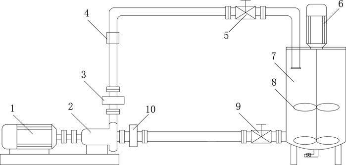
FIGURE 1. Schematic diagram of the experimental system. 1- Electrical machinery, 2- Test prototype pump, 3- Outlet pressure sensor, 4- Electromagnetic flowmeter, 5- Outlet valve, 6- Agitator motor, 7-Agitator tank, 8- Agitator, 9-Inlet valve, 10-Inlet pressure sensor.
TABLE 1. Main component parameters of the experimental system.
TABLE 2. Basic properties of metal impeller materials.
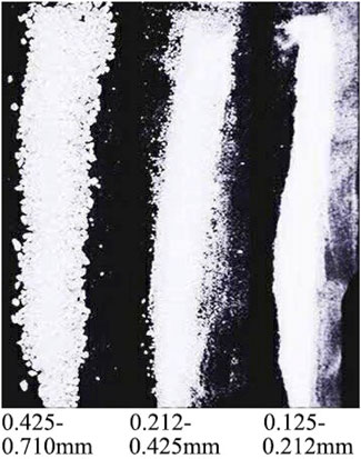
FIGURE 2. Particle morphology.
An ultrasonic thickness gage (Figure 3A) was used to measure the thickness of the blade. The wear loss of the blade is expressed by the variation of blade thickness at the measuring position before and after the wear experiment, namely,
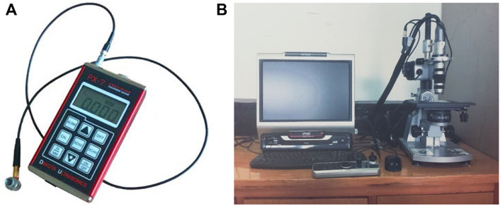
FIGURE 3. (A) Ultrasonic thickness gauge; (B) Digital microscope.
As shown in Figure 4, the blades of the experiment impeller (Figure 4A) are numbered 1 to 5, the seventeen measuring points are evenly arranged on the pressure surface of each blade, and the longitudinal distance of each measuring point is 5 mm; the transverse distance is 10 mm (Figure 4B).
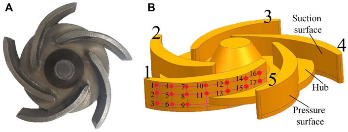
FIGURE 4. (A) Experiment impeller; (B) Measuring point on the impeller model.
Results and Discussion
Many scholars (Walker and Bodkin, 2000; Liu et al., 2004; Guangjie et al., 2013) have found that the wear of the impeller pressure surface is much more serious than that of the suction surface. This is because the density of particles is higher than that of water, and they tend to gather at the pressure surface end under the action of centrifugal force. Therefore, this work mainly analyzes the wear of impeller pressure surface by measuring point data, wear morphology, and electron microscope observation.
Influence of Mass Concentration on Impeller Erosion Wear
This section analyzes the influence of mass concentration on impeller erosion wear. The experiment was conducted under mass concentrations of solid 15, 20, and 30%, the material of impellers is Q235, and the solid particle diameter is 0.125–0.212 mm.
Figure 5 shows the mean value of blade thickness at the measuring point corresponding to different mass concentrations. It can be seen that the wear loss increases with the increase in concentration, but there is no linear relationship, which is consistent with the numerical simulation results of Lai (Lai et al., 2019) and Noon (Liu and Zhu, 2011).
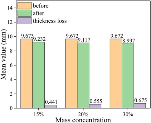
FIGURE 5. Mean thickness of the blade at the measuring point related with different mass concentrations.
Figures 6, 7 show the surface condition of the impeller after the wear experiment. The parts in the red circle are the parts with obvious wear (same in the following). It can be seen that the middle and tail sections of the pressure surface are the most severely worn parts. This is because the rotating movement of the impeller produces centrifugal force, which induces the particles to move along the pressure surface to the volute, and in this process, the particles have a cutting effect on the pressure surface. As the mass concentration increases, the wear on the pressure surface of the impeller gradually increases, especially at the tail of the blade; at the same time, the wear area expands.
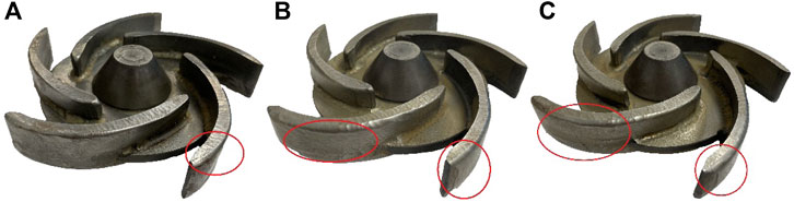
FIGURE 6. Blade wear under different mass concentration. (A) 15%, (B) 20%, and (C) 30%.
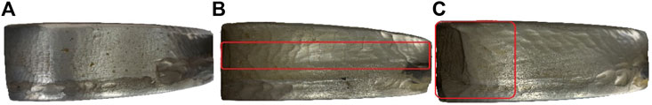
FIGURE 7. Pressure surface wear under different mass concentration. (A) 15%, (B) 20%, and (C) 30%.
Figure 8 shows that the thickness variation at the measuring point is related to the different mass concentration. The wear is more serious at the middle and trailing edge of the blade; this is because the solid particles are affected by the vortex flow in the middle and tail section of the impeller passage, resulting in the impact of solid particles on the pressure surface. Therefore, the wear on this area will be affected by the combined impact damage and cutting damage, which could lead to the wear increase.
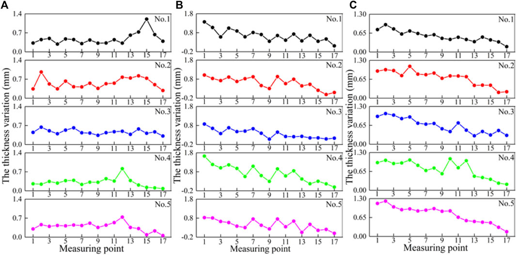
FIGURE 8. Thickness variation of the blade at measuring points related with different mass concentrations (A) 15% mass concentrations, (B) 20% mass concentrations, and (C) 30% mass concentrations.
In Figure 8A, from point 1 to point 11 of the No. 1 blade, the wear loss fluctuates around 0.4 mm. Along the axial direction of the impeller, the wear of the middle area of the blade (the position of points 2, 5, 8, and 11) is more serious than that of both ends of the blades (the position of points 1, 4, 7, 3, 6, and 9).
It can be seen from Figure 8B that the wear of the trailing edge of the blade is more serious. Along the axial direction of the impeller, the upper edge of the blade (the position of points 1, 4, 7, 10, 12, 14, and 16) is more worn. At some measuring points (the positions of point 16 of the No. 2 blade and point 17 of the No. 4 blade), the thickness variation is negative. The main reason is that the area is close to the head of the blade, and impact wear is more serious than sliding wear, so it is more likely to produce an “extrusion lip”.
Figure 8C shows that thickness variation at the position of the measuring point when the mass concentration is 30%, which expresses that the wear of the trailing edge of the blade is more serious. Along the axial direction of the impeller, the wear in the middle of the blade (the position of points 2, 5, 8, and 11) is more serious than that of both ends. From point 1 to point 14, the wear loss of each blade is greatly different, while from point 14 to point 17, the wear loss of each blade is nearly similar.
According to Figure 8, the thickness variation at the measuring point of each blade in the same impeller is very close. When the mass concentration is 20 and 30%, the thickness variation value from the head of the blade to the trailing edge of the blade tends to increase, which is due to the secondary flow generated near the trailing edge of the blade when the mass concentration is higher. The secondary flow causes solid particles to scour the blade surface repeatedly, which leads to increased wear. The secondary flow is relatively small when the mass concentration is 15%. This result is consistent with the numerical simulation results of Dong Xing (Xing et al., 2009).
Influence of Solid Particle Diameters on Impeller Erosion Wear
This section analyzes the influence of solid particle diameters on impeller erosion wear. The experiment was conducted under the solid particle diameter 0.125–0.212 mm, 0.212–0.425 mm, and 0.425–0.710 mm. The mass concentration of solid is 30%, and the material of impellers is Q235.
As can be seen from Figure 9, when the particle size is 0.212–0.425 mm, the variation of blade thickness is the largest. When the solid particle diameter is 0.425–0.710 mm, the variation of blade thickness is the minimum. As the particle diameters increase, the wear first increases and then decreases. The reason for this result is related to the “size effect” of particles. At the condition of higher mass concentration, the increase of particle diameters will lead to decrease in the number of particles in per unit volume, which causes the decrease of impact between particles and blade surface. The “size effect” of the particles can reduce the wear.
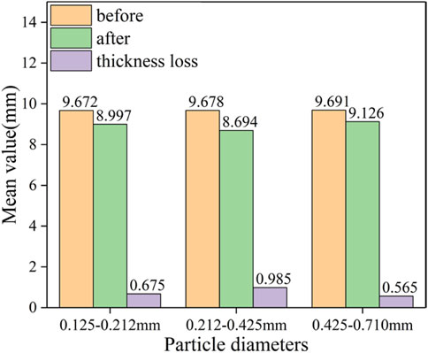
FIGURE 9. Mean value of blade thickness at the measuring point related with different particle diameters.
From Figure 10, with the increase of the solid particle size, the wear of the blade near the front cavity increases, and the wear of the hub surface increases. That is because the larger the particle size of the solid particles, the greater the momentum and inertial force of the solid particles. When the particles enter the cavity of the centrifugal pump, the velocity component of the particles in the circumferential direction is smaller, which will directly impact the hub.
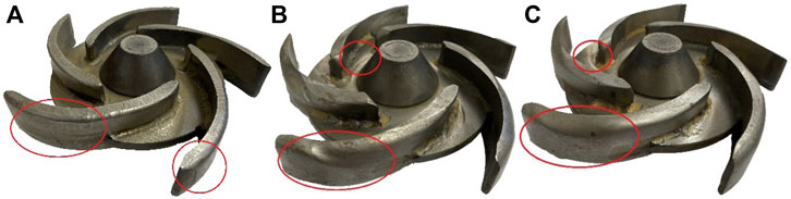
FIGURE 10. Blade wear under different particle sizes. (A) 0.125–0.212 mm, (B) 0.212–0.425 mm, and (C) 0.425–0.710 mm.
According to Figure 11, the wear of the pressure surface of the blade is more serious, and it is concentrated at the tail and middle part of the pressure surface. The reason for this phenomenon is that the larger the particle size, the greater is the inertia that will cause the particles to move to the tail of the pressure surface, which will eventually cause more serious wear on the blade surface; as the particle size increases, the wear of the pressure surface of the blade has a tendency to spread to the head of the blade. The area where the pressure surface of the blade is close to the front cavity side is more severely worn. The reason is that the experimental prototype pump is an open impeller, and the internal flow channel will produce a split, which will cause serious wear on the edge of the blade. When the particle size is 0.212–0.425 mm, the wear of the pressure surface is more severe than when the particle size is 0.125–0.212 mm and 0.425–0.710 mm.
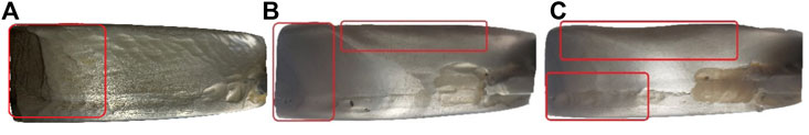
FIGURE 11. Pressure surface wear under different particle sizes. (A) 0.125–0.212 mm, (B) 0.212–0.425 mm, and (C) 0.425–0.710 mm.
As shown in Figure 12A, when the solid particle diameter is 0.125–0.212 mm, the thickness variation of the head and tail of the five blades is relatively close, and there is no obvious regularity. The thickness variation at the position of point 15 on No. 1 blade, point 2 on No. 2 blade, point 12 on No. 4 blade, and point 12 on No. 5 blade is large, all exceeding 0.7 mm. The thickness variation at the position of each point on the No. 3 blade is relatively close, and there is no large fluctuation. The heads of the No. 4 blade and No. 5 blade (the position of points 13, 14, 15, 16, and 17) are more worn.
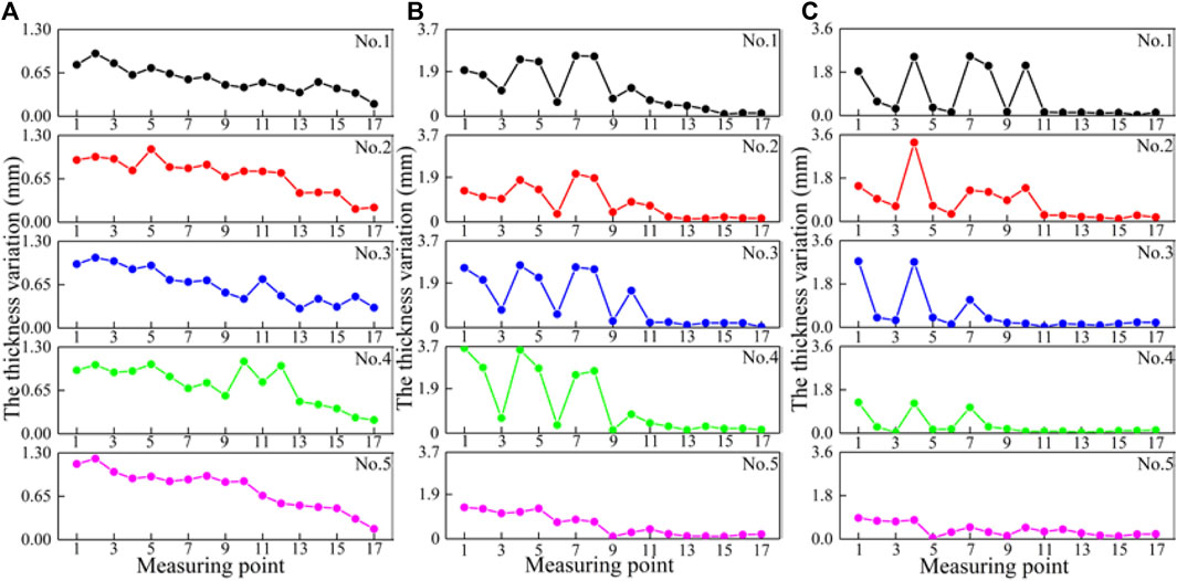
FIGURE 12. Thickness variation of the impeller at measuring points related with different particle diameters (A) 0.125–0.212 mm, (B) 0.212–0.425 mm, and (C) 0.425–0.710 mm.
Figure 12A shows that the thickness variation at the measuring point when the solid particle diameter is 0.212–0.425 mm. Along the axial direction of the impeller, the upper edge of the blade (the position of points 1, 2, 4, 5, 7, 8, 10, 11, and 12) is more worn. The blades of impeller 5 are worn lighter than the blades of the other four impellers. At points 12, 13, 14, 15, 16, and 17, the wear loss is almost the same and fluctuates about 0.243 mm.
Figure 12B shows the thickness variation at the position of the measuring point when the solid particle diameter is 0.425–0.710 mm. The degree of wear in different areas of the blade surface has a great difference. At points 11, 12, 13, 14, 15, 16, and 17, the wear loss is almost the same and fluctuates about 0.125 mm. The wear loss at different positions of the No. 5 impeller fluctuates about 0.382 mm. This situation is very different from other impellers.
For different mass concentrations, the most severe position of blade wear is the trailing edge. The reason is related to the fluidity and movement state of solid particles in high mass concentration. When the particle diameter is small, the particle flow is more fluid. When the particles enter the impeller channel, the axial velocity increases faster. Therefore, the impact of the blade is less, which causes little difference in wear at each measuring point. When the particle diameter is large, the fluidity of the particles becomes worse, and the interaction between the particles suppresses the movement of the particles. When the particles enter the impeller channel, the axial velocity increases slowly, so it will impact the pressure surface at the middle and trailing edge of the blade strongly, which will cause more serious wear in these positions. This result is consistent with the numerical simulation result of Liu (Ojala et al., 2016).
Influence of Impeller Material on Impeller Erosion Wear
This section analyzes the influence of impeller material on impeller erosion wear. The experiment was conducted under the material of impellers 16Mn, HT200, and Q235. The mass concentration of the solid is 30%, and the solid particle diameter is 0.125–0.212 mm.
As can be seen from Figure 13, the material with the largest thickness variation is Q235, followed by 16 Mn, and the smallest is HT200. Moreover, the variation values of blade thickness of Q235 and 16 Mn are similar but are quite different from those of HT200. The reason may be that Q235 and 16 Mn have similar mechanical properties. The hardness of HT200 is greater than that of the other two materials, so its loss of wear is less when compared to the other two materials. The result is consistent with that of Niko (Marshall, 2009).
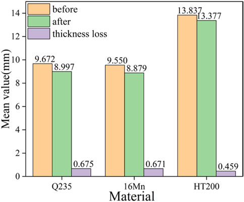
FIGURE 13. Mean thickness value of different material blades at measuring points.
Figures 14, 15 show the surface wear of impellers of different materials. The impellers made of 16 Mn and Q235 have similar wear shapes on the pressure surface. There are small erosion pits in the middle of the pressure surface and larger wear shapes at the end edge and lower end of the pressure surface, which may be because the crystal structures of the two materials are relatively similar. The wear performance of the impeller made of HT200 is slightly different, and because red paint is applied, it can be seen that the middle part of the pressure surface is obviously darker, and when the red paint is basically obliterated, it indicates that the middle part of the pressure surface is severely worn. This should be determined by the material structure. The roughness of the Q235 material surface is relatively large, which affects the flow characteristics of solid–liquid two-phase flow on the impeller surface.
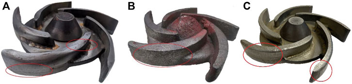
FIGURE 14. Blade wear under different materials. (A) 16 Mn, (B) HT200, and (C) Q235.
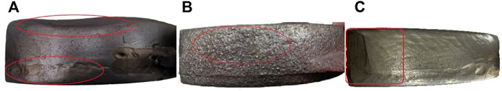
FIGURE 15. Pressure surface wear under different materials. (A) 16 Mn, (B) HT200, and (C) Q235.
Figure 16A shows the thickness variation at the measuring point when the material is 16 Mn. It can be found that from point 1 to point 14, the wear loss is larger, while from point 14 to point 17, the wear loss begins to decrease. Along the axial direction of the impeller, the position of points 1, 2, 4, 5, 7, 8, 10, 11, 12, and 14 are more worn. Figure 16B shows the thickness variation at the measuring point when the material is HT200. The amount of wear has fluctuated greatly; this is because the HT200 material brittleness is higher; therefore, when damaged by impact, there will be pieces that fall off.
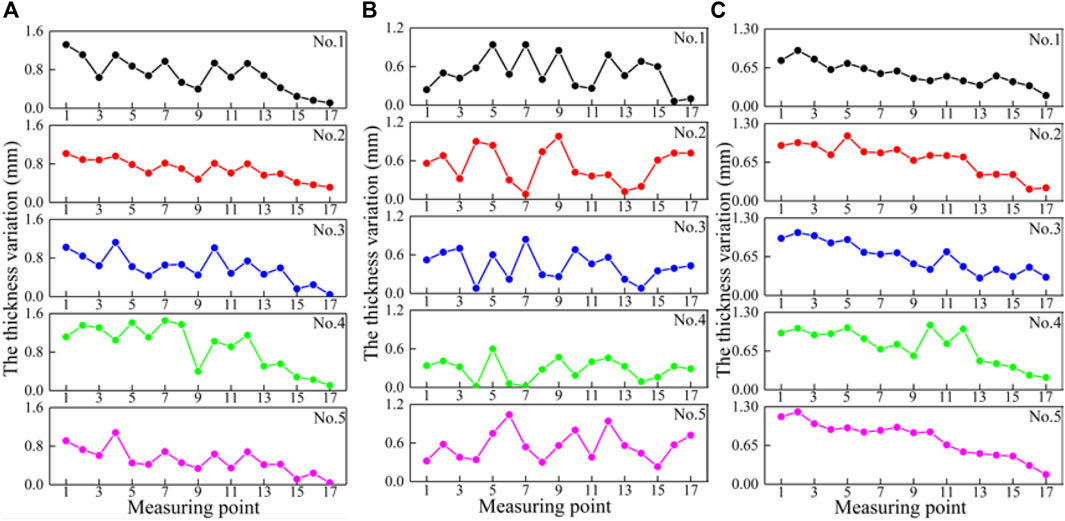
FIGURE 16. Thickness variation of the blade at measuring points related with different materials (A) 16 Mn, (B) HT200, and (C) Q235.
Erosion Mechanism Analysis
Figures 17, 18 show the wear morphology of the three kinds of materials of blade (Q235, 16 Mn, and HT200) under the same test conditions. From the pictures, it can be seen that the wear morphology of the three kinds of materials was different. Figure 17 shows the wear of the trailing edge of the blade. Figure 17A,B show that the wear morphology is corrugated. This is because the plasticity and toughness of Q235 and 16 Mn are relatively large, and the corrugated morphology will be generated when the mass concentration is large. Compared with Figure 17B, there is an impact pit in Figure 17A;the reason is that the matrix structure of Q235 is ferrite–pearlite. When the solid particles impact the blade surface, the ferrite with greater brittleness is more likely to fracture and break to form the pit. The matrix of 16Mn is also ferrite–pearlite, but due to the addition of alloying elements, it has a role in fine-grain strengthening, and it is not easy to produce erosion pits.
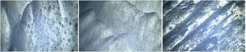
FIGURE 17. Surface micrographs of the trailing edge of the blade wear different material.
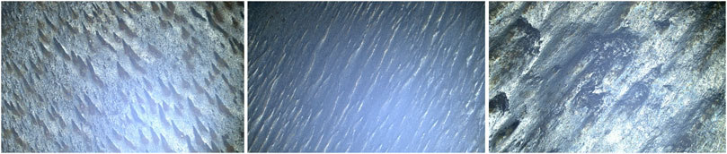
FIGURE 18. Surface micrographs of the head of the blade of different material after erosion wear.
Figure 18 shows the wear of the head of the blade. Figure 18A,B show an erosion pit at the position of the blade head. This is because at the blade head, the wear of the solid particles on the blade is impact wear. The impact pit is a groove mark in a certain direction. Since ferrite and pearlite structures are directionally distributed, directional plough marks are generated. Figure 17C, Figure 18C show a large area of erosion grooves and peeling off, which attribute to the fact that the matrix of HT200 is pearlite, its graphite content is large, and the distribution is a medium flake. The presence of flake graphite splits the continuity of the pearlite matrix, and the graphite tip will also cause stress concentration, so its mechanical properties are relatively poor. When solid particles impact the blade surface, erosion pits and brittle flaking will occur.
The presence of a large amount of graphite in gray cast iron improves its wear resistance. Moreover, the hardness of HT200 is much greater than that of Q235 and 16Mn. Therefore, the wear loss of HT200 is far less than that of the other two materials.
Conclusion
In this study, the erosion wear of centrifugal pump blades was studied by experiment and the following conclusions were obtained:
(1) The wear of solid particles on the blade is mainly concentrated in the middle and trailing edge of the blade. In the axial direction of the impeller, the wear on the top of the pressure surface is more serious.
(2) Under the conditions of the experiment, the increase of the mass concentration will aggravate the wear loss of the impeller. The change of particle size also has an important effect on wear.
(3) The matrix structure of carbon structural steel (Q235), gray cast iron (HT200), and low-alloy high-strength steel (16 Mn) determines their erosion wear characteristics. HT200 has high hardness and brittleness, and its erosion wear characteristics are mainly fractured and spalling. However, Q235 and 16 Mn have stronger plasticity and toughness, so their wear characteristics are mainly cutting erosion wear. Among them, the material with high hardness and a large amount of graphite has good erosion resistance. Under the same test conditions, the order of wear loss from large to small is Q235 > 16 Mn > HT200.
(4) In this study, the influence of three parameters on blade wear is studied. By comparing the thickness changes, it is found that the influence of particle size on blade wear is greater than that of the other two parameters (material and concentration).
Data Availability Statement
The raw data supporting the conclusions of this article will be made available by the authors, without undue reservation.
Author Contributions
Conceptualization: YW, ZZ, and HL; formal analysis: TH, WL, and CH; investigation: YW and TH; writing—original draft preparation: TH and WL; writing—review and editing, YW, TH, and WL; supervision: ZZ and HL. All authors have read and agreed to the published version of the manuscript.
Funding
Top-notch Talent Support Program of Zhejiang Province (2019R51002). The authors thanks for the financial support of National Natural Science foundation of China (Grant No. 51676174), the National Natural Science Foundation of China (Grant No. U1709209) and the Open Research Subject of Key Laboratory (Research Base) of szjj 2016-073.
Conflict of Interest
The authors declare that the research was conducted in the absence of any commercial or financial relationships that could be construed as a potential conflict of interest.
Publisher’s Note
All claims expressed in this article are solely those of the authors and do not necessarily represent those of their affiliated organizations, or those of the publisher, the editors, and the reviewers. Any product that may be evaluated in this article, or claim that may be made by its manufacturer, is not guaranteed or endorsed by the publisher.
References
Amaro, A. M., Loureiro, A. J. R., Neto, M. A., and Reis, P. N. B. (2020). Residual Impact Strength of Glass/epoxy Composite Laminates after Solid Particle Erosion. Compos. Struct. 238, 112026. doi:10.1016/j.compstruct.2020.112026
Arabnejad, H., Shirazi, S. A., McLaury, B. S., Subramani, H. J., and Rhyne, L. D. (2015). The Effect of Erodent Particle Hardness on the Erosion of Stainless Steel. Wear 332-333, 1098–1103. doi:10.1016/j.wear.2015.01.017
Aslfattahi, N., Samylingam, L., Abdelrazik, A. S., Arifutzzaman, A., and Saidur, R. (2020). MXene Based New Class of Silicone Oil Nanofluids for the Performance Improvement of Concentrated Photovoltaic Thermal Collector. Sol. Energy Mater. Sol. Cells 211, 110526. doi:10.1016/j.solmat.2020.110526
Azimian, M., and Bart, H.-J. (2015). Erosion Investigations by Means of a Centrifugal Accelerator Erosion Tester. Wear 328-329, 249–256. doi:10.1016/j.wear.2015.02.002
Bansal, A., Singh, J., and Singh, H. (2020). Erosion Behavior of Hydrophobic Polytetrafluoroethylene (PTFE) Coatings with Different Thicknesses. Wear 456-457, 456203340–456203457. doi:10.1016/j.wear.2020.203340
Bozzini, B., Ricotti, M. E., Boniardi, M., and Mele, C. (2003). Evaluation of Erosion-Corrosion in Multiphase Flow via CFD and Experimental Analysis. Wear 255, 237–245. doi:10.1016/S0043-1648(03)00181-9
Das, L., Rubbi, F., Habib, K., Aslfattahi, N., Saidur, R., Baran Saha, B., et al. (2021). State-of-the-art Ionic Liquid & Ionanofluids Incorporated with Advanced Nanomaterials for Solar Energy Applications. J. Mol. Liq. 336, 116563. doi:10.1016/j.molliq.2021.116563
Feng, C., Chen, D., Xu, M., Shen, C., Yang, L., and Jiang, J. (2020). Study of Solid Particle Erosion Wear Resistance of WC-Co Cemented Carbide. J Fail. Anal. Preven. 20, 543–554. doi:10.1007/s11668-020-00861-6
Grant, G., and Tabakoff, W. (1975). Erosion Prediction in Turbomachinery Resulting from Environmental Solid Particles. J. Aircr. 12, 471–478. doi:10.2514/3.59826
Guangjie, P., Zhengwei, W., Yexiang, X., and Yongyao, L. (2013). Abrasion Predictions for Francis Turbines Based on Liquid-Solid Two-phase Fluid Simulations. Eng. Fail. Anal. 33, 327–335. doi:10.1016/j.engfailanal.2013.06.002
Islam, M. A., and Farhat, Z. N. (2014). Effect of Impact Angle and Velocity on Erosion of API X42 Pipeline Steel under High Abrasive Feed Rate. Wear 311, 180–190. doi:10.1016/j.wear.2014.01.005
Iwai, Y., and Nambu, K. (1997). Slurry Wear Properties of Pump Lining Materials. Wear 210, 211–219. doi:10.1016/S0043-1648(97)00055-0
Kadirgama, K., Samylingam, L., Aslfattahi, N., Mahendran, S., Ramasamy, D., and Saidur, R. (2021). Experimental Investigation on the Optical and Stability of Aqueous Ethylene Glycol/Mxene as a Promising Nanofluid for Solar Energy Harvesting. IOP Conf. Ser. Mat. Sci. Eng. 1062 (1), 012022. (9pp). doi:10.1088/1757-899X/1062/1/012022
Lai, F., Wang, Y., Ei-Shahat, S. A., Li, G., and Zhu, X. (2019). Numerical Study of Solid Particle Erosion in a Centrifugal Pump for Liquid-Solid Flow. J. Fluids Eng. 141, 121302. doi:10.1115/1.4043580
Liu, J. H., and Zhu, M. Y. (2011). Simulation Study on Attrition to Centrifugal Sewerage Pump. Kem 474-476, 1107–1110. doi:10.4028/www.scientific.net/kem.474-476.1107
Liu, J., Xu, H., Qi, L., and Li, H. (2004). Study on Erosive Wear and Novel Wear-Resistant Materials for Centrifugal Slurry Pumps. Proceedings of the ASME 2004 Heat Transfer/Fluids Engineering Summer Conference 3, Charlotte, North Carolina, USA: ASME, 101–104. doi:10.1115/HT-FED2004-56248
Marshall, J. S. (2009). Discrete-element Modeling of Particulate Aerosol Flows. J. Comput. Phys. 228 (5), 1541–1561. doi:10.1016/j.jcp.2008.10.035
Medvedovski, E., and Antonov, M. (2020). Erosion Studies of the Iron Boride Coatings for Protection of Tubing Components in Oil Production, Mineral Processing and Engineering Applications. Wear 452-453, 452203277–452203453. doi:10.1016/j.wear.2020.203277
Ng, B. H., Ding, Y., and Ghadiri, M. (2008). Assessment of the Kinetic-Frictional Model for Dense Granular Flow. Particuology 6 (1), 50–58. doi:10.1016/j.cpart.2007.10.002
Nguyen, Q. B., Lim, C. Y. H., Nguyen, V. B., Wan, Y. M., Nai, B., Zhang, Y. W., et al. (2014). Slurry Erosion Characteristics and Erosion Mechanisms of Stainless Steel. Tribol. Int. 79, 1–7. doi:10.1016/j.triboint.2014.05.014
Ojala, N., Valtonen, K., Antikainen, A., Kemppainen, A., Minkkinen, J., Oja, O., et al. (2016). Wear Performance of Quenched Wear Resistant Steels in Abrasive Slurry Erosion. Wear 354-355, 21–31. doi:10.1016/j.wear.2016.02.019
Oka, Y. I., Okamura, K., and Yoshida, T. (2005). Practical Estimation of Erosion Damage Caused by Solid Particle Impact. Wear 259, 95–101. doi:10.1016/j.wear.2005.01.039
Ovchinnikov, N. P., Vikulov, M. A., and Portnyagina, V. V. (2019). Calculation of the Maximum Metal Consumption Loss for a Single-Stage Centrifugal Pump Impeller. IOP Conf. Ser. Earth Environ. Sci. 229, 012012. doi:10.1088/1755-1315/229/1/012012
Prasanna, N. D., Siddaraju, C., Shetty, G., Ramesh, M. R., and Reddy, M. (2018). Studies on the Role of HVOF Coatings to Combat Erosion in Turbine Alloys. Mater. Today Proc. 5, 3130–3136. doi:10.1016/j.matpr.2018.01.119
Rubbi, F., Das, L., Habib, K., Aslfattahi, N., Saidur, R., and Alam, S. U. (2021). A Comprehensive Review on Advances of Oil-Based Nanofluids for Concentrating Solar Thermal Collector Application. J. Mol. Liq. 338 (4), 116771. doi:10.1016/j.molliq.2021.116771
Samylingam, L., Aslfattahi, N., Saidur, R., Yahya, S. M., Afzal, A., Arifutzzaman, A., et al. (2020). Thermal and Energy Performance Improvement of Hybrid PV/T System by Using Olein Palm Oil with MXene as a New Class of Heat Transfer Fluid. Sol. Energy Mater. Sol. Cells 218 (C), 110754. doi:10.1016/j.solmat.2020.110754
Shah, S. N., and Jain, S. (2008). Coiled Tubing Erosion during Hydraulic Fracturing Slurry Flow. Wear 264, 279–290. doi:10.1016/j.wear.2007.03.016
Shen, Z. J., Li, R. N., Han, W., Zhao, W. G., and Wang, X. H. (2016). The Research on Particle Trajectory of Solid-Liquid Two-phase Flow and Erosion Predicting in Screw Centrifugal Pump. IOP Conf. Ser. Mat. Sci. Eng. 129, 012052–012059. doi:10.1088/1757-899X/129/1/012052
Singh, J., Kumar, S., and Mohapatra, S. K. (2019). Tribological Performance of Yttrium (III) and Zirconium (IV) Ceramics Reinforced WC-10Co4Cr Cermet Powder HVOF Thermally Sprayed on X2CrNiMo-17-12-2 Steel. Ceram. Int. 45, 23126–23142. doi:10.1016/j.ceramint.2019.08.007
Tarodiya, R., and Gandhi, B. K. (2019). Experimental Investigation of Centrifugal Slurry Pump Casing Wear Handling Solid-Liquid Mixtures[J]. Wear 434, 202972. doi:10.1016/j.wear.2019.202972
Walker, C. I., and Bodkin, G. C. (2000). Empirical Wear Relationships for Centrifugal Slurry Pumps. Wear 242, 140–146. doi:10.1016/s0043-1648(00)00413-0
Walker, C. I., and Robbie, P. (2013). Comparison of Some Laboratory Wear Tests and Field Wear in Slurry Pumps. Wear 302, 1026–1034. doi:10.1016/j.wear.2012.11.053
Xing, D., Hai-lu, Z., and Xin-yong, W. (2009). Finite Element Analysis of Wear for Centrifugal Slurry Pump. Procedia Earth Planet. Sci. 1, 1532–1538. doi:10.1016/j.proeps.2009.09.236
Keywords: solid–liquid two-phase fluid, numerical simulation, particle diameters, mass concentration, erosion wear, morphology characterization
Citation: Wang Y, Li W, He T, Liu H, Han C and Zhu Z (2022) Experimental Study on the Influence of Particle Diameter, Mass Concentration, and Impeller Material on the Wear Performance of Solid–Liquid Two-Phase Centrifugal Pump Blade. Front. Energy Res. 10:893385. doi: 10.3389/fenrg.2022.893385
Received: 10 March 2022; Accepted: 26 April 2022;
Published: 21 June 2022.
Edited by:
Kan Kan, College of Energy and Electrical Engineering, ChinaReviewed by:
Weihua Cai, Northeast Electric Power University, ChinaKumaran Kadirgama, Universiti Malaysia Pahang, Malaysia
Copyright © 2022 Wang, Li, He, Liu, Han and Zhu. This is an open-access article distributed under the terms of the Creative Commons Attribution License (CC BY). The use, distribution or reproduction in other forums is permitted, provided the original author(s) and the copyright owner(s) are credited and that the original publication in this journal is cited, in accordance with accepted academic practice. No use, distribution or reproduction is permitted which does not comply with these terms.
*Correspondence: Zucao Zhu, emh1enVjaGFvQHpzdHUuZWR1LmNu