 Yuchen Hao
 Yue Li
 Musen Lin
 Bin Wu
- Key Laboratory of Advanced Reactor Engineering and Safety of Ministry of Education, Collaborative Innovation Center of Advanced Nuclear Energy Technology, Institute of Nuclear and New Energy Technology, Tsinghua University, Beijing, China
Reliable transportation of fuel elements is vital for High Temperature Reactor (HTR) power plant. Therefore, the safety performance of the containment boundary in HTR-PM600 fresh fuel transport package under impact loading should be assessed. Specifically, factors such as the structural integrity, bolt safety, and sealing performance of the flange are considered. However, it is not convenient to assess the sealing performance using the helium leakage test without a prototypical experiment. Therefore, to accurately assess the safety performance in the design stage, we propose a detection technique combing with the finite element method to measure the leak channel in the flange for HTR-PM600 transport package. The results show that the boundary containment has no failure, and there is no complete leak channel in the flange of HTR-PM600 package. Hence, this package has a great safety performance under impact loading. This work also provides references for design of fresh fuel transport packages in pebble-bed reactors.
Introduction
Nuclear power, a form of green and clean energy, has been widely developed as an effective solution for reducing carbon emissions in terms of electricity supply (Dong et al., 2018). The high temperature reactor (HTR) is a Generation IV advanced nuclear reactors known for its safety and reliability. The pebble-bed reactor is considered as one of the primary possibilities for realising HTR systems. China has successfully established the 10 MWth prototype pebble bed reactor (HTR-10) and high temperature reactor-pebble bed modules (HTR-PM). For further development, the project of a 660 MWe Nuclear Power Plant (NPP) HTR-PM600 is proposed.
The reliable transportation of SFEs is crucial for the HTR power plants. Therefore INET (institute of nuclear and new energy technology) is developing the HTR-PM600 transport package system. The spherical elements are stored in the transport package, and then transported to nuclear power plants (IAEA, 2006). Considering unexpected traffic accidents on the road, transport packages are required to meet safety regulations. The IAEA safety requirement SSR-6 lists the test methods for all types of packages under normal and accident conditions (IAEA, 2018). Two different drop tests under the accident condition are of major concern, including a 9 m drop to an unyielding surface and a 1 m drop to a bar rigidly installed on an unyielding surface. The relevant tests have been extensively studied. Kim et al. (2010) presented a simulation and experiment on a KN-18 spent nuclear fuel transport cask in 9 m drop test and 1 m puncture test. Jakšić and Nilsson (2009) demonstrated the structural performance of the CASTOR AVR cask in 1 m puncture test. Under such extreme conditions, the safety performance of containment boundary for nuclear fuel has become a focus of research.
The total containment boundary system for nuclear fuel consists of a containment vessel, bolts, lids, cover plates, and other closure devices. Researchers have explored criteria such as the containment evaluation criteria in NUREG-2216 (U.S. Nuclear Regulatory Commission, 2020a) and criteria for closure bolts for shipping casks in NUREG/CR-6007 (US Nuclear Regulatory Commission, 1992).
The sealing flange may be a weak link in the containment boundary. The leakage standard for detecting the pressure variation in the spent nuclear fuel (SNF) cask is presented in Regulatory Guide 7.4 Revision 2 (U.S. Nuclear Regulatory Commission, 2020b), and the test procedures are specified in ANSI N14.5 (ANSI, 1997). Saito et al. (2014) investigated the sealing performance on the MSF-type cask for PWR spent fuel using helium leakage tests. Wang (2009) studied the sealing performance of containment of SNF cask based on theoretical and empirical methods, and the reference air and helium leakage rates were investigated based on the case of the NAC-STC cask. However, it is not convenient to assess the sealing performance using the helium leakage test without a prototypical experiment. The more important is that the sealing performance should be initially assessed to improve the robustness of project before the manufacture and further actual test. Therefore, we propose a detection technique combing with the finite element method to measure the leak channel in the flange for HTR-PM600 transport package. That is indeed needed for the industry of nuclear fuel transport.
In this study, a containment integrity and sealing assessment was conducted on the HTR-PM600 fresh fuel transport package under impact loading. The remainder of this paper is organised as follows. The structure, material, and FE (finite element) modelling of HTR-PM600 fresh fuel transport package are presented in Structure and FE Methodology. The containment integrity and sealing assessment method, are presented in Containment Integrity and Sealing Assessment Method. The numerical simulation is conducted using the FE code, and the safety performances of HTR-PM600 package are reported in Result and Discussion. Finally, the conclusions are presented in Conclusion.
Structure and FE Methodology
Structure Description
In recent decades, as HTR systems have been improving, the structure of fresh fuel transport packages in pebble-bed reactors has developed to meet the requirements in terms of safety and economy. Figure 1 shows the main components of the HTR-PM600 fresh fuel transport package—the transport container and storage canisters.
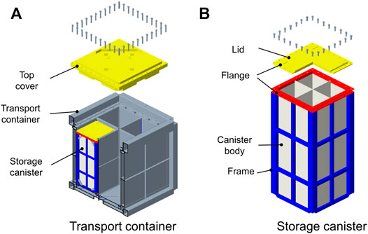
FIGURE 1. Illustration of HTR-PM600 package. (A) transport container (B) storage canister.
Four canisters are housed in a transport container. The transport container, an approximate cubic vessel, is designed for road transport. The container can protect the canister and inner fuel elements in drop tests, puncture tests, fire tests, and other extreme conditions. The top cover in the transport container is connected to the transport container body with 40-M36 bolts.
The storage canister is thin-walled but is capable of storing numerous spherical nuclear fuel elements. The canister consists of a lid, flange, canister body, and frame. The canister body has a rectangular cross-section and has opening at the top. The lid is connected to the canister body with 28-M20 bolts. In this system, the lid flange, bolts, and canister body constitute the containment boundary to prevent leakage of the TRISO-coated fuel particles. From this perspective, the storage canister plays an important role in the protection and containment of nuclear fuel.
The transport container and storage canister are manufactured mainly using stainless steel 304. In addition, polyurethane foam is used in the container for thermal insulation and energy absorption. The bolt is fabricated using austenitic stainless steel A2-80.
The total weight of the transport container with the four housing canisters is approximately 11 tons. The external package size is approximately 2,400 mm × 2,400 mm, with a height of 2,400 mm.
Material Properties
The mechanical properties of the metallic materials used for the HTR-PM600 transport package are summarised in Table 1. For stainless steel 304, the mechanical properties are referring to the ASME standard (American Society of Mechanical Engineers, 2015), and the constitutive modelling is governed by a piecewise linear plasticity model that accounts for failure. For the bolt, high-strength austenitic stainless steel A2-80 is used following ISO 3506-1 (International Organization for Standardization, 2020). The polyurethane foam absorbs the impact kinetic energy in a drop accident through its own compression. The material parameters were recommended by Nichols (Nichols et al., 2001), and the crushing strength property of classical polyurethane foam (product code for FR-3700) is 1.1 MPa for 10% strain (General Plastics Manufacturing Company, 1999).
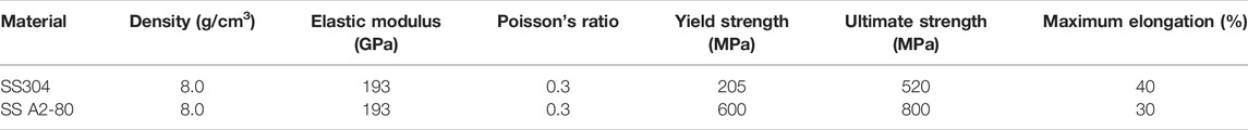
TABLE 1. Mechanical properties of metallic materials.
Finite Element Modelling
Drop tests are commonly regarded as the most reliable method to ensure the safety and dynamic response of the transport cask under accident events. However, the actual test is usually expensive and time-consuming. With the development of computer technology, the application of explicit dynamic code, such as LS-DYNA to simulate the cask drop, has become popular and has been validated by many researchers (Kim et al., 2010b; Wu et al., 2012; Sichani et al., 2019). LS-DYNA is a commercial FE program that offers highly nonlinear and transient analysis (Livermore Software Technology Corporation, 2019). In this study, the FE model (Figure 2) was established using the LS-PrePost pre-processing software package. The model represents the entire transport container and canister. The element type for all thin-walled components was the shell element. For the thin-walled canister, the thickness of the thin wall is much smaller than two other characteristic sizes, thus, in comparison with the solid elements, the shell element is recommended to obtain more accurate results with fewer elements to reflect the bending. The number of integration points through the thickness were set to five for sufficient accuracy. The foam models were analysed using solid elements. For the bolt model, it is efficient to use beam connections with the preloads because the beam model requires less time to create and solve than the other models do, especially for a large number of bolts. The nut and bolt head were modelled using rigid beams to connect with the adjacent nodes, while the bolt shank was modelled with the bolt beam. The sliding behaviour and friction effect of the upper flange and lower flange were considered. The additional mass method (Liu, 2015) was used to simulate the behaviours of 4.5 tons of nuclear fuel during the process of drop, thus the additional mass of fuel is uniformly distributed to bottom wall of containment boundary for bottom-down drop case, to top and side wall for top-corner drop case, and to side wall for side puncture case. The entire model had 498,430 elements and 492,260 nodes. The mesh was designed for the accurate prediction for the important structural behaviours.
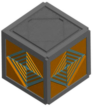
FIGURE 2. FE model of cask.
Dynamic relaxation was used before performing the transient dynamic analysis. For the nth time increment, the equation for developing the dynamic relaxation method for structural analysis is (Belytschko et al., 1985)
where M is the mass matrix, C is the damping matrix, t is time, and q is the vector of dependent discrete variables. This equation is solved using the central difference method:
where h is a fixed time increment.
Therefore, to apply a preload to the bolts, the load curve (axial force versus time) is input by the user, and the load in the bolt is set equal to the value given in the curve until the end of the load. Finally, dynamic relaxation is completed when the load, contact force, and stress are equalised. Some accidental drop tests are required by IAEA SSR-6. In this study, a 9 m drop to an unyielding surface and a 1 m drop to a steel bar were investigated. Three typical drop scenarios were considered with different orientations including bottom-down drop, top-corner drop, and side puncture, as shown in Figure 3. To save calculation resources, equivalent initial velocity is 13.3 m/s for bottom-down and top-corner drop, 4.2 m/s for 1 m side puncture.
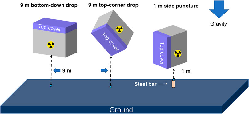
FIGURE 3. Illustrations of the three drop scenarios.
Containment Integrity and Sealing Assessment Method
Outlines of Containment Boundary
The containment boundary should maintain its integrity under accident conditions. The containment boundary system for the HTR-PM600 fresh fuel transport package, is shown in Figure 4, where the structural integrity, bolt safety, and sealing performance should be assessed.
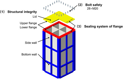
FIGURE 4. Assessment criteria for containment boundary.
Structural Integrity
NUREG-2216 (U.S. Nuclear Regulatory Commission, 2020a) prescribes containment evaluation criteria for the Type AF fissile package. The structural assessment criteria stipulate that there must be no loss or dispersal of radioactive material under normal conditions and that the radioactive material must be confined to a known geometry to remain sub-critical under both normal and accident conditions.
For the HTR-PM600 transport package, the structural integrity assessment focused on three essential components in the storage canister, that is lid, sidewall, and bottom wall, which directly contain the nuclear fuel element. The effective plastic strain is considered to be crucial to reflect the mechanical behaviours of the aforementioned components. Leakage of radioactive material will occur if the value of the effective plastic strain exceeds the maximum elongation of the material; the package will not satisfy the acceptance criteria in this case.
Bolt Safety
The bolt closure, as a part of the integrated structure, provides leak-proofing in the containment system to prevent leakage of radioactive material. However, it is also a weak link in nuclear fuel containers under accident conditions. Therefore, in this study, the safety of 4 × 28 bolts installed on the canister flange should be validated.
The safe performance of bolt closure depends mainly on the number and strength of the bolts. NUREG/CR-6007 (US Nuclear Regulatory Commission, 1992) provides guidance and criteria for closure bolts for shipping casks. For the bolt analysis shown in Figure 5, the axial tensile force, shear force, bending moment, and torsional moment are considered. The axial tensile and transverse shear bolt forces are the primary forces. Although the bending moment and torsional moment are not dominant factors, they are also considered to improve the calculation accuracy.
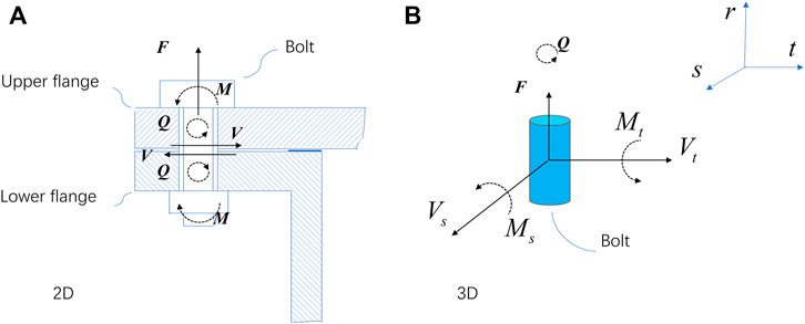
FIGURE 5. Forces and moments in a bolt in 2D and 3D: F is the axial resultant force, Ms is the resultant bending moment around the S axis, Mt is the resultant bending moment around the T axis, Q is the resultant torsional moment, Vs is the shear force along S, and Vt is the shear force along T. (A) 2D (B) 3D.
Based on a study on the bolt failure criteria provided by (Grelli, 2017), axial stress
where A is the sectional area, Z is the section modulus, and d is the diameter of the bolt shank.
The stress analysis of bolts is based on elastic range. According to the requirement issued by NUREG/CR-6007 (US Nuclear Regulatory Commission, 1992), the stress should not exceed the yield strength. Therefore, the final stress limitation in Eqs 8, 9 and the bolt coefficient in Eq. 10 for bolt are calculated as follows:
where
Sealing Performance of Flange
The flange is also a major part of the containment boundary. The flange deforms under impact loading, in this case the inner TRISO-coated particles (d = 0.92 mm) have the possibility to leak through the channel in the flange, as indicated by the marked points in Figure 6. The sets of marked points can be divided into two categories: incomplete leak channel (regions 1,2, and 3 in Figure 6.) and complete leak channel (region 4 in Figure 6.). The particles can escape only when the complete leak channel is formed in the flange.
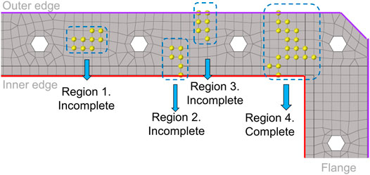
FIGURE 6. Illustration of the leak channel.
The acceptance of sealing criteria is thus determined, and an accurate detection technique is required to describe the sealing performance of the flange. Figure 7 shows the main flow of the proposed detection technique.
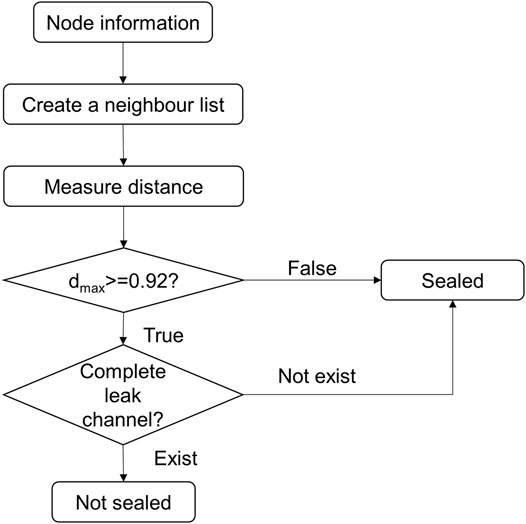
FIGURE 7. Flow chart of the detection technique.
Step 1, Create a neighbour list: The neighbour list contains information about node positions. For example (Figure 8A), nodes B, C, and D in the lower flange are closest to node A in the upper flange; thus, the node information about the number and corresponding coordinates are recorded in the neighbour list.
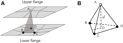
FIGURE 8. Schematic of the detection technology. (A) neighboring nodes (B) constructed tetrahedron.
Step 2, Measure the distance: Figure 8B shows the tetrahedron constructed by the four nodes mentioned in Step 1. Distance d between node A of the upper flange and the face of the lower flange was calculated by the height of the tetrahedron. For thousands of nodes in the upper flange, the distance from the nodes to the lower flange was recorded in a set
If the
Step 3, Leak channel detection: Figure 9 illustrates the detection of the flange’s leak channel using depth-first search (DFS) algorithm. DFS is a typical algorithm for traversing or searching graph structures in the field of graph theory (Photphanloet and Lipikorn, 2020). DFS uses a vertex as a starting point to visit neighbouring vertices. One of the adjacent vertexes that has not been visited is selected as the new starting point. The DFS algorithm backtracks until the selected point has no unvisited adjacent vertices. In this study, the vertices are the nodes with an opening size greater than 0.92 mm, as calculated in Step 2. As shown in Figure 9, the orange nodes are on the inner side of the flange, whereas the destination is on the outer side. The DFS algorithm starts at the orange node and explores as far as possible along each branch before backtracking; it stops when arriving at the red nodes or when all nodes are traversed. If a complete leak channel exists, the flange loses its sealing performance and the containment boundary is destroyed.
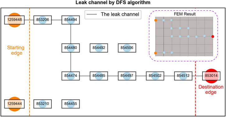
FIGURE 9. Leak path detection.
Protection of Containment Boundary
The transport container plays a key role in the protection of the containment boundary, which is used for absorbing kinetic energy under extreme accident conditions. The more energy the transport container absorbs, the safer are the inner storage canisters. The primary goal of this research was to ensure the safety of the containment boundary; Localised failure or damage is acceptable for transport container. Therefore, the only situation that should be focused on was the failure of the transport container bolts, which may result in separation of the storage canister from the transport container, in turn, inducing further damage. In this study, our primary concern was the number of bolts that failed in the transport container.
Result and Discussion
This section presents the test results of FE drop and puncture analyses conducted on the HTR-PM600 transport package using the explicit dynamic code LS-DYNA. In addition, the containment integrity and sealing performance of HTR-PM600 transport package is assessed.
Energy Balance
Figures 10A–C illustrate the energy versus time-history curves of the three cases used in the numerical analysis. Each includes kinetic energy, internal energy, total energy, hourglass energy, and sliding energy. Owing to the initial drop height, the gravitational potential energy continues to be converted into total energy. In addition, the total energy remained stable from beginning to end. As the peak hourglass energy was always less than 4.2% of the total energy, it could be easily conducted that the control of hourglass energy is successful. The negative sliding energy was also investigated. Although the negative sliding energy cannot be avoided in a complex contacting system, only a small percentage of the total energy is acceptable. In addition, the smooth energy balance curves demonstrate no numerical instability. As such, all the numerical simulations can be said to be accurately performed.
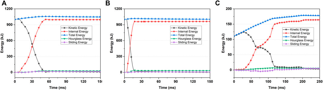
FIGURE 10. Energy balance curves of (A) 9-m bottom-down drop case (B) 9-m top-corner drop case (C) 1-m side puncture case.
Structural Integrity
Figures 11A–C illustrate the final effective plastic strain contours of the lid, sidewall, and bottom wall of the containment boundary. The bottom-down drop is a typical drop scenario. The maximum effective plastic strain at the bottom wall of the canister is approximately 11.57%. The top-corner drop is another representative drop scenario. The point of the corner fitting first contacts the ground at the initial stage, and the contact area begins to increase so that the transport container buckles to absorb the kinetic energy of the entire package to protect the inner storage canister. As we can see, the containment boundary has little plastic deformation under top-corner drop case that the transport container demonstrates the strong protection. In addition, the maximum local effective plastic strain in the 1-m side puncture case is approximately 15.63%, located in the side wall of containment boundary. The maximum effective plastic strains in the three cases are all lower than the 40%, thus our transport has great package structural integrity in such extreme accidents.
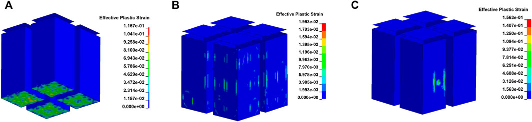
FIGURE 11. Effective plastic strain contours of the lids, sidewalls, and bottom walls of canister (A) under 9-m bottom-down drop (B) 9-m top-corner drop (C) 1 m side puncture.
Bolt Safety
The bolt safety coefficient experienced in the three cases are shown in Figures 12A–C. Based on the failure criteria given in (10), no failure occurred in the bolt of the containment boundary. It is easy to find that the bolt has the biggest bolt coefficient 0.92 under the top-corner drop case located at the corner of the canister. That is because flange has the deformation when the canister contacts the container under this case. The figure also shows the axial and shear stress curves of the bolt with the maximum bolt coefficient.
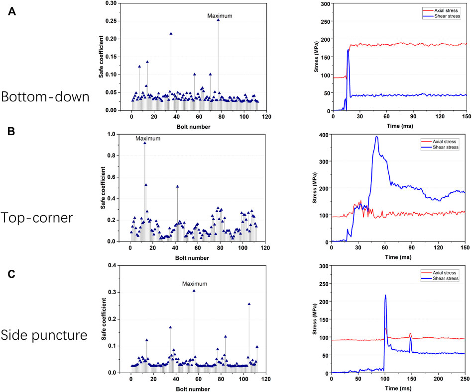
FIGURE 12. Bolt safe coefficient and stress of (A) bottom-down drop test (B) top-corner drop test (C) side puncture test.
Sealing Performance of Flange
A small gap was observed between the upper and lower flange due to the impact loading. The bottom-down and top-corner drop cases show that the maximum distance is 0.11 and 0.23 mm, respectively, much less than the outer diameter of the TRISO-coated particles. That is in compliance with the requirement.
As for side puncture, the maximum distance between the flange is 0.97 mm, which is larger than the outer diameter of the particles. To further evaluate the sealing performance of the flange, the leak channel detection technique mentioned in Containment Integrity and Sealing Assessment Method was used. Figure 13 shows the two regions and their leaking channel. As we can see, no complete leak channel exists; thus, the flange system still maintains the sealing performance under side puncture conditions. Compared with the node information abstracted from the FEM result, the results show that the detection technique can accurately evaluate the sealing performance of flanges.
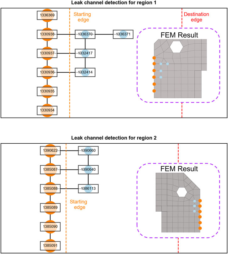
FIGURE 13. Leak-channel detection for region 1 and 2.
Automatic Assessment Technology
To improve the efficiency of evaluation, the code is developed using the automation technology to conduct on containment integrity and sealing assessment for HTR-PM600 fresh fuel transport package. Table 2 shows the comprehensive assessment result obtained using the code in a very short time.
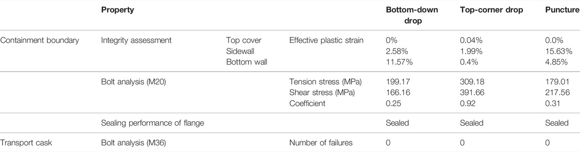
TABLE 2. Automatic quick assessment output for three drop cases based on our code.
Conclusion
This work studies on the containment integrity and sealing performance of the flange in HTR-PM600 fresh fuel transport package under the drop and puncture loading based on the dynamic finite element method. To improve the robustness of project and overcome the inconvenient helium leakage test before the actual test, a detection technique combing with the finite element method is proposed to measure the leak channel in the flange. The result clearly showed that the boundary containment has no failure and no complete leak channel exists in flange of HTR-PM600 package. This method can also be applied to other similar transport packages.
Data Availability Statement
The original contributions presented in the study are included in the article/Supplementary Material, further inquiries can be directed to the corresponding author.
Author Contributions
YL and JW contributed to the conception of the study; YH performed the numerical simulation, the data analyses and wrote the manuscript; ML contributed significantly to analysis and manuscript preparation; BW, TM, HW, and BL helped perform the analysis with constructive discussions.
Funding
This work has been supported by the National S&T Major Project (Grant No. ZX069) provided by the National Energy Bureau of China, and Modular HTGR Super-critical Power Generation Technology collaborative project between CNNC and Tsinghua University (Project No. ZHJTJZYFGWD2020).
Conflict of Interest
The authors declare that the research was conducted in the absence of any commercial or financial relationships that could be construed as a potential conflict of interest.
Publisher’s Note
All claims expressed in this article are solely those of the authors and do not necessarily represent those of their affiliated organizations, or those of the publisher, the editors and the reviewers. Any product that may be evaluated in this article, or claim that may be made by its manufacturer, is not guaranteed or endorsed by the publisher.
References
American Society of Mechanical Engineers (ASME) (2015). ASME BPVC Section II Part D Properties (Customary). New York, NY: ASME.
ANSI (1997). N14.5: Leakage Tests on Packages for Shipment. New York, NY: American National Standards Institute, Institute for Nuclear Materials Management.
Belytschko, T., Hughes, T. J. R., and Burgers, P. (1985). Computational Methods for Transient Analysis. J. Appl. Mech. 52 (4), 984. doi:10.1115/1.3169187
Dong, F., Yu, B., Hadachin, T., Dai, Y., Wang, Y., Zhang, S., et al. (2018). Drivers of Carbon Emission Intensity Change in China. Resour. Conservation Recycl. 129, 187–201. doi:10.1016/j.resconrec.2017.10.035
Grelli, E. (2017). Failure of Bolted Connections in Crash Test Simulations. Master’s thesis. Milano: Politecnico Di Milano.
General Plastics Manufacturing Company (1999). LAST-A-FOAM FR-3700 for Crash&Fire Protection of Nuclear Material Shipping Containers. TACOMA, WA: General Plastics Manufacturing Company.
IAEA (2018). No. SSR-6 (Rev. 1): Regulations for the Safe Transport of Radioactive Material 2018 Edition. Vienna: IAEA.
International Organization for Standardization (ISO) (2020). ISO 3506-1:2020: Fasteners — Mechanical Properties of Corrosion-Resistant Stainless Steel Fasteners — Part 1: Bolts, Screws and Studs with Specified Grades and Property Classes. Poland: Polski Komitet Normalizacyjny.
Jakšić, N., and Nilsson, K.-F. (2009). Finite Element Modelling of the One Meter Drop Test on a Steel Bar for the CASTOR Cask. Nucl. Eng. Des. 239, 201–213. doi:10.1016/j.nucengdes.2008.10.010
Kim, K.-S., Chung, S.-H., Kim, J.-S., Choi, K.-S., and Yun, H.-D. (2010). Demonstration of Structural Performance of IP-2 Packages by Advanced Analytical Simulation and Full-Scale Drop Test. Nucl. Eng. Des. 240, 639–655. doi:10.1016/j.nucengdes.2009.11.035
Kim, K.-S., Kim, J.-S., Choi, K.-S., Shin, T.-M., and Yun, H.-D. (2010). Dynamic Impact Characteristics of KN-18 SNF Transport Cask - Part 1: An Advanced Numerical Simulation and Validation Technique. Ann. Nucl. Energy 37, 546–559. doi:10.1016/j.anucene.2009.12.023
Liu, X. (2015). The Theoretical and Computational Analysis for the Drop Events of HTR-PM Spent Fuel Storage Canister. Master’s thesis. Beijing: Tsinghua University.
Livermore Software Technology Corporation (LSTC) (2019). LS-DYNA Keyword User’s Manual: Volume II Material Models R11. California: LSTC.
Nichols, J. C., Cohen, M. E., and Johnson, R. A. (2001). “Benchmarking of Ls-Dyna for Use with Impact Limiters,” in Waste Management Conference (Tucson, AZ: Waste Management Conference).
Photphanloet, C., and Lipikorn, R. (2020). PM10 Concentration Forecast Using Modified Depth-First Search and Supervised Learning Neural Network. Sci. Total Environ. 727, 138507. doi:10.1016/j.scitotenv.2020.138507
Saito, Y., Kishimoto, J., Matsuoka, T., Tamaki, H., and Kitada, A. (2014). Containment Integrity Evaluation of MSF-type Cask for Interim Storage and Transport of PWR Spent Fuel. Int. J. Press. Vessels Pip. 117-118, 33–41. doi:10.1016/j.ijpvp.2013.10.007
Sichani, M. E., Hanifehzadeh, M., Padgett, J. E., and Gencturk, B. (2019). Probabilistic Analysis of Vertical Concrete Dry Casks Subjected to Tip-Over and Aging Effects. Nucl. Eng. Des. 343, 232–247. doi:10.1016/j.nucengdes.2018.12.003
U.S. Nuclear Regulatory Commission (2020a). NUREG-2216: Standard Review Plan for Transportation Packages for Spent Fuel and Radioactive Material. Washington, DC: U.S. Nuclear Regulatory Commission.
U.S. Nuclear Regulatory Commission (1992). NUREG/CR-6007: Stress Analysis of Closure Bolts for Shipping Casks. Washington, DC: U.S. Nuclear Regulatory Commission.
U.S. Nuclear Regulatory Commission (2020b). RG 7.4 Revision 2: Leakage Tests on Packages for Shipment of Radioactive Material. Washington, DC: U.S. Nuclear Regulatory Commission.
Wang, Q. (2009). Research on Seal Issue of Containment of Spent Fuel Transport/Storage Cask (Beijing: Tsinghua University). Master’s thesis.
Keywords: HTR-PM600, fuel elements, fresh fuel transport package, finite element method, assessment method
Citation: Hao Y, Li Y, Lin M, Wu B, Ma T, Wang H, Liu B and Wang J (2022) Containment Integrity and Sealing Assessment for HTR-PM600 Fresh Fuel Transport Package Under Impact Loading. Front. Energy Res. 10:914090. doi: 10.3389/fenrg.2022.914090
Received: 06 April 2022; Accepted: 25 April 2022;
Published: 13 May 2022.
Edited by:
Wenzhong Zhou, Sun Yat-sen University, ChinaReviewed by:
Rong Liu, South China University of Technology, ChinaLuteng Zhang, Chongqing University, China
Copyright © 2022 Hao, Li, Lin, Wu, Ma, Wang, Liu and Wang. This is an open-access article distributed under the terms of the Creative Commons Attribution License (CC BY). The use, distribution or reproduction in other forums is permitted, provided the original author(s) and the copyright owner(s) are credited and that the original publication in this journal is cited, in accordance with accepted academic practice. No use, distribution or reproduction is permitted which does not comply with these terms.
*Correspondence: Jinhua Wang, d2FuZ2ppbmh1YUB0c2luZ2h1YS5lZHUuY24=