 Dimitrios N. Konispoliatis
 Dimitrios I. Manolas
 Spyros G. Voutsinas2
- 1Laboratory for Floating Structures and Mooring Systems, School of Naval Architecture and Marine Engineering, National Technical University of Athens, Athens, Greece
- 2Aerodynamic Laboratory, School of Mechanical Engineering, National Technical University of Athens, Athens, Greece
- 3iWind Renewables Private Company, Athens, Greece
This paper presents the coupled analysis performed in the frequency and time domain, considering a multi-purpose floating structure suitable for offshore wind and wave energy source exploitation. The floating structure encompasses an array of hydrodynamically interacting Oscillating Water Column (OWC) devices, moored through tensioned tethers as a Tension Leg Platform (TLP), and supports a 10 MW Wind Turbine (WT). The analysis is built to incorporate properly the solutions of the diffraction and the pressure- and motion-dependent radiation problems around the floating structure, the mooring lines characteristics, the OWCs characteristics, and the aerodynamics of the WT by accounting for the aerodynamic modelling of the rotor, the elastic modelling of the turbine components, namely the blades, the drive train, and the tower. Numerical results are obtained through the developed analysis methods, presenting the fundamental hydrodynamic properties of the platform, as well as the ultimate and fatigue loads at several locations on the structure expected to be imposed on it over its lifetime. The effect of the installation sites (i.e., environmental excitation) on the lifetime loads is investigated by comparing the estimated loads at various Mediterranean Sea and North Sea locations. Finally, the OWC effect, due to the air pressure oscillation inside the wave energy converters, is discussed, highlighting its significant influence on the hybrid system’s loading conditions.
1 Introduction
In the first half of 2021, Europe’s grid connected 1.3 GW of new offshore wind turbines (WT) across five wind farms. Consequently, Europe has a total offshore installed wind capacity of 26 GW, which translates to 5,566 WT and 120 wind farms. The average size of offshore WT amounts to 8–10 MW, whereas concerning their foundation type, 80% of them stand on monopiles (Wind Europe, 2021). According to Wind Europe (2020), 29 GW of new offshore wind will be installed in the EU by 2025, which corresponds to a doubling of the annual installation rate from 3 to 5.8 GW. These trends show that the number of offshore farms will increase rapidly. In addition, offshore wind costs continue to fall significantly. Specifically, last year’s actions (i.e., 2021) delivered a process for consumers of 44 €/MWh (Energy, 2021).
In recoverable wave energy exploitation, the cumulative global installed capacity of ocean energy is 534.7 MW, which is dominated by tidal barrage with around 521.5 MW, while the remaining capacity of around 13.2 MW is shared between tidal stream, wave energy, thermal energy, and salinity gradient (IRENA 2020). Nevertheless, due to tidal and wave projects currently under construction, 2.9 GW can be deployed globally by 2030, while 92% of this will be on the European coastline. These deployments will reduce the cost of tidal energy to 90 €/MWh,, whilst wave will sit at approximately 110 €/MWh (Ocean Energy Europe, 2020). However, when compared to offshore wind energy, the cost of wave and tidal energy is high, leading many to proclaim it is not worth pursuing.
Offshore wind and wave energy are expected to satisfy 15% of EU electricity demand by 2050 (Perez-Collazo et al., 2013). The investigation of the technological and economic feasibility of multi-purpose floating structures, which combine offshore wind turbines with wave energy converters, is one promising alternative for reducing the levelized cost of energy and increasing the performance of renewable technologies. In addition, the hybrid exploitation of offshore wind and wave energy resources on a common platform enables maintenance and grid connections to be streamlined as compared with two separate technologies, also providing improvements for both capital expenditure (CAPEX) and operational expenditure (OPEX), as well as for substructure or foundation costs. Furthermore, the ecological footprint of a co-located wind and wave energy exploitation system is expected to be lower than the separate alternative due to the lower affected area, which leads to increased public acceptance for offshore renewables (Karimirad, 2014). Although offshore multi-purpose floating systems have not yet achieved commercial maturity, apart from a few concepts, namely Pelagic Power AS (2010), DualSub (2019), and Floating Power Plant (2021), the feasibility of combining a floating wind turbine and a wave energy converter has already been investigated by numerous authors. Specifically, several wave energy absorption technologies, namely point absorbers, attenuators, and flap type converters, have been coupled with offshore floating structures supporting a WT. Indicative studies are Bachynski and Moan (2013), Muliawan et al. (2013a), Muliawan et al. (2013b), Veigas and Iglesias (2015), Gao et al. (2016), Michailides et al. (2016a), Michailides et al. (2016b), Karimirad and Koushan (2016), Wang et al. (2020), to name only a few.
In addition to the aforementioned wave energy absorption technologies, the Oscillating Water Column (OWC) systems are among the most credited solutions for wave energy conversion. Although OWCs dominate today’s installed capacity, they account for only three projects, i.e., Voith Hydro (2009), REWEC3 (2019), Ocean Energy Ltd (2020), and (IRENA 2020). Nevertheless, numerous studies on hybrid systems based on the oscillating water column principle have been reported in the literature in recent years. Aubault et al. (2011) developed a numerical model, which was also verified experimentally, to account for the effect of power-take-off (PTO) on the inner free surface of an OWC device when the latter is considered as a part of a multi-megawatt WT floating foundation. Mazarakos et al. (2015) studied a multi-purpose tension leg platform which encompasses three hydrodynamically interacting OWCs and a 5 MW WT. They present a coupled-hydro-aero-elastic formulation in the frequency and time domain, to incorporate properly the solutions of the diffraction and radiation problems around the structure and the aerodynamics of the WT. The analysis has been further extended by Mazarakos et al. (2019a) concerning numerical validations with corresponding scaled down tank tests to extrapolate the effect of the air pressure inside the OWCs on the structure’s seakeeping. A hybrid wind-wave system that integrates an OWC converter with a WT on a jacket-frame substructure has been experimentally studied by Perez-Collazo et al. (2018). The latter hybrid system has been upgraded by Perez-Collazo et al. (2019), integrating an OWC device with an offshore wind substructure of the monopile type. Sarmiento et al. (2019) presented experimental scaled down tests of a hybrid structure, moored with conventional mooring lines, which combines three OWC devices and a 5 MW WT under wind, wave, and current effects. In addition, Zhou et al. (2020) investigated numerically and experimentally the hydrodynamic performance of an OWC converter integrated into a monopile-mounted WT. Herein, a 3D time-domain numerical model was developed to examine the effect of the OWC on the structure’s wave loads. A similar concept was also studied by Cong et al. (2021), in which a detailed numerical analysis was conducted for the case of an OWC integrated into a 5 MW WT in regular and irregular wave trains. Recently, Konispoliatis et al. (2021) presented a multi-purpose floating TLP concept for the combined wind and wave energy resource exploitation that consists of a triangular platform supported by three OWC devices, with a 10 MW WT mounted at the deck’s center. The paper focused on the description of the environmental conditions for three candidate installation locations (i.e., two in the Mediterranean Sea and one in the North Sea), as well as on the presentation of the conducted experimental campaign with a scaled-down physical model in order to compare the numerical results with the corresponding experimental outcomes. However, the hydro-servo-aero-elastic coupled modeling of the applied numerical formulation was set aside.
The present paper extends the work from Konispoliatis et al. (2021) by presenting the coupled analysis performed in the frequency and time domain, considering a multi-purpose floating structure. The analysis is designed to properly incorporate, the solutions to the diffraction and pressure- and motion-dependent radiation problems around the floating structure, the mooring characteristics (stiffness, pretension level), the OWCs characteristics (dynamic pressure fluctuation in the chamber, air flow rate to the air turbine) and the aerodynamics of the WT taking into consideration the aerodynamic modelling of the rotor, the elastic modelling of the turbine components, namely the blades, the drive train and the tower. Furthermore, in the present work, the extreme (ultimate) and fatigue loads (forces and moments) of the system’s main components expected to be imposed on them over their lifetime are determined through time-domain hydro-servo-aero-elastic simulations for various design load cases (DLCs). The effect of the installation location (i.e., environmental excitation) on the lifetime loads is investigated, by comparing the estimated loads at various Mediterranean Sea and North Sea locations.
The manuscript is structured as follows: in Section 2 the characteristics of the multi-purpose floating structure are given, whereas in Section 3 the applied hydrodynamic formulation in the frequency domain through the proper solution of the diffraction and radiation problems under the action of regular wave trains is presented. Furthermore, it envelops the formulation of the servo-aero-elasto-dynamic problem due to the WT and the solution of the coupled hydro-aero-elastic problem of the hybrid structure (i.e., floater, WT, OWC, and mooring system). Section 4 is dedicated to the presentation of numerical results, whereas the conclusions are drawn in Section 5.
2 Description of the Hybrid Floating Structure
The considered hybrid structure encompasses a triangular floater with three hydrodynamically interacting OWC converters located at its corners, whereas, at the deck’s center, a vertical truncated cylinder supports a 10 MW horizontal axis WT (see Figure 1). The wave energy converters comprises of an internal truncated cylinder and an external coaxial cylindrical shell. In the annular fluid area formed between the solids’ vertical walls, oscillations of the enclosed water column are developed, compressing, and decompressing the air above the water surface. Consequently, there is an air volume flow through an air turbine located at each chamber’s top and coupled to an electric generator. The key components of the structure are: a) rotor-nacelle-assembly system (RNA), b) tower structure, c) floating structure, consisting of three OWCs and a solid cylindrical body supporting the WT, and d) mooring system consisting of tendon pipes.
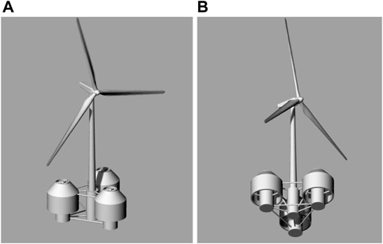
FIGURE 1. 3-D representation of the multi-purpose floating structure suitable for offshore wind and wave energy exploitation: (A) above (left), (B) below (right) sea water level (SWL) (Konispoliatis et al., 2021)
The floating system has been defined to support the DTU 10 MW reference WT (Bak et al., 2013). Regarding the three OWC devices, a Wells type air turbine is considered placed at the top of each device’s chamber, which is a bidirectional turbine designed for directional changing flows, like the ones produced in the air chamber. It is assumed that each OWC uses the same air turbine regardless of its position in relation to the wave impact. The characteristics of the air turbine can be represented by a complex pneumatic admittance Λ (Falnes, 2002), whereas in the present contribution the thermodynamic effects have not been taken into consideration. Hence Λ is considered as a real number.
Since wind and wave climate analysis has been performed (Konispoliatis et al., 2021) for three candidate installation locations, i.e., two in the Mediterranean Sea (with coordinates 35.34oN, 26.80oE and 37.30oN, 12.69oE) and one in the North Sea (with coordinates 59.42oN, 3.40oE), two turbines’ pneumatic admittances
To secure the hybrid platform, the floater is moored through a TLP mooring system of three tendons spread symmetrically about the platform’s vertical axis. The tendon system provides a structural link between the seabed and the floater’s fairleads, which are located at the bottom of the OWCs’ offset columns (i.e., at 20 m below the sea water level -SWL).
Table 1 summarizes the geometric characteristics of the examined floater, whereas in Table 2 the mooring properties are presented. Nevertheless, a detailed presentation of the selection of the floater’s specifications as well as of the design of the hybrid structure can be found in Mazarakos et al. (2018, 2019b) and Konispoliatis et al. (2021).
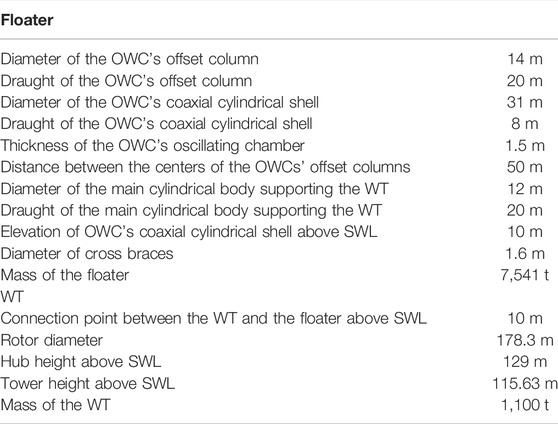
TABLE 1. Geometric characteristics of the hybrid structure.
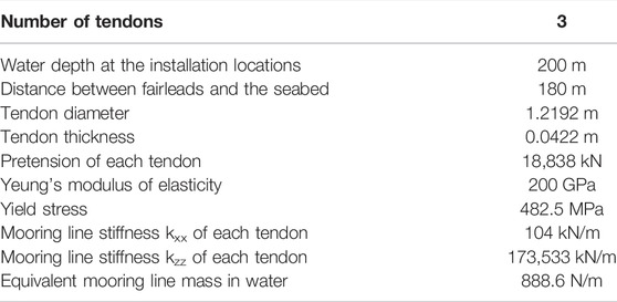
TABLE 2. Mooring properties of the hybrid structure.
3 Materials and Methods
3.1 Formulation of the Hydrodynamic Problem
The group of four bodies of the multi-purpose floating structure (i.e., three OWCs and one central truncated cylindrical body) are excited by a plane periodic wave of amplitude
In Eq. 1 the velocity potential of the undisturbed incident harmonic wave is denoted by
FIGURE 2. Definition sketch of the selected global- and local-coordinate systems.
The potentials
The velocity potential of the undisturbed incident harmonic wave train propagating at an angle
Here,
In Eq. 3,
With
The diffraction velocity potential around the body
Similar, the motion- and pressure-radiation potentials,
In Eqs. 5–7, the functions
The first-order exciting wave forces acting on each body
Here
The total exciting forces and moments,
In Eq. 9
The hydrodynamic reaction forces and moments
The complex force
In Eq. 11
In order to evaluate the hydrodynamic coefficients of the hybrid structure, the hydrodynamic reaction forces
Here, the terms
In Eq. 13
The pressure-dependent hydrodynamic forces and moments,
Here the complex term
The pressure-dependent hydrodynamic forces and moments,
Here
3.2 Coupled Hydro-Aero-Dynamic Formulation in the Frequency Domain
The translational and rotational motions of the hybrid floating structure can be evaluated by the following system of differential equations, which describes the coupled hydro-aero-dynamic problem in the frequency domain.
In Eq. 16,
It should be noted that the structure’s motion components can be expressed through the translational and angular motions,
3.3 Coupled Servo-Hydro-Aero-Elasto-Dynamic Formulation in the Time Domain.
Nonlinear time domain simulations of the coupled floating wind turbine are performed using the in-house servo-hydro-aero-elastic solver hGAST (Riziotis and Voutsinas, 1997; Manolas, 2015; Manolas et al., 2015; Manolas et al., 2020), developed at the National Technical University of Athens (NTUA). It is an integrated software for the design and verification of wind turbines, used for performing nonlinear time domain simulations as well as eigen-value and stability analysis (Chaviaropoulos, 1999; Riziotis et al., 2004). The solver has been extensively used in numerous (national and EU-funded) research projects over the last 30 years, as well as by the industry. Its predictions in offshore applications have been verified through code-to-code comparison in the OC4 annex (Popko et al., 2014; Robertson et al., 2014). Its modular form comprises:
• the “dynamic module” that defines the dynamics of the whole system.
• the “structural module” that provides the deformed shape and the associated kinematics defined for each separate component of the structure (including the mooring lines).
• the “aerodynamic module” that provides the aerodynamic loads along the rotor blades.
• the “hydrodynamic module” that provides the wave and current loading on the support structure.
• the “control module” that provides the operational conditions for the wind turbine (blades’ pitch angle and generator torque demand), regulating the power output.
A fully coupled nonlinear solution procedure is adopted. At every discrete time step, convergence is ensured not only within each separate module but also for the entire hydro-servo-aero-elastic coupled system, taking into account the nonlinear couplings between the modules. The modular definition in hGAST accommodates various options (related to the fidelity but also to the computational cost) for the physical modeling associated with a specific module. For a detailed description of the solver, the reader is directed to (Manolas et al., 2020), whereas a brief description of the options considered in the present work is given next.
3.4 Dynamic Module
In the multibody context, a local coordinate system (Figure 3A) is assigned to each component body with respect to which local elastic displacements are defined. In hGAST, the local frame of each body is subjected to rigid body and elastic motions communicated by preceding bodies as kinematic conditions imposed at their connection points. Rigid body motions can be either prescribed or controlled, while elastic motions consist of the total deflection of the previous components “transferred” to the current component. For example, the blades are subjected to elastic translational and rotational motions of the drive train and the tower (Figure 3B) as well as to rigid body motions such as the pitch motion and teetering motion of two-bladed rotors (directly imposed on the blades), azimuthal rotation, yaw rotation (indirectly imposed on the blades through the drive train and the nacelle), foundation motions or motions of the supporting structure in case of floating wind turbines (indirectly imposed to the blades through the tower) (Figure 3C). In addition to the kinematic conditions imposed at the connection points, loading conditions must also be satisfied. In particular, at each connection point, one of the connected bodies contributes the displacements and rotations to all the others, which in turn contribute their internal (reaction) loads.
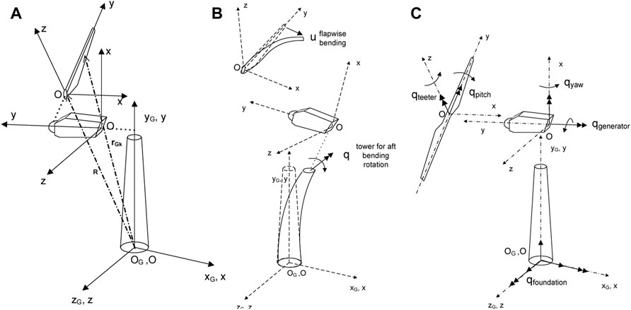
FIGURE 3. (A) Wind turbine inertial frame and local component local frames, (B) multibody kinematics realization, examples of elastic q DOFs, (C) multibody kinematics realization, examples of controlled or free motion q DOF.
The advantage of the above formulation in comparison to other multibody formulations applying the Lagrange multipliers approach is that the resulting dynamic equations of motion can be easily linearized analytically and, thereafter, linear eigenvalue stability analysis can be performed with respect to a highly deflected steady or periodic state.
3.5 Structural Module
The structural modeling is based on either linear Timoshenko beam theory or truss elements (1D structural elements only transferring axial loads) and FEM approximation. All flexible components of the wind turbine (blades, drive train, tower, members of the jacket support structure) are modeled by one or several beams with appropriate connections. Bending in two directions, including shear, tension, and torsion, is included as degrees of freedom.
The mooring lines (catenary or TLP) are modeled using the so called “dynamic modeling” with truss elements following a nonlinear, co-rotational formulation. Inertial, gravitational, and hydrodynamic loads through Morison’s equation are taken into account. The interaction with the seabed is modelled by a series of springs that are activated once the mooring line approaches the seabed surface. In addition, this formulation is able to capture non-linear geometric coupling effects, as e.g., between surge-heave and sway-heave motions that appear in TLPs.
The multibody formulation is also extended to the component level in hGAST. Highly flexible components, such as the blades, can be divided into a number of interconnected “sub-bodies,” each considered as an assembly of linear beam elements. Large deflections and rotations gradually build up and nonlinear dynamics are introduced by imposing on each sub-body the deflections and rotations of the preceding sub-body as rigid body nonlinear motions. This approach allows capturing the geometrical nonlinear effects due to large deflections and rotations using linear beam theory at the element level but considering nonlinear effects at the sub-body level (Manolas et al., 2015).
The beam model has been re-formulated to account for full stiffness matrix cross-sectional input (fully populated stiffness matrix) in order to simulate structural couplings for blade load alleviation (i.e., through bend-twist structural coupling) (Bagherpour et al., 2018).
3.6 Aerodynamic Module
Rotor aerodynamics in hGAST is simulated using an elaborated Blade Element Momentum model that accounts for dynamic inflow, yaw misalignment, and unsteady aerodynamics and dynamic stall effect through the ONERA (Petot, 1989) or the Beddoes-Leishman model (Leishman and Crouse, 1989; Hansen et al., 2004).
3.7 Hydrodynamic Module
Hydrodynamic loading for bottom-based support structures is added based on Morison’s semi-empirical equation. The relative form of Morison’s equation is adopted, considering wave kinematics (velocity and acceleration) and elastic and/or rigid body velocity and acceleration. Wave kinematics for highly nonlinear waves are defined based on stream function theory, while for irregular waves they are based on provided wave spectra (i.e., Pierson-Moskowitz or Jonswap) and linear Airy theory.
Hydrodynamic loading for floating support structures is added based on linear potential theory by solving in the frequency domain the diffraction and radiation problems and thereby obtaining the hydrodynamic mass, damping, and forcing operators needed in the dynamic equations of the floater rigid body degrees of freedom (i.e., terms
3.8 Control Module
The control module implements a baseline power controller that is a variable speed and variable pitch controller, based on linear PI elements. The controller ensures, on the one hand, operation at optimum cp maximizing power production below rated wind speed by controlling the generator torque demand, and on the other hand, speed regulation above rated wind speed by controlling the blade pitch angle and, in turn, the generated electrical power.
4 Results
4.1 Frequency Domain Analysis
The coupled hydro-aero-elastic analysis in the frequency domain, described in Sections 3.1 and 3.2, is applied for the determination of the fundamental hydrodynamic properties of the hybrid platform. In the below plots, the exciting forces and moments imposed on the entire hybrid structure are presented against the wave frequency. It should be noted that since it was assumed that the wind propagates along the positive X axis (see Figure 4), the examined angles of wave impact are in the range of
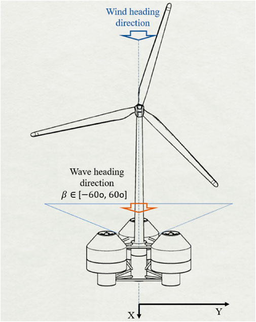
FIGURE 4. 3D definition sketch of the examined wind and wave heading angles.
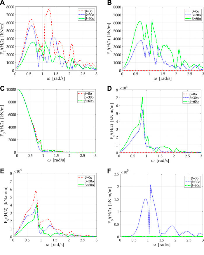
FIGURE 5. Exciting forces and moments on the hybrid structure for wave angles 0, 30, and 60 degree versus wave frequency: (A)
Figures 6, 7 depict the hydrodynamic masses and potential damping coefficients of the hybrid structure. Specifically, the coefficients
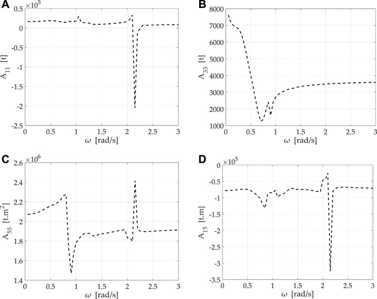
FIGURE 6. Added mass coefficients of the hybrid structure versus wave frequency: (A)
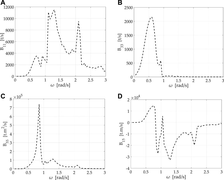
FIGURE 7. Hydrodynamic damping coefficients of the hybrid structure versus wave frequency: (A)
Regarding the potential damping coefficients, the values of
In the following figures the RAOs of the non-dimensional translational,
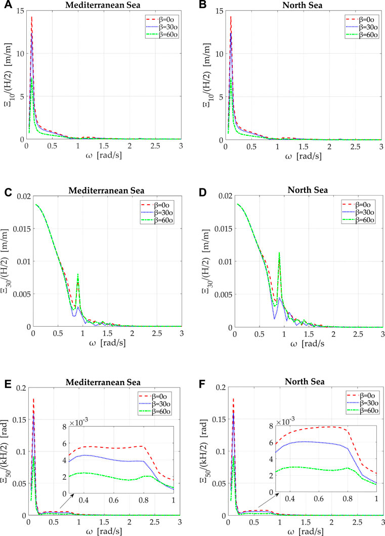
FIGURE 8. Non-dimensional translational and rotational motions of the hybrid structure at candidate installation sites, for wave angles 0, 30, 60° versus wave frequency: (A), (B)
Figure 9 depicts the structure’s non-dimensional translational,
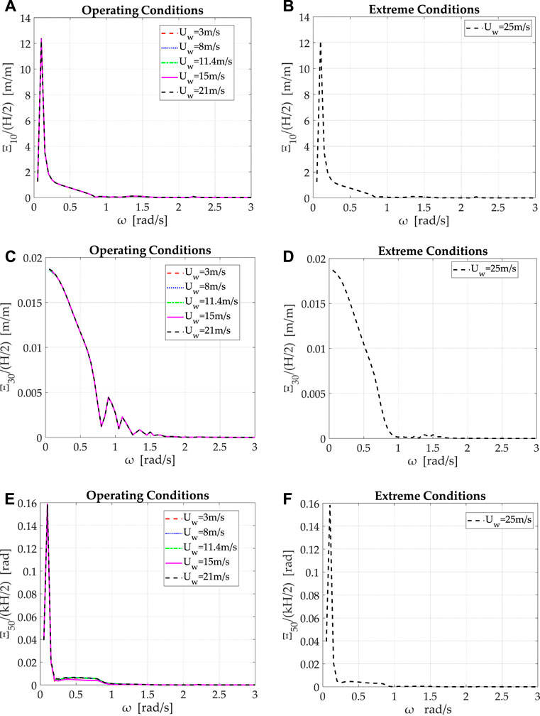
FIGURE 9. Non-dimensional translational and rotational motions of the hybrid structure at the North Sea installation location for operating and extreme environmental conditions: (A), (B)
The decrease in the structure’s motions when the OWCs’ inner air pressure is considered equal to atmospheric, is expected to discharge the mooring system by the additional loads of the air pressure distribution at extreme environmental conditions. This is verified in Figure 10 where the tension forces on the tendons of the structure at the candidate installation locations are plotted for operational- and extreme-environment conditions. Concerning the operational conditions, the examined wind velocity is indicatively considered equal to
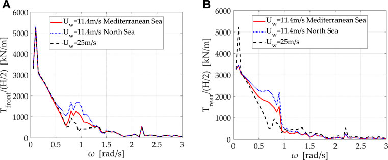
FIGURE 10. Tension forces on the front and rear tendon of the hybrid structure in the Mediterranean- and North-Sea installation locations for operating and extreme environmental conditions: (A)
4.2 Time Domain Analysis
The coupled servo-hydro-aero-elasto-dynamic analysis in the time domain, described in Section 3.3, is applied to define the fatigue and the ultimate limit states (FLS, ULS) at several joint-connections (moorings–seabed, moorings–floater, tower–floater, and blades–hub) of the coupled floating system. Table 3 presents the met-ocean data used for the two locations, one in the Mediterranean Sea, L1 (with coordinates 37.30oN, 12.69oE, see Section 2), and the other in the North Sea, L2 (with coordinates 59.42oN, 3.40oE). The table provides the most probable set of wave peak period Tp and significant wave height Hs considered, which corresponds to the normal sea state (NSS) conditions (wind speeds of 5 m/s to 25 m/s) and to the extreme or severe sea state (ESS or SSS) conditions with a 50-year return period (last line of the table). Wind conditions of IEC standard (IEC 61400-1, 2005; IEC 61400-3, 2008) sub-class C have been considered.
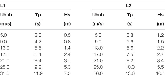
TABLE 3. Met-ocean data at the two installation locations in the Mediterranean Sea and North Sea.
In Table 4, the considered matrix of Design Load Cases (DLCs) based on the IEC standard is shown. DLC1.2 corresponds to the normal operation of the WT in normal turbulence conditions (NTM) and a normal sea state and is used for estimating the FLS. DLCs 1.3, 1.6, and 6.2 correspond to extreme conditions and are performed in order to estimate the ultimate limit state. DLCs 1.3 and 1.6 correspond to normal operation (power production) under either extreme turbulence conditions (ETM) and normal sea state, or normal turbulent conditions and a severe sea state. DLC 6.2 assumes storm conditions under wind and wave conditions with a return period of 50-years. The WT is in idling mode, the blades are pitched to a feather position at 90° and the yaw control is not functional (due to network loss). Thus, three wind misalignment angles have been considered (0°, 30°, and 60°). The OWC is only producing electrical power during the NSS conditions (DLCs 1.2 and 1.3). A 1 h realization has been performed for every case.
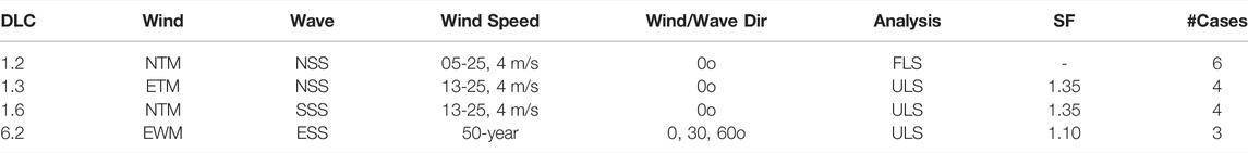
TABLE 4. Definition of DLCs for time domain calculations.
Figure 11 shows the lifetime DELs of the coupled structure for the two locations L1 and L2, calculated assuming a lifetime period of 20 years, a reference number of cycles 107 and a Wohler coefficient m equal to 10 for the blades and to four for the mooring lines and the tower. As expected, higher DELs are estimated for the location L2 in the North Sea. However, the increase in the blade moment is marginal (2% edgewise and 14% flapwise direction). On the contrary, the estimated DELs of the tower and the mooring lines are significantly higher. The DEL of the tower bending moment in the fore-aft direction increases by 50%, whereas the DEL of the mooring line tension at both positions recorded (at the seabed and the connecting point to the floater) increases by 59%.
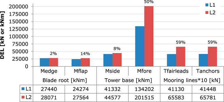
FIGURE 11. Comparison of DELs of blade root edgewise (Medge) and flapwise (Mflap) moments, tower base side-side (Mside) and fore-aft (Mfore) moments, and mooring line tension at fairleads and anchors at L1 and L2 locations based on DLC1-2. The relative percentage difference with respect to L1 is also provided above the bars.
Ultimate analysis results are discussed next. Figure 12 provides the ultimate bending moments at the root of the blade, while Figure 13 shows the ultimate values of the combined moment at the tower base and of the mooring line tension at the fairlead position. It can be seen that DLC 1-6 drives most of the analyzed signals. Further, blade moment in the edgewise direction increases by 16%, while in the flapwise direction by only 5%. The tower base combined moment significantly increases by 41%, whereas mooring lines tension by 15%. The distribution of the combined moment along the tower span at the two considered locations can be seen in Figure 14. At the stress level, the maximum developed stress at the mooring line is 326.4 MPa, which is less than the yield stress of 482.5 MPa of the steel.
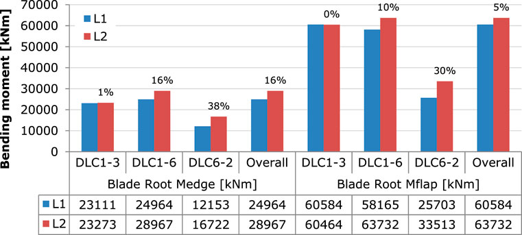
FIGURE 12. Comparison of ultimate blade root edgewise (Medge) and flapwise (Mflap) moments for the DLCs performed at L1 and L2. The relative percentage difference with respect to L1 is also provided above the bars.
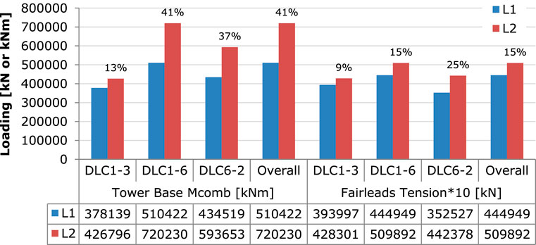
FIGURE 13. Comparison of ultimate tower base combined moment and mooring line tension at fairleads at L1 and L2 locations for the DLCs performed. The relative percentage difference with respect to L1 is also provided above the bars.
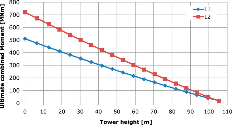
FIGURE 14. Ultimate combined moment distribution along the tower span at L1 and L2 locations.
Time series of the tension of the first (upwind) mooring line at fairleads position are presented in Figure 15 for the considered DLCs 1-2, 1-3, and 1-6 at 13 m/s, at the location L2 in the North Sea. It can be seen that the mean value of the tension is 23,800 kN, which is higher than its nominal value of 20,650 kN (pretension plus mooring line weight in water). This is attributed to the extra buoyancy applied to the floater due to the surge-heave coupling effect triggered by the thrust of the rotor. This non-linear geometric effect can be accurately accounted for by the dynamic mooring line approach adopted. The figure also demonstrates that the severe sea state conditions (DLC 1-6) drive the ultimate mooring line tension value, as mentioned above. Extreme turbulence conditions (DLC 1-3) have a minor effect on mooring line tension as the fluctuations of the corresponding time series are only slightly higher than those at normal conditions (DLC1-2).
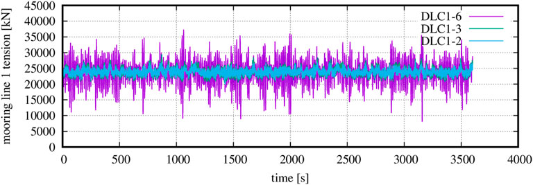
FIGURE 15. Time series of mooring line 1 (upwind) tension [kN] at fairleads position for the considered power production DLCs 1-2, 1-3, and 1-6 at 13 m/s at location L2 in the North Sea.
Finally, the effect of the OWC devices on the ultimate loads of the coupled structure, estimated through DLC 1-3, is assessed in Figure 16. Two sets of numerical simulations are considered, one with the OWC devices producing power (denoted by “with OWC” in the plot) and one considering zero pressure in the OWC chambers so that they do not produce electrical power (denoted by “w/o OWC”). The OWCs operation does not affect the WT components, as the load percentage relative differences are less than 2% for the blade and the tower signals. On the other hand, the OWC devices increase the maximum mooring line tension at fairlead position by 2% at location L1 and by 10% at location L2. Further, the presence of the OWCs reduces the ultimate minimum mooring line tension at fairlead position by 8% at location L1 and by 24% at location L2.
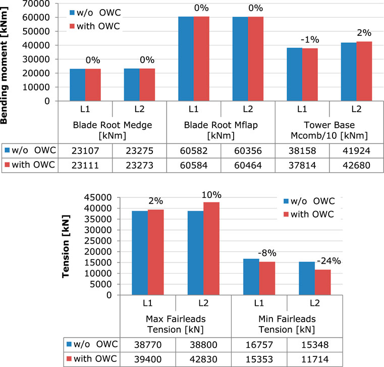
FIGURE 16. Assessment of the OWC effect on loads from DLC1.3. Ultimate blade root edgewise and flapwise moments and tower base combined moment (top) and maximum and minimum ultimate mooring line tension at fairleads (bottom) at L1 and L2, with and without (w/o) the OWC.
5 Conclusion
In the present paper, the coupled dynamic response of an offshore multi-purpose floating structure suitable for wind and wave energy exploitation is examined. The hybrid system consists of a triangular platform supported by three OWC devices at its corners and one cylindrical body in the center supporting the WT. A summary of the main conclusions from the presented analysis in the frequency and time domain is the following:
• The RAOs of the hybrid system have been concluded using a coupled hydro-aero-dynamic formulation in the frequency domain, taking into account the aerodynamic, gravitational, and inertial-gyroscopic linearized loading contributed by the WT.
• Compared to the reverse proportional effect of the incoming wave angle on the structure’s translational and rotational motions, the wind velocity does not seem to affect the responses of the system. On the other hand, the air turbine characteristics dominate the structure’s motions, affecting the heave motions more profoundly.
• The estimated first-order tension forces on the TLP tendons highlight the effect of the inner air pressure oscillation in the OWCs on the increase of the tendon loads. Therefore, the possible installation of relief valves inside each OWC has been foreseen, relieving the inner air pressure in extreme sea conditions.
• From the performed analysis in the time domain, it was found that higher tower (50%) and tendon (59%) DELs are estimated in the North Sea location. The increase in blade moments DEL is slight (2% in edgewise and 14% in flapwise direction).
• Further, DLC1.6 was found to drive the ultimate loading of most of the analyzed signals. The tower base combined moment significantly increased by 41% and the mooring line tension by 15% in the North Sea site, while the blade root flapwise moment decreased by only 5%.
• Finally, the presence of the OWCs under normal sea state conditions increases in absolute value the ultimate minimum and maximum mooring line tension at fairleads position by 24% and 8% respectively, while tower and blade loads remain almost unaffected.
This investigation can be further extended in order to examine the effect of other mooring systems (i.e., taut, catenary mooring lines) on the performance and the dynamic response of the hybrid structure under the action of both regular and irregular wave trains.
Data Availability Statement
The raw data supporting the conclusion of this article will be made available by the authors without undue reservation.
Author Contributions
DK: conceptualization, investigation, data curation, methodology, writing—original draft. DM: conceptualization, investigation, data curation, methodology, writing—original draft. SV: conceptualization, investigation, writing—review and editing. SM: conceptualization, investigation, supervision, funding acquisition, writing—review and editing.
Funding
This research has been partially financed by the Greek General Secretariat for Research and Innovation, Program Reward 2019, Title: Marine structures, for the exploitation of renewable energy sources and dissemination of results.
Conflict of Interest
Author DM was employed by iWind Renewables Private Company.
The remaining authors declare that the research was conducted in the absence of any commercial or financial relationships that could be construed as a potential conflict of interest.
Publisher’s Note
All claims expressed in this article are solely those of the authors and do not necessarily represent those of their affiliated organizations, or those of the publisher, the editors, and the reviewers. Any product that may be evaluated in this article, or claim that may be made by its manufacturer, is not guaranteed or endorsed by the publisher.
Supplementary Material
The Supplementary Material for this article can be found online at: https://www.frontiersin.org/articles/10.3389/fenrg.2022.920151/full#supplementary-material
References
Aubault, A., Alves, M., Sarmento, A., Roddier, D., and Peiffer, A. (2011). “Modeling of an Oscillating Water Column on the Floating Foundation WINDFLOAT,” in 30th International Conference on Ocean, Offshore and Arctic Engineering, Rotterdam, The Netherlands, 19-24 June. doi:10.1115/OMAE2011-49014
Bachynski, E., and Moan, T. (2013). “Point Absorber Design for a Combined Wind and Wave Energy Converter on a Tension-Leg Support Structure,” in 32nd International Conference on Ocean, Offshore and Arctic Engineering, Nantes, France, 9-14 June. doi:10.1115/omae2013-10429
Bagherpour, T., Li, X. M., Manolas, D. I., and Riziotis, V. A. (2018). Modeling of Material Bend-Twist Coupling on Wind Turbine Blades. Compos. Struct. 193, 237–246. doi:10.1016/j.compstruct.2018.03.071
Bak, C., Zahle, F., Bitsche, R., Kim, T., Yde, A., Henriksen, L. C., et al. (2013). Description of the DTU 10MW Reference Wind Turbine. Wind Energy Report-I-0092. Denmark: DTU.
Chaviaropoulos, P. K. (1999). Flap/lead-lag Aeroelastic Stability of Wind Turbine Blade Sections. Wind Energy 2, 99–112. doi:10.1002/(sici)1099-1824(199904/06)2:2<99::aid-we21>3.0.co;2-u
Cong, P., Teng, B., Bai, W., Ning, D., and Liu, Y. (2021). Wave Power Absorption by an Oscillating Water Column (OWC) Device of Annular Cross-Section in a Combined Wind-Wave Energy System. Appl. Ocean Res. 107, 102499. doi:10.1016/j.apor.2020.102499
DualSub (2019). Offshore Wind in Deep Water. Available at: https://www.marinepowersystems.co.uk/dualsub/(Accessed February 8th, 2022).
Energy (2021). Offshore Wind Market Report: 2021 Edition. Available at: https://www.energy.gov/sites/default/files/2021-08/Offshore%20Wind%20Market%20Report%202021%20Edition_Final.pdf (Accessed February 8th, 2022).
Floating Power Plant (2021). Join Renewable Energy Pioneer Fpp to Impact Climate Change. Available at: https://www.floatingpowerplant.com/(Accessed February 8th, 2022).
Gao, Z., Moan, T., Wan, L., and Michailides, C. (2016). Comparative Numerical and Experimental Study of Two Combined Wind and Wave Energy Concepts. J. Ocean Eng. Sci. 1, 36–51. doi:10.1016/j.joes.2015.12.006
Hansen, M. H., Gaunaa, M., and Madsen, H. A. (2004). A Beddoes-Leishman Type Dynamic Stall Model in State-Space and Indicial Formulation. Denmark: Forskningscenter Risoe. Risoe Report, Risoe-R-1354(EN).
IEC 61400-1 (2005). Wind Turbines-Part 1: Design Requirements. Switzerland: International Electrotechnical Commission.
IEC 61400-3 (2008). Wind Turbines-Part 3: Design Requirements for Offshore Wind Turbines. Switzerland: International Electrotechnical Commission.
IRENA (2020). Innovation Outlook: Ocean Technologies. Abu Dhabi: International Renewable Energy Agency.
Karimirad, M., and Koushan, K. (2016). “WindWEC: Combining Wind and Wave Energy Inspired by Hywind and Wavestar,” in 5th International Conference on Renewable Energy Research and Application, Birmingham, UK, 20-23 November.
Konispoliatis, D. N., and Mavrakos, S. A. (2016). Hydrodynamic Analysis of an Array of Interacting Free-Floating Oscillating Water Column (OWC’s) Devices. Ocean. Eng. 111, 179–197. doi:10.1016/j.oceaneng.2015.10.034
Konispoliatis, D. N., Mazarakos, T. P., and Mavrakos, S. A. (2016). Hydrodynamic Analysis of Three-Unit Arrays of Floating Annular Oscillating-Water-Column Wave Energy Converters. Appl. Ocean Res. 61, 42–64. doi:10.1016/j.apor.2016.10.003
Konispoliatis, D., Mazarakos, T., Katsidoniotaki, E., Vamiadakis, A., Soukissian, T., and Mavrakos, S. (2019). “Efficiency of an Array of OWC Devices Equipped with Air Turbines with Pitch Control,” in 13th European Wave and Tidal Energy Conference, Napoli, Italy, 1–6 September.
Konispoliatis, D. N., Katsaounis, G. M., Manolas, D. I., Soukissian, T. H., Polyzos, S., Mazarakos, T. P., et al. (2021). REFOS: A Renewable Energy Multi-Purpose Floating Offshore System. Energies 14, 3126. doi:10.3390/en14113126
Leishman, J., and Crouse, G. L. (1989). “State-space Model for Unsteady Airfoil Behavior and Dynamic Stall,” in Proceedings of the 30th Structures, Structural Dynamics and Materials Conference, Mobile, AL, USA, 3-5 April. doi:10.2514/6.1989-1319
Manolas, D. I., Riziotis, V. A., and Voutsinas, S. G. (2015). Assessing the Importance of Geometric Nonlinear Effects in the Prediction of Wind Turbine Blade Loads. Comput. Nonlinear Dyn. 10, 041008. doi:10.1115/1.4027684
Manolas, D. I., Riziotis, V. A., Papadakis, G. P., and Voutsinas, S. G. (2020). Hydro-servo-aero-elastic Analysis of Floating Offshore Wind Turbines. Fluids 5, 200. doi:10.3390/fluids5040200
Manolas, D. (2015). Hydro-aero-elastic Analysis of Offshore Wind Turbines. Athens, Greece: NTUA. PhD Thesis.
Mavrakos, S. Α., and Koumoutsakos, P. (1987). Hydrodynamic Interaction Among Vertical Axisymmetric Bodies Restrained in Waves. Appl. Ocean Res. 9 (3), 128–140. doi:10.1016/0141-1187(87)90017-4
Mavrakos, S. A. (1988). Hydrodynamic Coefficients for a Thick-Walled Bottomless Cylindrical Body Floating in Water of Finite Depth. Ocean. Eng. 15 (3), 213–229. doi:10.1016/0029-8018(88)90040-6
Mavrakos, S. A. (1991). Hydrodynamic Coefficients for Groups of Interacting Vertical Axisymmetric Bodies. Ocean. Eng. 18 (5), 485–515. doi:10.1016/0029-8018(91)90027-n
Mazarakos, T., Konispoliatis, D., Manolas, D., Voutsinas, S., and Mavrakos, S. (2015). “Modelling of an Offshore Multi-Purpose Floating Structure Supporting a Wind Turbine Including Second-Order Wave Loads,” in 11th European Wave and Tidal Energy Conference, Nantes, France, 7 – 10 September.
Mazarakos, T., Konispoliatis, D., and Mavrakos, S. (2018). “Loads on the Brace System of an Offshore Floating Structure,” in 13th International Marine Design Conference, Helsinki, Finland, 10 – 14 June.
Mazarakos, T., Konispoliatis, D., Katsaounis, G., Polyzos, S., Manolas, D., Voutsinas, S., et al. (2019a). Numerical and Experimental Studies of a Multi-Purpose Floating TLP Structure for Combined Wind and Wave Energy Exploitation. Medit. Mar. Sci. 20 (4), 745–763. doi:10.12681/mms.19366
Mazarakos, T., Konispoliatis, D., Soukissian, T., and Mavrakos, S. (2019b). “Significant Motions of a Multi-Purpose Floating Offshore Structure Due to Environmental Conditions,” in 13th European Wave and Tidal Energy Conference Series (EWTEC), Napoli, Italy, 1 – 6 September.
Michailides, C., Gao, Z., and Moan, T. (2016a). Experimental Study of the Functionality of a Semisubmersible Wind Turbine Combined with Flap-type Wave Energy Converters. Renew. Energy 93, 675–690. doi:10.1016/j.renene.2016.03.024
Michailides, C., Gao, Z., and Moan, T. (2016b). Experimental and Numerical Study of the Response of the Offshore Combined Wind/wave Energy Concept SFC in Extreme Environmental Conditions. Mar. Struct. 50, 35–54. doi:10.1016/j.marstruc.2016.06.005
Muliawan, M. J., Karimirad, M., and Moan, T. (2013a). Dynamic Response and Power Performance of a Combined Spar-type Floating Wind Turbine and Coaxial Floating Wave Energy Converter. Renew. Energy 50, 47–57. doi:10.1016/j.renene.2012.05.025
Muliawan, M. J., Karimirad, M., Gao, Z., and Moan, T. (2013b). Extreme Responses of a Combined Spar-type Floating Wind Turbine and Floating Wave Energy Converter (STC) System with Survival Modes. Ocean. Eng. 65, 71–82. doi:10.1016/j.oceaneng.2013.03.002
Newman, J. N. (1962). The Exciting Forces on Fixed Bodies in Waves. J. Ship Res. 6, 10–17. doi:10.5957/jsr.1962.6.4.10
Ocean Energy Europe (2020). 2030 Ocean Energy Vision. Industry Analysis of Future Deployments, Costs and Supply Chains. Available at: https://www.oceanenergy-europe.eu/wp-content/uploads/2020/10/OEE_2030_Ocean_Energy_Vision.pdf (Accessed February 8th, 2022).
Ocean Energy Ltd (2020). OceanEnergy Flagship Products. Available at: https://oceanenergy.ie/(Accessed February 8th, 2022).
Pelagic Power AS (2010). Mobilising the Total Offshore Renewable Energy Resource. Available at: https://www.pelagicpower.no (Accessed February 8th, 2022).
Perez-Collazo, C., Jakobsen, M. M., Buckland, H., and Fernandez-Chozas, J. (2013). “Synergies for a Wave-Wind Energy Concept,” in European Offshore Wind Energy Conference, Frankfurt, Germany.
Perez-Collazo, C., Greaves, D., and Iglesias, G. (2018). A Novel Hybrid Wind-Wave Energy Converter for Jacket-Frame Substructures. Energies 11 (3), 637. doi:10.3390/en11030637
Perez-Collazo, C., Pemberton, R., Greaves, D., and Iglesias, G. (2019). Monopile-mounted Wave Energy Converter for a Hybrid Wind-Wave System. Energy Convers. Manag. 199, 111971. doi:10.1016/j.enconman.2019.111971
Popko, W., Vorpahl, F., Zuga, A., Kohlmeier, M., Jonkman, J., Robertson, A., et al. (2014). Offshore Code Comparison Collaboration Continuation (OC4), Phase I—Results of Coupled Simulations of an Offshore Wind Turbine with Jacket Support Structure. J. Ocean Wind Energy 1 (1), 1–11.
REWEC3 (2019). Wave Energy. Available at: https://www.wavenergy.it/portfolio/(Accessed February 8th, 2022).
Riziotis, V. A., and Voutsinas, S. G. (1997). “GAST: A General Aerodynamic and Structural Prediction Tool for Wind Turbines,” in Proceedings of the EWEC Conference, Dublin Castle, Ireland, 6-9 October 1997, 448–452.
Riziotis, V. A., Voutsinas, S. G., Politis, E. S., and Chaviaropoulos, P. K. (2004). Aeroelastic Stability of Wind Turbines: the Problem, the Methods and the Issues. Wind Energy 7, 373–392. doi:10.1002/we.133
Robertson, A., Jonkman, J., Vorpahl, F., Popko, W., Qvist, J., Frøyd, L., et al. (2014). “Offshore Code Comparison Collaboration Continuation within IEA Wind Task 30: Phase II Results Regarding a Floating Semisubmersible Wind System,” in 33rd International Conference on Ocean, Offshore and Arctic Engineering (OMAE), San Francisco, California, USA, 8-13 June. doi:10.1115/omae2014-24040
Sarmiento, J., Iturrioz, A., Ayllón, V., Guanche, R., and Losada, I. J. (2019). Experimental Modelling of a Multi-Use Floating Platform for Wave and Wind Energy Harvesting. Ocean Eng. 173, 761–773.
Veigas, M., and Iglesias, G. (2015). A Hybrid Wave-Wind Offshore Farm for an Island. Int. J. Green Energy 12 (6), 570–576. doi:10.1080/15435075.2013.871724
Voith Hydro (2009). Voith Wave Power. Available at: https://voith.com/corp-en/index.html (Accessed February 8th, 2022).
Wang, Y., Zhang, L., Michailides, C., Wan, L., and Shi, W. (2020). Hydrodynamic Response of a Combined Wind-Wave Marine Energy Structure. J. Mar. Sci. Eng. 8 (4), 253. doi:10.3390/jmse8040253
Wind Europe (2020). Wind Energy in Europe 2020 Statistics and the Outlook for 2021–2025. Available at: https://windeurope.org/intelligence-platform/product/wind-energy-in-europe-in-2020-trends-and-statistics/(Accessed February 8th, 2022).
Wind Europe (2021). Offshore Wind Energy: 2021 Mid-year Statistics. Available at: https://windeurope.org/intelligence-platform/product/offshore-wind-energy-2021-mid-year-statistics/(Accessed February 8th, 2022).
Keywords: offshore wind turbine, oscillating water column device, TLP mooring system, coupled hydro-servo-aero-elastic analysis, extreme/ fatigue loads
Citation: Konispoliatis DN, Manolas DI, Voutsinas SG and Mavrakos SA (2022) Coupled Dynamic Response of an Offshore Multi-Purpose Floating Structure Suitable for Wind and Wave Energy Exploitation. Front. Energy Res. 10:920151. doi: 10.3389/fenrg.2022.920151
Received: 14 April 2022; Accepted: 11 May 2022;
Published: 27 June 2022.
Edited by:
Constantine Michailides, International Hellenic University, GreeceReviewed by:
Madjid Karimirad, Queen’s University Belfast, United KingdomLiliana Celia Rusu, Dunarea de Jos University, Romania
Siming Zheng, University of Plymouth, United Kingdom
Copyright © 2022 Konispoliatis, Manolas, Voutsinas and Mavrakos. This is an open-access article distributed under the terms of the Creative Commons Attribution License (CC BY). The use, distribution or reproduction in other forums is permitted, provided the original author(s) and the copyright owner(s) are credited and that the original publication in this journal is cited, in accordance with accepted academic practice. No use, distribution or reproduction is permitted which does not comply with these terms.
*Correspondence: Dimitrios N. Konispoliatis, ZGtvbmlzcEBuYXZhbC5udHVhLmdy