 Yuvaraja S
 Narayanamoorthi R
 Jagabar Sathik Mohamed Ali
 Dhafer Almakhles
- 1Electric Vehicle Charging Research Centre, Department of Electrical and Electronics Engineering, SRM Institute of Science and Technology, Chennai, India
- 2Renewable Energy Lab, College of Engineering, Prince Sultan University, Riyadh, Saudi Arabia
The recent progress in the dynamic wireless power transfer (DWPT) system brings feasibility to increase the driving range of an electric vehicle (EV). The on-road wireless charging system reduces the volume of the EV’s battery and charging the vehicle while driving. So, the powered roadways can potentially decrease the dependency on heavy-sized batteries for EV applications. The capability of transferring maximum power from the ground surface to the vehicle requires the critical design of the entire DWPT system. The various factors such as wireless charging pads, power electronic converters, compensators, and controllers influence the power transfer rate of the system. An appropriate impedance matching network assists the system during power transfer. Moreover, the design of coils in DWPT needs to consider the sensitive misalignment tolerance, safety issues, complex design, and cost factors. In this article, the basic topologies, history, and fundamentals of the DWPT charging system are discussed. In addition, the impact on the power grid due to the DWPT system and factors involved in microgrid integration are discussed. However, the current scenario of different compensators, converters, and design topologies proposed in the dynamic charging system is included. This article presents a comprehensive overview and challenges involved in a DWPT system such as the design of a power converter, charging couplers, compensation network, foreign object detection system, economic factors, and microgrid-integrated DWPT system. An economic analysis, electromagnetic compatibility, and interference of the charging system are also analyzed vastly. The human exposure level with its allowable limits developed for the wireless power transfer system is discussed.
Introduction
Electrifying road transportation is a promising technology for decarbonizing the transport industry. The climate agenda was established under the Paris agreement to reduce the emissions of carbon to control global warming, forcing the countries into transport electrification. Scientists were warned that the global temperature will increase by 3% in this century (The Paris Agreement, 2022). The problems associated with EVs are battery requirement and charging time. The capacity of the battery should be increased to extend the driving range. The required motor rating will be increased due to the rise in battery capacity. The volume of the storage device is reduced by wireless charging in driving mode. The advantages of wireless charging are safety, convenience, durability, and automatic (Patil et al., 2017). The dynamic charging system was easily installed on the driving roads. The different charging methods are battery swapping, conductive charging, and inductive charging (Yilmaz and Krein, 2013). Battery swapping (Ahmad et al., 2020) technology is a method of swapping the exhausted battery with a moderately or fully charged battery. The different swapping techniques are sideways, bottom, and rear. The complications are transposability and degradation problems. It requires complex infrastructures. The conductive charging (Mishra et al., 2021) technique is used to power the EV. It is a cost-effective and feasible method. The problem associated with conductive charging is safety and charging period. The electric current ranges and types decide the charging. The modes of charging are fast charging and normal charging. The types of EV chargers are onboard and off-board. If the power converters are installed in vehicles, then the charger is an onboard charger, and the power converters installed in the charging station is an off-board charger. An electromagnetic induction-based energization of the vehicle is called inductive power charging. Several industries adopted inductive power transfer (IPT) in charging vehicles. The charging modes of the IPT system will vary depending on the motion of the vehicle. They are static, dynamic, and quasi-dynamic wireless charging (Mohamed et al., 2020a). The process of charging in null motion of the vehicle is static charging and in motion is dynamic charging. Dynamic wireless charging (DWC) and quasi-dynamic wireless charging (QDWC) extend the driving range and reduce the storage device capacity. So, the charging system will reduce the cost of the EV. The distance and motion parameters decide the type of the transfer technique. The four technologies are near-field, far-field, mechanical, and acoustic. The frequency ranges of the different wireless power transfer technologies are KHz to MHz for an inductive and resonant inductive, Hz to MHz for a capacitive, and GHz for a microwave (Mohamed et al., 2020a). The overall structure of the article is mentioned in Figure 1.
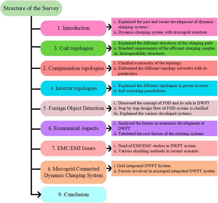
FIGURE 1. Structure of the review content.
The near-field wireless power transfer (WPT) system is classified into magnetic fields and electric fields. In an electric field WPT system, the power is transferred from one plate to another plate when both the plates are aligned, known as capacitive power charging. In a magnetic field WPT system, the power is transferred over a certain distance in an air medium from one magnetic resonator to another one when both the resonators are aligned, known as inductive power charging. The different applications of the IPT system are biomedical implants, EV charging, and home appliances. IPT charging has many benefits such as transferring power over a long gap, nearly maintenance-free, noise-free, and electrically isolated components (Mohamed et al., 2020a).
The ORNL (Miller et al., 2015) demonstrated the DWC charging and summarized the challenges experienced. The high-level precise challenges are permissible speed ranges, synchronization of coil energization and power transferring time, position of the vehicle on coils, particularly lateral alignment of pads, acceptable charging power levels and vehicle classes, effective, secure, and covert bidirectional communication.
A microgrid-connected DWC system is represented in Figure 2A. The energy resources for the DWC system are AC grid, solar and wind-based renewable energies, and energy storage devices. Renewable energy sources (RES) are intermittent sources concerning the climate. The charging power demand is satisfied with RES during peak level production by them. In addition, if the power demand level is low, then the excess energy will be stored in an energy storage device (ESD). The AC grid is utilized by the DWC system during the low-energy production by RES. The sudden rise in energy demand on the grid due to the DWC system leads to oscillation of the grid voltage and reduces the stability and reliability of the utility grid. The ESD assists the utility grid system to maintain stability. The RES energy is transmitted through the utility grid in the absence of the DWC process.
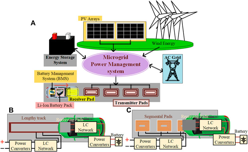
FIGURE 2. (A) Basic representation of the microgrid-integrated DWC system. (B) Elongated track DWC. (C) Segmented track DWC.
The transmitter coil is embedded on the road and the receiver coil is installed under the vehicle. The structure of the coil is dependent on application. The shapes of the coil are polarized and non-polarized. The power converters are used to energize the transmitter coil. The position of the vehicle controls the operating pulses of the power converters. The output of the transmitter side power converter is regulated by the compensation network. The compensation network is framed using passive elements. The different combinations of inductive and capacitive elements are used in the compensation network. Protracted physical charging will be replaced by automated scattered charging along motorways or business centers by QDWC (Feng et al., 2020). The challenges of the DWC system are high installation cost, misalignment tolerance, and limited speed ranges. The receiver coil receives a magnetic flux when the vehicle moves over the transmitter coil. The interacted useful flux is converted into DC power by the rectifier to charge the battery bank. Power electronic converters are used to convert the primary-side and secondary-side power. The transmitter pad and power supply units must be installed in predefined locations (Panchal et al., 2018). A long-elongated track and segmented track are the two types of transmitters in a DWPT system represented in Figures 2B,C (Farajizadeh et al., 2020). A lengthy transmitter coil is positioned along the track in an elongated type. The flux generated magnetically by the long transmitter does not have any limitations, and the ratio of produced flux to linkage flux is very small. The electromagnetic interference and exposure in non-interactive parts of the tracking coil are high. The power losses are also high due to the non-interactive part of the transmitting coil. The size of the transmitter coil influences the reliability of the system, and also, the entire coil might misbehave in case of failure in any part of the coil. In segmented DWC, the several shaped transmitter coils are arranged intermittently in the track. The transmitters may be driven by single or multiple inverters. The transmitter coil gets energization when the receiver coil moves over it. The other coil does not get energized. The switching operations of the high-frequency power electronic switches depend on the position of the EV. The energization and de-energization of the coil are performed by these high-frequency switches. The vehicle speed is a dependable factor for DWPT charging. When the receiver coil moves laterally or longitudinally, the linkage flux of the coil also changes. The maximum power will be transferred when the coils are aligned completely. When an EV moves laterally, the power transfer level would be reduced (Ahmad et al., 2017). The components of the DWPT system are transmitter side and receiver side converters, a compensation network, magnetically linked coils, and a vehicle identification system. The power inverter receives the input by a rectifier, with a power factor correction unit. The power inverter generates high-frequency ac power as per international standards. Generally, the SAE J2954 suggests the power transmission frequency to be 85 kHz. The transmitter coil is energized by this AC power, and the frequency tolerance due to misalignment will be overwhelmed by the compensation network. The compensation network is used to match the impedance of the charging pads to achieve the resonant condition under misalignment conditions. The transmitter has an open-circuit voltage in the absence of a vehicle. The receiver coil is mounted under the vehicle. The ground clearance between the coils is decided based on power levels and standards. Whenever the receiver coil is positioned over the transmitter coil, the power is transferred and the vehicle battery will be charged. The remaining segmented pads are null energized.
The induced open-circuit voltage (Voc) and circulated short-circuit current (Isc) of the fully aligned coils can be given by (Kissin et al., 2009)
The mutual inductance (M) of the coils with the coupling coefficient (k) is
where L1 is primary coil inductance, L2 is secondary coil inductance, and ω is the system power transfer frequency. An uncompensated apparent power (Su) of the receiver coil is given by
The factors involved in the WPT system are system frequency, load power, system efficiency, impedance matching, charging pad dimensions, and misalignment coupling parameters. The coils can be designed based on the rated power and frequency of the system (Ahmad et al., 2017). The SAE (SAE International, 2020) developed the standards to develop the DWC system. The specified frequency range of the transferred power is 81.38–90 kHz. So, the power inverter should consider the limits of these frequency ranges while generating high-power–high-frequency input to the transmitter coil. The design of the transmitter and receiver coils is a challenging task. The flux distribution of the transmitter coil should be uniform, and the shape of the coil should improve the magnetic flux distribution. The ferrite core has supported the coil in flux distribution. The inductive reactance of the transmitter coil is adjusted to operate at a higher frequency. The receiver coil is installed in the vehicle. The weight of the coil should not be increased beyond the acceptable standards, and the coil must be interoperable. When the coils are aligned, the maximum power is transferred from the transmitter coil to the receiver coil. The transmitter and receiver coils are coupled loosely, and air is a power transfer medium. So, the misalignment of the coil will affect the efficiency. The compensation network is integrated with coils to achieve the resonance condition. The maximum power will be transferred under this resonance condition. The institute of transportation studies at the University of California, Berkeley had shown that an inductive power transfer (IPT) system was capable of transferring 60 kW of energy to an electric system under the California PATH program (Shladover, 1992). A 3 and 50 kW inductive power charging system was developed to investigate the performance of the IPT system in urban locations under the UNPLUGGED project (Unplugged, 2015). A researcher in railroad electric traction and wireless power transfer (WPT) system in Korea Railroad Research Institute (KRRI) developed a 60 kHz, 1 MW IPT system for a length of 128 m (Kim et al., 2015). A 50 kW powered 100-m track was developed in the VICTORIA project to demonstrate the dynamic wireless charging (DWC) system. The size of the receiver coil is larger than the transmitter coil, and the coils were suitable for both static and dynamic WPT. The 20-kWh Li-ion battery pack was installed in that bus (1–8_Project_Victoria_(Bludszuweit)_8). A 20-kW prototype WPT charging infrastructure with a 100-m test track was developed as part of the FABRIC European project by the French research institute VEDECOM and its partners (Laporte et al., 2019). The DWC concept by IPT PRIMOVE is tested and proven at different test sites with a variety of vehicles. It offered a proven 180 kW continuous charging at 80 km/h (IPT Technology, 2021). The 20 and 120 kW DWC system was developed and exhibited by ORNL researchers. The system was modified to power the car and truck batteries (Department of Energy’s Oak Ridge National Laboratory, 2016; Department of Energy’s Oak Ridge National Laboratory, 2018). Stellantis, a Netherland company demonstrated a 1 MW DWC system in a 1.05 km arena circuit effectively (Stellantis, 2021). Bombardier PRIMOVE in Germany developed an inductive fast charging system in passenger service, with a 200 kW power level. Electric buses were charged within a few seconds, enabling them to cover the distance between charging stations (BombardierRail, 2014). Korea Advanced Institute of Science and Technology (KAIST) in Korea developed several online electric vehicles (OLEV) with a DWC system. A 60-kW OLEV bus was developed at the KAIST campus with 72% power transfer efficiency. In addition, 20-kW OLEV sports utility vehicles (SUVs) were designed. A 200-kW DWC system was demonstrated successfully for a distance of 544 m (Buspress, 2011; Suh et al., 2011; Jeong S. et al., 2019). Utah state university demonstrated DWC technology with a 25-kW electric bus on its electric vehicle and roadway track in 2016. In addition, the vehicle was operated by 30-kWh Ni–cd battery packs (Utah State University Science and Technology, 2012; Tavakoli and Pantic, 2018). The University of Ottawa tested the dynamic charging system in the connected and autonomous electric vehicle (CAEV) transport system funded by the Ontario government. The system helped to reduce the congestion in charging stations (Vaidya and Mouftah, 2020). Wireless Charging of Electric Taxis (WiCET) project executed by lumen freedom to test the feasibility of wireless charging for electric taxis in the United Kingdom under the office for zero-emission vehicles (OZEV) scheme (WiCET, 2021; Lumen Freedom, 2022). A 30-kW DWC system for the Artega electric sports car and a 60-kW DWC system for an 18-m auto tram electric bus were developed by INTIS technology (INTIS, 2018). WiTricity Corp developed an 11-kW stationary wireless charger and tested it with a Tesla 3 model electric vehicle (WiTricity, 2022). A Conductix-Wampfler (Conductix, 2022) from the Delachaux group developed a 6–35 kW IPT floor and rail system, and they also installed an IPT charging system in Torino public transport, Italy (Eltis News Editor, 2015). Qualcomm from New Zealand demonstrated the profits of Qualcomm Halo’s dynamic wireless charging for electric vehicles. The 100-m track is powered by 85 kHz, 2*10 kW interoperable charging pads demonstrated with a formulae race car (Graeme Davison Vice President, 2017). Table 1 is representing the state-of-art in the static and dynamic charging systems, respectively.
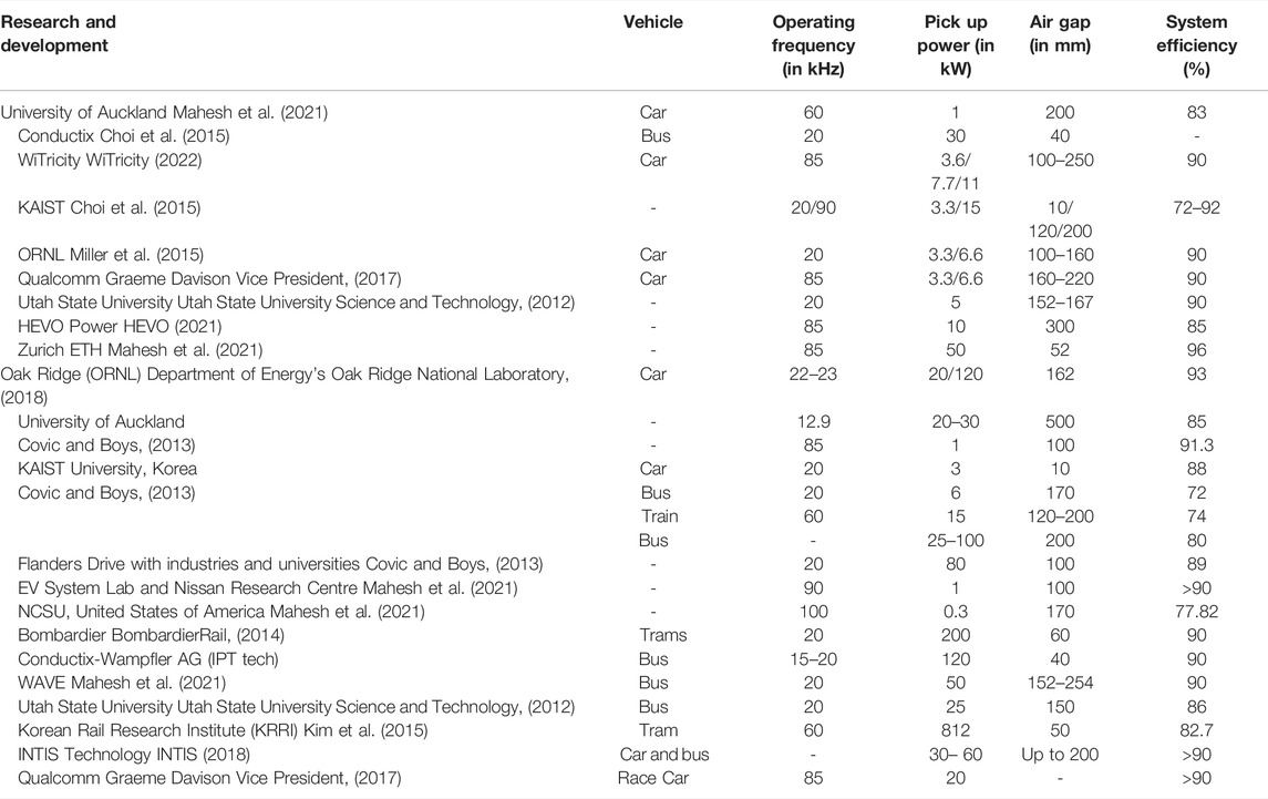
TABLE 1. Development of Static wireless charging (SWC) technologies. Development of DWC technologies.
Coil Topologies
The IPT system uses two coils to transfer power. The coil assembled in-ground is considered a primary coil or ground assembly (GA), and the coil assembled in a vehicle is considered a secondary coil or vehicle assembly (VA) (Patil et al., 2017). The coils are coupled with each other magnetically in the air core. A primary stationary coil transfers the power to a moving secondary coil in an air medium. The magnetizing inductance of the coil is lesser than the leakage inductance in between the coils in a loosely coupled coil structure. The selection of coil structure will be based on particular applications (de Marco et al., 2019). The power-transferring distance, power rating of the system, coupling parameters such as inductance and quality factor, proper ventilation, misalignment tolerance, interoperability, and cost are the deciding factors to design the coil structure that is coil size and coil shape. The ferrite core is used to improve the quality factor and the magnitude of coil inductance. The single coil producing vertical flux alone is known as a non-polarized coil, and an additional coil structure used to produce horizontal flux is known as a polarized coil (Mohamed et al., 2020a). Circular pad (CP) coils are suitable for stationary wireless power charging. It has low leakage flux, compact design, flexible design, and low eddy current due to the absence of sharp edges (de Marco et al., 2019). Due to these characteristics, it can be easily installed on grid side and vehicle side. But the performance of the CP coil will be affected by incremental variations in the air gap between the coils (Bouanou et al., 2021). In addition, the flux distribution of the coil is limited to diameter. The different coil geometries are non-polarized structure such as circular, rectangular, square, hexagonal, and polarized structure such as double-D, double-D quadrature, bipolar, and tripolar. The rectangular and square coils are creating a higher flux path than the CP coil. These coils have high misalignment tolerance compared with other coil designs. The sharp edges are increasing the eddy current loss (Luo and Wei, 2018). The flux pipe coil has high lateral misalignment tolerance and k compared with the circular pad (Mohamed et al., 2018). But the quality factor will affect intercepting flux due to shielding. To overcome the disadvantages of circular and flux pipe coil structures, the double-D (DD) coil was proposed (Zaheer et al., 2015). In this DD coil, the height of the flux path is directly proportional to half the receiver pad’s length. The coil features are improved no-load quality factor, higher misalignment tolerance, lesser aluminum shielding loss, higher coefficient of coupling, and reduced flux leakage in the coil backside (Lin et al., 2015). The DD coil is producing horizontal flux only, so it is non-interoperable with non-polarized pads (Song et al., 2020). The additional quadrature coil is added with the DD coil to produce vertical flux, and it is named as double-D quadrature (DDQ) coil. It has high misalignment tolerance and is interoperable with all the coils. But, two synchronized inverters are required to operate those coils (Budhia et al., 2013). The bipolar pad (BP) coil structure was introduced to reduce the usage of copper by the DDQ coil and it has the same advantages as the DDQ coil. But the cost and complexity of the bipolar coil are high (Jafari et al., 2021). A three mutually decoupled coil structure named a tripolar pad is designed to improve rotational misalignment tolerance. It has lesser apparent power demand and leakage flux (Kim et al., 2017). But the decoupled coils are driven by a separate inverter and it will increase the cost and complexity (Hossain et al., 2022). Charging the vehicle in ordinary motion and slow motion is known as dynamic wireless power charging.
The types of power rail tracks are elongated or segmental. The long track coil is used in elongated types. In terms of magnetic concern, the ratio of linkage and leakage flux is low in elongated. Due to this, high electromagnetic interference and high electromagnetic exposure are caused by non-contracted points. The power losses are high due to the non-interacting part. The segmental coil contains multiple coils driven by multiple or single converters. The transmitter coil will be energized when the receiver coil is aligned with the particular transmitter coil (Mohamed et al., 2020a), so that, the power loss will be reduced and the energization of non-interactive coils could be avoided. The restrictions of these segmented transmitters are that the transmitters should be closely spaced and higher rating converters and compensators.
The static WPT coils are also suitable for dynamic WPT systems. The performance of the transmitter track in a DWPT system will be improved by ferromagnetic material with different structures, that is, W, I, E, U, S, etc. The different polyphase tracks are used to increase the misalignment tolerance, increase the power capacity with less stress, and supply constant power. The transferred energy by the transmitter coil to the receiver coil in a DWPT system is (Miller et al., 2015)
where D is the covering distance.
E is the energy transferred.
ωs is the angular frequency.
IT is the transmitter coil current.
RL is the receiver coil load resistance.
Ma (x) and Mb (x) are the mutual inductance at x position by the transmitter coils b and a (Figure 3). From the aforementioned equation, the energy transferred by the transmitter coil is inversely proportional to the speed of the EV. But, the transferred energy completely in a particular interval is independent of EV speed. The components of the transmitter pad are conducting Litz wires to design a coil, a ferromagnetic core for uniform distribution of magnetic flux, and magnetic shielding to reduce exposure levels. In the high-frequency operating ranges, the eddy current loss is high due to the skin and proximity effect. In addition, to improve the quality factor, the resistance of the conductor should be reduced. So, the Litz wire is generally a multi-stranded wire used as a conducting wire to reduce those effects and will improve efficiency. The Litz wire strands are decided based on the rated current of the system. The coil geometry is decided based on the system power and frequency. Mutual inductance and rated power of the system are used to decide the spiral coil turns (Zhang et al., 2015). As per Sullivan (1999), the system frequency is the main parameter to decide the thickness and number of strands of the conductor.
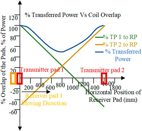
FIGURE 3. Characteristics of power transfer (Miller et al., 2015)
As per SAE International (2020), the operating frequency of the coils is 85 kHz. The recommended American wire gage to use the conductor in the mentioned operating frequency is 38. Generally, the Litz wire is preferred in the high-frequency operating regions to reduce the eddy current losses. Some researchers (Sullivan, 2001) analyzed the efficiency of the Litz wire with a magneto-plated aluminum pipe, which has low cost and nearer efficiency to Litz. The construction of the Litz wire assists the system in the reduction of proximity and skin effect, which are disturbance effects in a high-frequency system. The resistance of the wire also decreased by twisting the conductors. The ferromagnetic core is utilized to direct the flux lines produced by the transmitter toward the receiver. They acted as flux concentrators and helped to improve the coupling factors. Also, it will support the coils mechanically and magnetically. In general, the ferrite bar is used as a core in many coil designs. The coupling factors will be improved by a surplus in the number of ferrite cores. An EMF exposure in a high-frequency power transfer system is high and also it may surpass the safe limits reported by international standards. So, EMF shielding is necessary to diminish the flux leakage around the system. The different types of magnetic shielding are passive shielding, active shielding, and reactive shielding.
Aluminum will be used as a shielding material in maximum applications due to its affordable cost and availability. The ferrite backplate is preferred for shielding in very high-power transfer applications. A modified nanocrystalline core offers higher flexibility, saturation, and better stability than the ferrite core, and additionally it is preferable for high-power wireless charging (Xiong et al., 2021). Different coil structures are compared in Table 2. The shielding of the transmitter coil side is used to block the flux passing outside the coil arrangements. An eddy current loss will be reduced by shielding. The receiver coil shielding is protecting the user by avoiding the magnetic flux passing inside the vehicle chassis, so that, human safety will be ensured by shielding. ICNIRP-derived standards for electromagnetic exposure limit for humans (Ziegelberger et al., 2020). A polyphase track is used to provide short power boosts to EV and continuous power transfer without onboard batteries along the roadways without complex pickup structures or restricted driving zone (Covic et al., 2007). A meander type (Wang et al., 2020) track is the ideal track to charge the rail vehicles. A uniform power transfer to pickup the coil is achieved by this structure (Matsumoto et al., 2018). Increasing the width of the ferrite core will decrease the leakage flux. Some tuning will likely be required if pads are designed for variations over a wide Z-axis range. Series tuning is recommended for non-polarized pads, such as circular pads, while parallel tuning is recommended for polarized secondary pads, such as solenoid pipes and bipolar coils (Lin et al., 2015). The power density can be maximized by combining multiple coils in a polyphase system. The ferrite cores help the system balance the current.
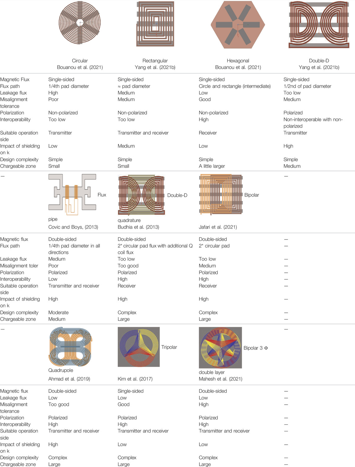
TABLE 2. Comparison of different coil topologies.
Interoperability
Interoperability is a vehicle-friendly parameter where the power transfer ability of the coil is independent of the receiver coil geometry and power. The secondary and primary coils should effectively couple with each other. The receiver coil should accumulate the transmitter coil flux effectively both from parallel and perpendicular field patterns (Zaheer et al., 2015). An interoperability study will help the designer to design a highly efficient loosely coupled transformer. The loosely coupled transformers can be designed to obtain the maximum coefficient of coupling (k). The maximum k may be obtained without misalignment or the most awful misalignment. The critical pad design considers that the ability of a coil should be independent of the symmetrical coil shape. As per international standard SAE J2954, electric and magnetic interoperability in the WPT system is proposed (Yang et al., 2021b). Electrical interoperability depends on power converters, and impedance matching networks. Magnetic interoperability depends on transmitter and receiver pad coil parameters. However, the circular pad coil and DD pad coil have the worst interoperability characteristics with each other. When either of the pads is centrally aligned with the other one, it will be proven zero-coupled power. The circular coil produces vertical flux, and a DD coil produces horizontal flux. A DDQ pad will have good interoperable characteristics with the CP coil and DDP coil systems. Also, it will increase the charging zone compared with non-polarized pads. Normally, the DDQ and BP pads are more suitable on the receiver side to capture the maximum field pattern. The quadrapule coil structure is introduced, and it has maximum coupling coefficient with the DDQ coil compared with other rectangular and DD coils. The quadrapule coil has low k and M values due to the additional quadrature coil (Ahmad et al., 2019). A new multi-coil ground assembly has interoperability with CP and DDP structures without significant misalignment (Lin et al., 2020). A power decomposition based on the interface impedance method SAE J2954 proposed an interoperability evaluation method (Yang et al., 2021a).
But the method is not applicable for practical applications due to phase angle measurement. A variable step perturbation and observation (VSPandO) based position adjustment algorithm was proposed (Yang et al., 2021b) to improve interoperable characteristics between the RP and DDP coils. The position of the pad is adjusted by sensing DC offset. The methods to make compatible pads are changing pad structures and controlling coil currents. The features of various interoperability techniques are tabulated in Table 3. An SAE J2954 developed certain guidelines to design a DWPT system effectively. The limits on in-vehicle power levels are mentioned in Tables 4, 5. The power levels specified the maximum limit of apparent power drawn from the grid. The aforementioned system’s efficiency is achievable with symmetrical coils and specified vertical limits. The transmitter and receiver coil should be spaced by some distance. The vertical distance between the coils can be classified into the different Z classes that are specified in Table 4. The different interoperability pad combinations are represented in Figure 4.
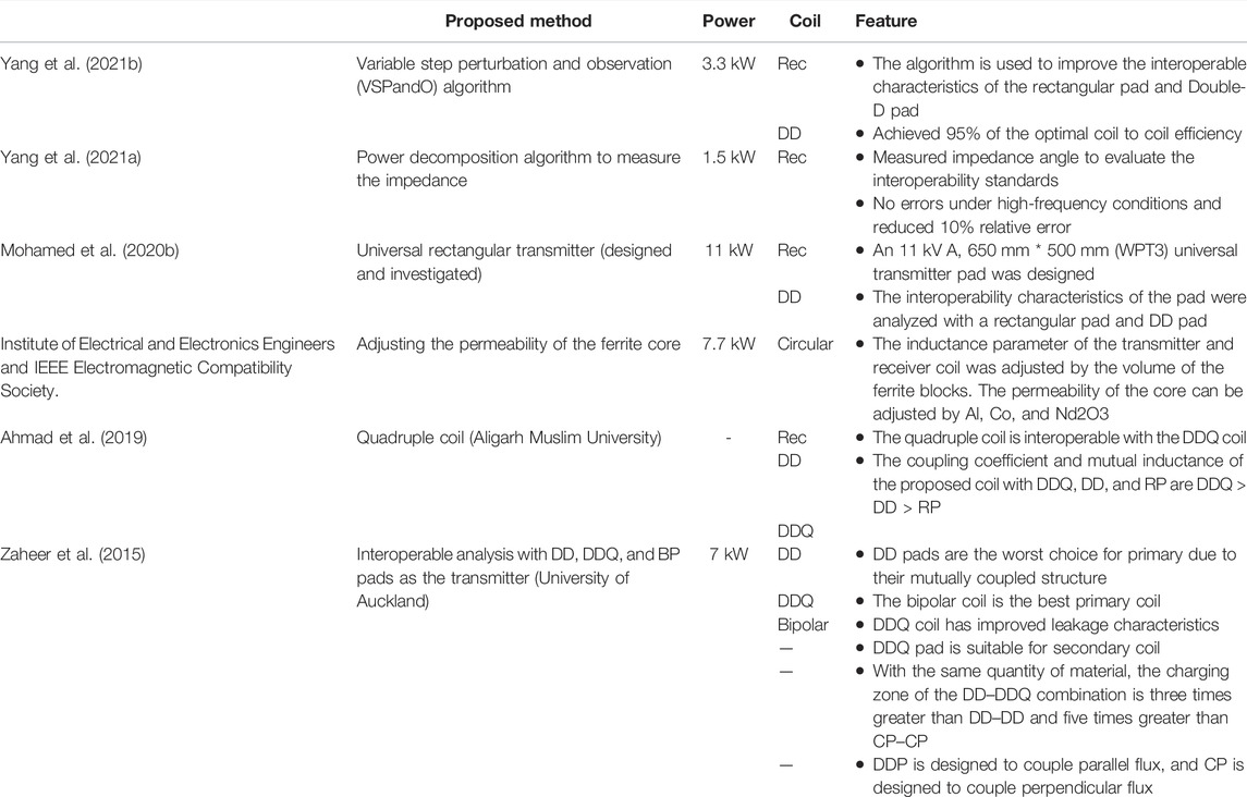
TABLE 3. Analysis of interoperability.
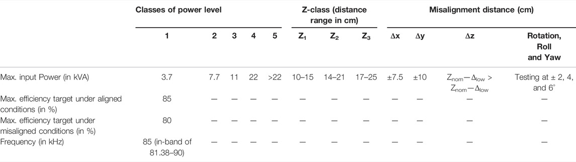
TABLE 4. SAE J2954 vehicle power levels (SAE International, 2020).
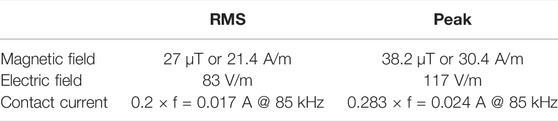
TABLE 5. EMF exposure level (operation frequency range 3 kHz—10 MHz) (Ziegelberger et al., 2020).
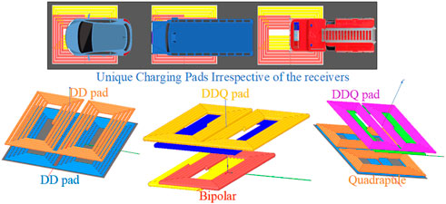
FIGURE 4. Representation of the interoperability and interoperability coils (DD–DD, quadrapule-DDQ, bipolar-DDQ).
The allowable ranges for lateral and longitudinal misalignment tolerance of the vehicle during the charging process are specified in Table 4. The misalignment tolerance between vehicle assembly and ground assembly in the X-axis and Y-axis should be considered. The EMF exposure levels for the living objects developed by ICNIRP (Ziegelberger et al., 2020) and the allowable limits developed as an international standard by them are mentioned in Table 5. The specified limits apply to the system with 3 kHz–10 MHz operating frequency level.
Compensation Topologies
An inductive power transfer system contains loosely coupled coil structures and misalignment problems. The leakage inductance of the coils is high due to dynamic operation (Sohn et al., 2015). The power transfer capability of the coils suffers due to high leakage inductance, and efficiency also decreases quicker as misalignment increases. This high leakage inductance can be compensated by reactive power compensation. So, the reactive power is compensated by passive resonant networks. So, the ability of the coil to transfer maximum power would be improved (Zhang and Mi, 2016). The objectives of the various compensation topologies are to compensate the VAR, achieve soft switching, obtain constant CC/CV output, maximize the power transfer profile and efficiency, tolerate misalignment issues, minimize VA rating, and avoid bifurcation.
These topologies are assisting the system in rated apparent power minimization and soft-switching operation. Also, constant output voltage/current in a network is maintained by these networks. The different types of compensation networks based on passive elements are mono-resonant and multi-resonant (Shevchenko et al., 2019). The four general compensation topologies in mono-resonant compensation are S–S (series–series), P–P (parallel–parallel), S–P (series–parallel), and P–S (parallel–series) (Mahesh et al., 2021). The addition of passive elements in the mono-resonant network to attain output voltage/current constantly under independent load conditions is considered in a multi-resonant network. The LCC–LCC, LCC–SP, LCC–S/P, and LCL–LCL compensation networks are the classifications of multi-resonant networks.
Bifurcation (Jayalath and Khan, 2021) is the phenomenon occurring on the primary side due to input impedance or admittance. It is generally known in the system which has more than one zero phase angle frequency or resonant frequency. The different zero phase angle frequencies are depending on loading conditions and passive components value. Zero phase angle division is generally called bifurcation. Bifurcation region system control is entirely different from the single zero phase angle region. So, the study of bifurcation is also necessary for dynamic wireless power charging conditions. The coils of the system must be designed carefully to avoid bifurcation. The quality factor (Q) dependency of the bifurcation is specified in Table 6. The compensation network is used to control the primary and secondary quality factors (Qp, Qs). The source current and load current increased due to decreases in total impedance (ZT) of the network in S–S and S–P topologies. Due to misalignment, the total impedance of the network increases, forcing a source current, and load current to fall (Bagchi et al., 2021). The stability of the system should be independent of the load for wide ranges of frequency changes. So, the network should be designed for one zero phase angle. The selection of compensation topology is based on applications. A parallel compensation is well-matched for high current concentrated windings, and a series compensation is a better choice for long primary tracks, that is, segmental primary tracks where the k varies with the lateral coil movement. The parallel compensation could not transfer rated power during misalignment and series compensation could transfer the power during misalignment conditions. But parallel compensation is safer than series in the absence of receiver (Villa et al., 2012). The magnitude of current and voltage are high in series compensation compared with parallel (Villa et al., 2012). In the multi-resonant network, the LCL/LCC topologies are used in DWPT charger circuits for an EV. The constant current should be maintained in the track. These topologies are better than other multi-resonant complex topologies and will provide an efficiency greater than 95% (Cheng C. et al., 2020). The LCC compensation network is independent of load conditions and k. This compensation assists the secondary side for unity power factor pickup. The dual side LCC compensation has high misalignment tolerance, independent load characteristics, improve efficiency, and the current stress across the high-frequency switches can be reduced. With the LCC compensation, zero current switching and zero phase angle operation can be achieved simultaneously (Chen et al., 2020). The output power can be controlled by the dual LCC network while maintaining the high-power factor without the help of dc–dc converter and communication between the transmitter and receiver (Luo et al., 2022). In a closed-loop system, dual side LCC topology is used to attain constant output voltage, which reduces a converter’s effort. The LCL network is used to retain constant current output in the track even though the reflected impedance by the receiver changes. Also, it helped to reduce the loading reactive power on the transmitter track. In this network, the total power is considered as active load power and resonant network losses. The reactive power circulates within the tank LC circuit. The inverter switches rating is reduced due to low-power demand.
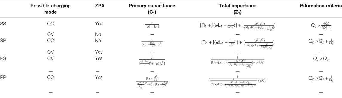
TABLE 6. Equations involved in basic compensation topology networks.
In this LCL–SS topology (Wang et al., 2021) is used to attain constant load voltage independently, LCL–LCL topology (Keeling et al., 2010; Nguyen et al., 2021) is used to attain constant load current independently, and both the topologies are used to recognize zero phase angle (Wang et al., 2021). Although the multi-resonant networks are more advantageous for dynamic wireless power transfer, the copper loss is due to additional resonant components higher than mono-resonant networks. The complex control method is required in modified networks (Triviño-Cabrera et al., 2020). The S–SP network is less sensitive for wide load variation ranges and k ranges and high efficiency is achieved for high-load resistance by the LCC–P network (Lu et al., 2019). The different equations mentioned for four basic topologies in Table 6 are used to calculate the primary capacitance and total impedance, and also in Table 6 possible charging modes and possible zero phase angle modes are specified.
In summary, the S–S topology provides a constant output current under resonant conditions and a high no-load current. Also, the ZVS capability of the topology is simple and it can be operated with other networks. Though the topology is simple, its coupling nature is poor. The modifications in S–P topology help the system in an automatic coil energization process. But the impedance reflected by the capacitor will affect the ZVS capability of the system. In a low-inductance system, the P–P topology is preferable. Hence, the current fed inverter affects the ZVS operation, and the voltage stress of the switches is increased. Overall efficiency will be maintained higher (up to 96%) under the worst condition also by using LCL topology. The current stress of the semiconductor switches is reduced by maintaining a constant current. The LCL topology is better to use under light load conditions. The control characteristics of the LCC network are simple on the primary side and the unity power factor will be achieved easily. The constant current will be maintained on both sides and hence the switching stress is reduced. The additional passive element is used in LCL/LCC topology to attain high efficiency in high-power ranges with constant output current. This will be attained without affecting load and k characteristics. The advantages, disadvantages, and applications of different compensation topologies are represented in Table 7.
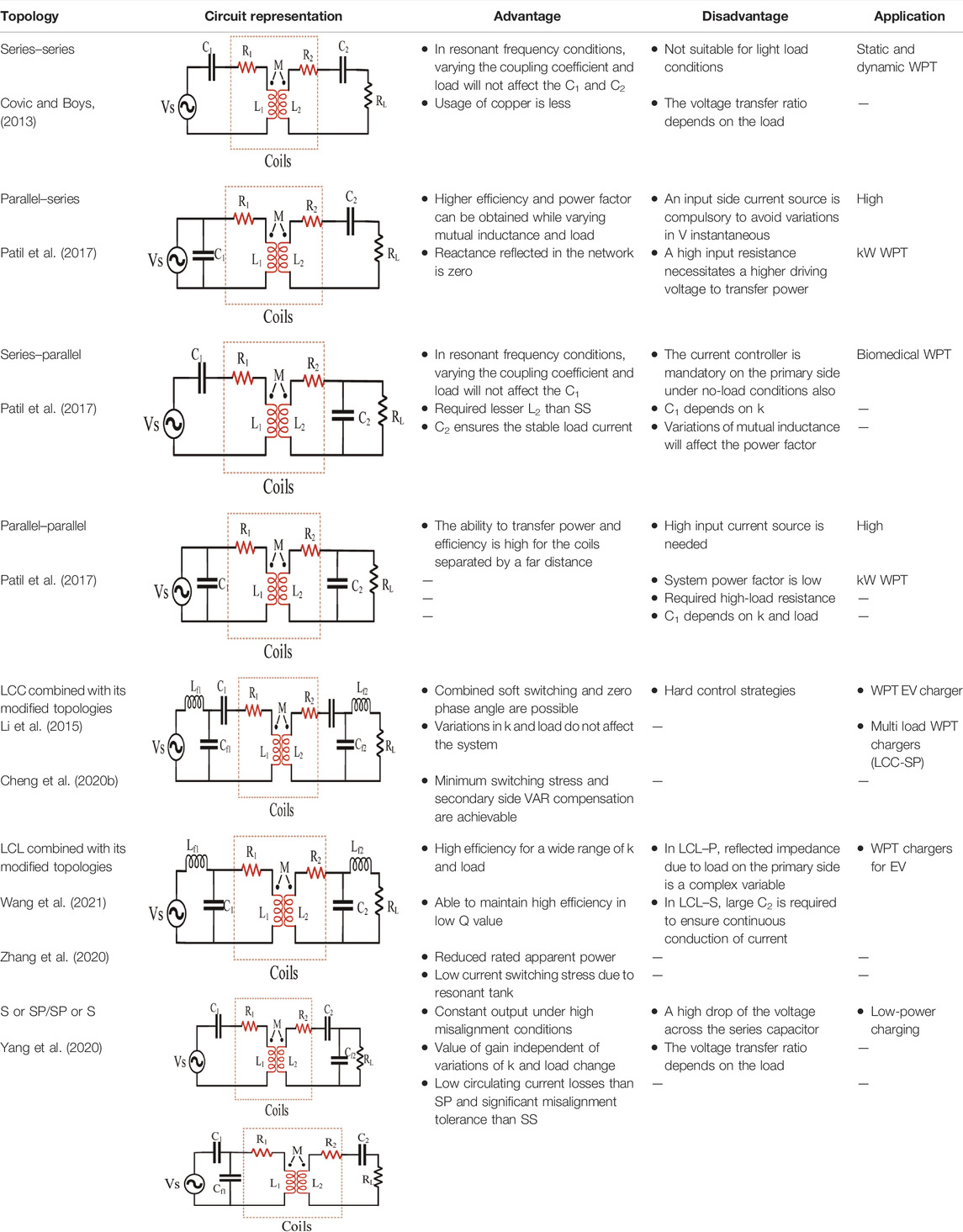
TABLE 7. Comparison of mono-resonant compensation topology networks.
Inverter Topologies
The transmitter coil is laid on the roadside energized by the inverter circuit. As per SAE J2954, the operating frequency of the inverter must be 85 kHz, and the power rating of the switches is decided by the charging capacity. The number of roadway-positioned transmitter coils can be energized by a single inverter or multiple inverters. The main objective of the inverter is to generate AC power with high frequency to energize and de-energize the transmitter coil. The switching losses of the inverter should be minimum. The switching stress will be reduced by soft-switching, which is assisted by the compensation network. The driver circuit of the inverter should generate high operating frequency pulses based on the vehicle position. The features of different inverter topologies are mentioned in Table 8. As per Sanken Electric Co., Ltd (2022), the conventional Si power semiconductor switches are replaced by wide-bandgap devices such as SiC and GaN switches. The high power, high-frequency SiC, and GaN switches have low on-state resistance, high-temperature coefficient, and high figure of merit. A single inverter can be adopted to energize the transmitter coils (Fujita et al., 2017; Mai et al., 2017; Chen et al., 2018; Vu et al., 2019). In this method, four switches are used irrespective of the coils, that is, several switches are independent of the number of coils. The simple switching control, the power rating of the switches increased, and the complexity in the operating regions increased when a single resonant inverter is used for all the coils. The power stress of the inverter is high. The coils are connected in series or parallel, the losses in the uncontacted coil are due to energization by inverter current. The individual inverter is used to energize the individual transmitter coil, which is positioned in the roadway (Guo et al., 2016; Li et al., 2018; Zhou H. et al., 2021; Lee et al., 2022). Multiple coils are energized by parallel inverters. The power rating of the inverter switches is reduced in this method. But the switching losses increased due to a high number of switches. The 4N switches are used for the N number of coils. The N-legged converter (Farajizadeh et al., 2020) is proposed to overcome the drawbacks of previously mentioned inverters. The power flowing in the transmitter coil is effectively controlled by this N-legged inverter and the efficiency is improved. The proposed inverter requires 2* (1 + N) switches to drive the N coils. The converter has parallel-connected N legs and provides N-1 output terminals. The transmitter coils are closely spaced to transfer uniform power, and the power losses are also reduced by controlling current flow in non-interactive coils. A push–pull-driven coupler array (Barsari et al., 2021) was designed with a fewer number of semiconductor switches. It requires N+1 switches to energize N windings. Any switches can be activated proportionally without increasing the current stress. A Z-source converter is proposed by González-Santini et al. (2016) to regulate the output voltage, with power factor correction without adding additional semiconductor devices. The reliability of the system also increased by using the Z-source network. A new topology, an integrated boost multilevel converter (IBMC) (Wang and Thrimawithana, 2020), containing half-bridge modules which are series-connected in both side arms and connected with a DC source with a series-connected dc inductor. The power flow in this converter is regulated effectively with boosted multilevel voltage in the absence of a vehicle side regulator. The power level of the inverter is improved by a multi-phase multi-inverter (Deng et al., 2017, 2019a, 2019b; Zhu et al., 2021), and the total input current is shared by all parallel phases. The multi-phase inverter topology regulates the output voltage and system efficiency. The power loss also decreased due to low-power dissipation by semiconductor switches. A high-frequency bridgeless rectifier is used (Mishima and Morita, 2017) to decrease the switching noises and progress the efficiency. The output power is regulated by introducing PWM on the receiver side (Wang et al., 2022). A conventional voltage-fed full-bridge converter is substituted by a dual-independent output inverter (Ge et al., 2019; Liu et al., 2020). The modified inverter drives the segmental track with a fewer number of switches compared with a conventional full-bridge inverter. A modified magnetic coupler is presented on the vehicle side (Kalra et al., 2020; Hsieh et al., 2021; Shi et al., 2022) to reduce the volume of a magnetic coupler. The output voltage of the system is regulated effectively and the power transfer capability of the coupler will be improved. The output power is regulated by an inverter with a double half-bridge (Zhu et al., 2022) and two-variable inductors.
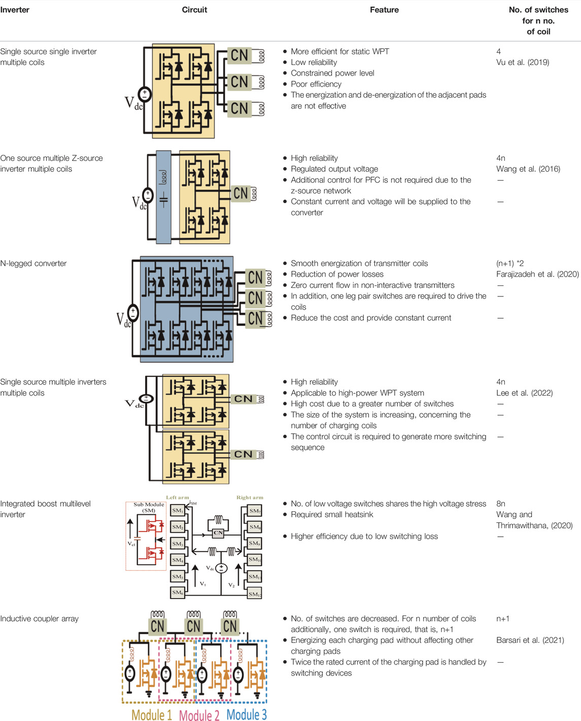
TABLE 8. Comparison of inverter topologies.
Foreign Object Detection
The coil positioned on the roadside transfers the power in the air gap, whenever the receiver coil is positioned over it. Instead of a receiver coil if any metal object is placed on the coil, the power will be transferred to that metal object due to the high magnetic field between the coils. The transferred power circulated in metal objects and eddy current losses occurred in the form of heat and fire may be occurred under the worst condition (Xiang et al., 2019). If the object placed on the coil has sufficient mass, the rated power will be circulated through the object. In addition, the object will affect the inductance parameters (L, M, and k). So, it is necessary to detect the introduction of a foreign object in a charging zone to avoid efficiency reduction and unwanted temperature increase. Because the temperature of the foreign object increased based on its magnetic permeability (Jafari et al., 2019), various thresholds can be used to determine whether or not the foreign object may cause a significant problem. The basic diagram of FOD is represented in Figure 5.
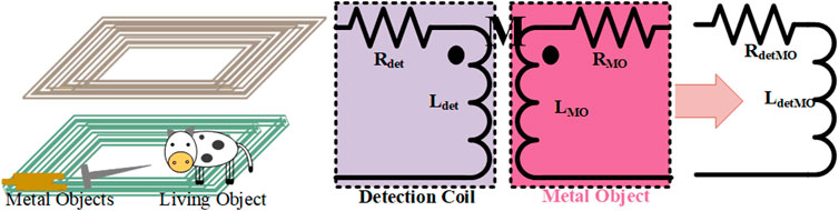
FIGURE 5. Representation and equivalent circuit of FOD.
Foreign object detection (FOD) can be classified into MOD (metal object detection) and LOD (living object detection) based on the power level and detecting objects (Zhang et al., 2019). FOD can also be classified based on system parameters, field-based detection, and wave-based detection. Normally, the system parameter detection method is used in low-power systems, and the other two methods are used in low-power systems and high-power systems. In the high-power transfer system, the air gap is large. So, LOD is applicable for this system only. But MOD applies to high- and low-power applications. A system parameter detection method, considers non-electrical parameters to detect the metal object. The pressure and temperature sensors are used to sense the changes in pressure and temperature due to metal objects. But these sensors are unable to identify the difference between metallic and non-metallic objects.
The electrical parameter method detects the changes in power due to eddy current induced in a metal object in a charging zone. It is suitable for wireless charging of low-power consumer electronics. The transmitter coils are unenergized initially. The low-magnitude power signal is allowed through the coil to measure parameter values (P, V, and I). If the signal is received, the rated power will be transferred to the receiver coil. If not, the measured parameters are compared with threshold limits. If the signal exceeded the threshold value, the foreign object was detected. It may be a living object or a metal object. Then, the necessary action should be taken by the operator. If the parameter values are within the threshold value, the presence of a foreign object was not found and takes time to send the next energized signal. An extra sensing device is required in the wave-based detection method to detect the existence of the object. An imaging camera is used to detect the object and ultrasonic, radar sensors are used to measure the changes in the distance of the transmitter coil from the sensor due to the metal object. Among all the detection method, the field-based detection method is popular and detects the metal object by passive parameter (inductance and capacitance) changes (Patents, 2022). The detection method for LOD is primarily for high-power applications where the living objects interfere with the charging zone. A single-layer sensing coil (Jang G. C. et al., 2016) is fabricated with a minimum number of components to detect the changes in the magnetic field of the system more accurately. In addition, a non-overlapping coil (Jeong et al., 2018) senses the variations in magnetic flux and induced voltages and detects the position of the vehicle (DoP) and metal object.
A rectangular-shaped two-layer symmetrical detection coil detects the foreign objects accurately by comparing the difference between two symmetrical coil voltages (Xue et al., 2022) or mutual inductances. A multiple loop parallel mistuned resonant coil (Jeong S. Y. et al., 2019) mounted on the transmitter coil detects the metal objects sensitively based on changes in the coil’s self-inductance. The foreign object materials of the system are recognized by a hyperspectral imaging method and it is performed by a trained classifier based on a support vector machine (Tian et al., 2021). The pixel-based method accurately senses the objects and limited datasets are only required to train the system. An active and passive PCB coil sets integrated IPT system is used (Shi et al., 2021) to detect the position of the vehicle and the existence of foreign objects in the charging zone. The variable magnetic field created by foreign objects is amplified using a resonant network. Also, the movement of EVs is detected. The foreign object detection system’s equivalent circuit (Cheng B. et al., 2020) is denoted in Figure 5. A simple LC resonant circuit is formed by coil arrays with series-connected capacitors (Kim et al., 2021) to detect the metal object. The changes in impedance (magnitude and phase) are due to metal object sensed by the detecting coil. So, it is mandatory to adopt FOD in a DWPT system to confirm safety and reliability. In the existence of the foreign object, consistent measures like sounding an audible and visual alarm or halting the power should be taken (Lu et al., 2022) The different detection methods used to detect the vehicle, metal object, and living object position are mentioned in Table 9. The detailed flowchart to understand object detection is represented in Figure 6. Generally, the transmitter coil is in unenergized condition. The low-magnitude energized signal passed through the coil to measure the electrical parameters (power, voltage, and current). If the feedback signal is received, the coil should be energized to transfer maximum power. If the signal is not acquired, the measured parameters are compared with threshold limits. If the limit is exceeded, the foreign object is detected, otherwise not detected. The necessary action should be taken to rectify the FOD problem. Then, there should be a delay to send the next pulse signal.
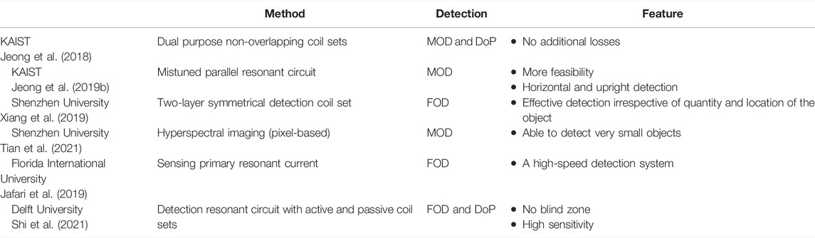
TABLE 9. Various real-time FOD methods.
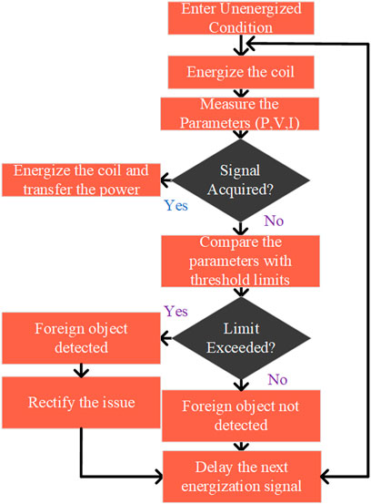
FIGURE 6. Flowchart for FOD.
Economic Aspects
A precise infrastructure installation for charging is mandatory to rush the market diffusion of the EV. The EV’s total operating cost includes the vehicle cost, energy consumption cost, and infrastructure development cost (Suh and Dong, 2017). So, the consideration of charging infrastructure is mandatory for effective cost analysis. The economic factors of energy consumption of OLEV with CNG were analyzed by KAIST. From the analysis, 73% of energy cost was saved by OLEV. The energy cost was analyzed by driving a vehicle for 250 km per day. In an electric vehicle, when the driving distance is increased, the saving cost will be increased. In 2009, KAIST has developed an online electric vehicle. The power drawn by the vehicle is 60 kW. Tables 10, 11 represent the cost of energy consumed by the vehicles. The distance covered by the vehicle was considered 13,286 km/yr. From the comparison, the infrastructure cost of the OLEV was 73% of the battery-operated vehicles (Suh et al., 2011).
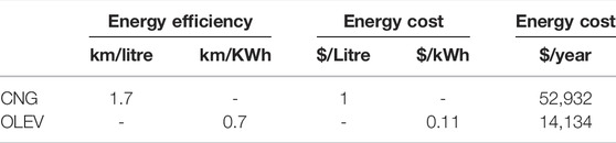
TABLE 10. Cost analysis of OLEV with CNG (Suh and Dong, 2017).

TABLE 11. Analysis for 10 years (Suh and Dong, 2017).
In Jeong et al. (2015), an economic model is proposed to analyze the advantageous effect of DWPT on the battery size reduction and life cycle improvement. Although the DWPT tracks installation cost is high compared with stationary WPT, the operational cost is low by extending the battery life and reducing the battery size. The three different WPT charging technologies such as stationary WPT (SWC), dynamic WPT (DWC), and quasi-dynamic WPT (QWC) are compared in Jang Y. et al. (2016). Table 12 represents the energy consumed by various electric vehicles and the reduction of cost with gasoline vehicles.
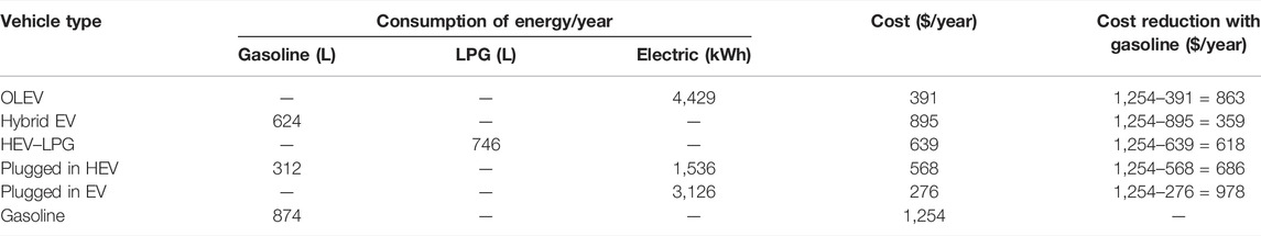
TABLE 12. Cost of energy consumed by vehicles (operational distance of the vehicle 13,286 km/yr) (Suh et al., 2011).
The sensitivity analysis of OLEV operated in Gumi City (Jeong et al., 2015) is represented in Figure 7. The advantages of extended battery life and low battery size are valid only for long-distance DWC. The social cost saving is achievable by a widespread DWPT by decarbonizing transportation (Lazzeroni et al., 2021). The energy consumption of the EVs is specified in Table 13 as per 2022 standards. In addition, the annual fuel cost was calculated, and the fuel-saving cost was compared with gas-powered vehicles. The cost of the fuel is taken as per the rate in 2022. As per NASA (2022), the emission of CO2 is 418 parts per million and the global temperature was increased by 1.01°C. So, many countries planned to reduce gasoline-based vehicle usage and encourage the usage of electric vehicles.
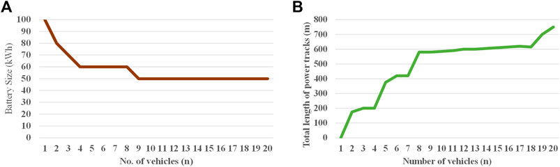
FIGURE 7. Sensitivity analysis by expanding the vehicle count (OLEV, Gumi City). (A) Number of vehicles vs. battery size. (B) Number of vehicles vs. total length of power tracks (Jeong et al., 2015).
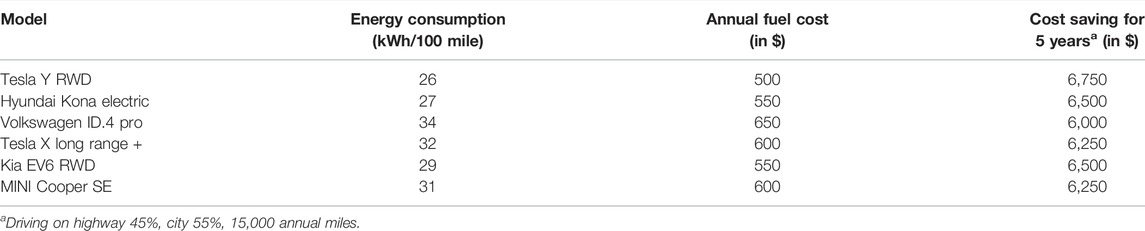
TABLE 13. Fuel cost comparison of few EV (fueleconomy.gov The official U.S. government Source, 2021).
EMC/EMI Issues
An electric vehicle charging based on dynamic inductive power transfer technology transfers a high power (in terms of kW) over a large distance (in terms of mm) in the air medium. The frequency level of the high power is 85 kHz. The high strength of the magnetic field will be generated by induced emf during this power transfer. So, the high-strength electric and magnetic fields will be produced around the system. In addition, the battery can finish charging the vehicle within a short period. The production of the high-field strength should not exceed the allowable safe limit. The safety limits were regulated by ICNIRP and IEEE and are mentioned in Table 5. Different shielding methods are used to diminish the leakage flux around the system.
The different types of shielding techniques (Houran et al., 2018) are passive shielding (magnetic, conductive, conductive, and magnetic), active shielding (EMF cancel (3-dB dominant, linkage-free, independent self)), and resonant reactive shielding (one shield coil with one capacitor, twoshield coils with four capacitors). The passive shielding techniques are based on materials used in the shielding process. Magnetic materials like ferrite, conductive material like aluminum, and metamaterials which are having combined characteristics are used in passive shielding. The EMF cancellation method is used in the active shielding technique. The cancellation of self-emf, cancelation of 3-dB dominant emf, and cancellation of linkage emf methods are the active shielding process. In reactive shielding, a different number of coils with capacitors will be used. The hazardous effects on health and improper function of the system components can be reduced by shielding methods (IEEE, 2019). The materials used in magnetic shielding control the exposure level and support the distribution of flux. The material will allow the magnetic flux through them due to its low reluctance properties.
The reluctance of the materials is directly proportional to the length of the coil (L), indirectly proportional to the cross-sectional area (A), and the permeability of the core materials. So, increasing the cross section of the pad will reduce the reluctance of the magnetic flux distribution path.
The reluctance of the material is,
The aluminum plate is an effective shielding material for the WPT3 class. The additional magnetic shielding is required for high power level than the WPT3 class. The strength of the magnetic field emission in identical charging coils is lesser than in coils with interoperability characteristics. The permeability of the different materials are 100–600 for nickel, 80,000–100,000 for Mu metal, and for aluminum is 1.000022. The ORNL researchers (Mohammad et al., 2021) investigated the requirements of shielding structures for charging pads. The ground assembly shielding is used to limit the distribution of magnetic fields beyond the shielding plate and the lateral side of the plate (Lammle et al., 2020). The proper shielding methods will ensure the limit of the human exposure level and satisfy the safety limits regulated by the ICNIRP. The various methods of EMI analysis are represented in Table 14.
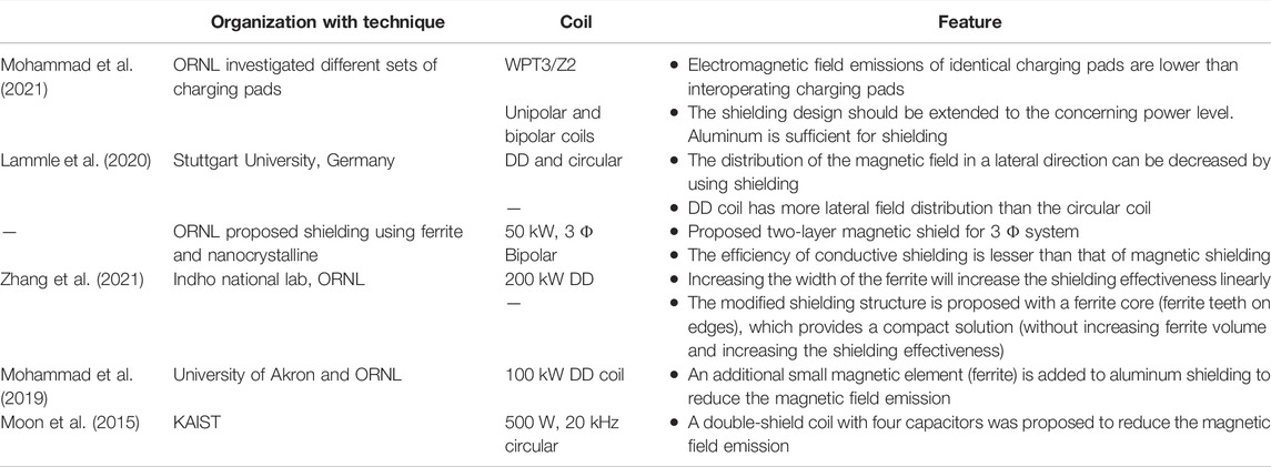
TABLE 14. Various EMI analysis.
Microgrid-Connected Dynamic Charging System
The development of charging infrastructures failed to meet the penetration of EV market evolution. The increases in EV charging stations will affect the public utility grid. The requirement for fossil fuels increased badly to compromise the energy demand raised by charging stations. The quantity of various conventional energy sources is decaying day by day. In addition, the temperature level of the world will increase due to greenhouse gases. Several countries are regulating their standards and aiming for net-zero emission in 2050. Renewable energy-based electricity production is increased by 3% in 2020, while the demand for all other fuels decreased (Dr Fatih Birol IEA Executive Director, 2021). Renewable energy sources will reduce the usage of fossil fuels. Decarbonization is achieved by encouraging the use of renewable energy sources throughout all sectors. The generation of electricity based on renewable sources around the world enormously increased in the past decade (International Renewable Energy Agency, 2021). The growth in PV-based energy generation decays the emission of greenhouse gases. So, integrating renewable energy sources with the EV-charging infrastructures will assist the development of road transport electrification. As a result of this integration, public charging sectors will grow and the unit per cost for energy consumption will decrease. The benefits of the PV-integrated charging stations are reduction of power quality issues in the power grid, cost savings, zero emission, easy installation, and supportive government policies. The microgrid system is mentioned in Figure 2.
In the European countries, the photovoltaic noise barriers (PVNB) are installed along roadsides, near railroads, and near industries. The rated power of the smallest installation is 7.5 kWp and the largest is 3 MWp. The major contributors of this technology are Germany, Italy, Switzerland, and the Netherlands (Pvresources, 2022). The first PVNB was built in Chur at Switzerland in the year of 1989 (de Jong, 2015). As a part of solar PV energy program, the MassDOT had installed 5.5 MW ground-mount PV arrays within ROW highway. The noise barriers proposed by them to explore the usage of renewable energy sources included barriers (Fhwa, 2017). A concept of e-road was proposed to harvest the roadside energy such as piezoelectric, thermoelectric, and solar energy (Pei et al., 2019). The roadside energy can be utilized by sensors, wireless charging, and melting snow and ice on the roads. The concept of solar road was proposed by the Brusaw couple and the pavement was developed on roadsides. The first solar road Wattway was constructed in France for 1 km long (Zhou B. et al., 2021). Therefore, many countries are developing their transportation infrastructure with solar integration. The integration of these energy sources will affect the parameters of the existing microgrid system. The development of green transportation will encourage the island grid system to integrate the roadway powered inductive power charging system. The main considerations of these solar based island microgrid systems are tolerable of sudden load changes, generation and utilization management, and fault tolerance.
The energy demand of the DWPT system significantly affects the distribution network and will disturb the power transfer profile of the microgrid system. The researchers under the FABRIC project (Theodoropoulos et al., 2014) analyzed the impact of the DWPT system on the grid. The intermittent segmental charging pad structure generates a high demand fluctuation in the grid system. In addition, they suggested that a smooth power transfer profile can be achieved by a continuous charging track, with an energy storage system and integration of PV power. The installation of the DWPT system in the existing grid (Debnath et al., 2018) will disturb the grid voltage, which leads to the reduction of reliability and power transfer profile and a rise in oscillatory response. In Karakitsios et al. (2016), a new methodology was implemented in a Greek MV distribution feeder realistic model to evaluate the theoretical and practical results to estimate the charging demand. The impact of an increase in demand on distribution line voltages, loads, and network losses was analyzed. During the particular period (t) in a day, the probability (P) of an on-road resonant inductive charging system supplying demand is the multiplication of the probability of a charging system occupied by needy EVs and occupied by EVs queuing on the pad due to road traffic.
In addition, when number of chargers, N is operating for a time period (t in hr) and maximum number of charging system installed in the grid is M, then
where tmax is the period where the observed maximum charging demand probability. The formulas are obtained from the case study of the primary transformer station with a single radial feeder at Katerini. In Zhou et al. (2022), the new microgrid structure was developed for cost saving and enlarge the usage of developed utility. The developed model includes solar, wind, and on-route charging system. An on-route charging system is considered as ESD in-motion state. The power transmission level between developed microgrid and main transmission grid is limited within certain level. An outage of power, coupling and decoupling of the RES occurring depends on that predefined level. As per these developed models, the output power of the RES is
where P and v represent the output power and speed of the wind turbine, respectively in t hour. P PC_WT represents planned capacity of the wind turbine. Then,
where At and Arated (1 kW/m2) represent the actual and rated light intensity at t hour, which is a desirable factor for PVs output, and PPC_solar is the planned capacity of PVs.
So, when the in-motion energy storage system considers EVs, the load difference in the grid system at t hour is
where NEV,I,t is the number of EVs on i road and (1—ZEV) is the proportionate value of EVs not involved in the DWC process, which establishes the movable load. An (Haupt et al., 2020) optimal capacity of the ESD determined by the developed mixed integer linear programming model. The developed model demonstrated in the A8 freeway at Germany.
Conclusion
This article mainly concentrates on exposure to microgrid-integrated DWPT technology. The different converters, coils, and compensation networks topologies in the design of DWPT-based charging infrastructure are presented comprehensively. The different compensation networks can be used based on applications such as load and coupling variations. In addition, the compensation network is used to resonate with the charging pads. The charging pads are designed based on the power level, the vertical distance of charging pads, and the speed of the charging vehicle. The design of charging pads is the most considerable section in the design of dynamic charging systems. The power inverters are used to drive the charging pads. The energization and de-energization of the charging pads are controlled by the power inverter. The power inverter generates the control signal as per SAE standards. The generation of a control signal is depending on the output of the detection circuit. It might be sensor-based or sensorless. The detection circuit is used to sense the interaction of the foreign object with charging pads and detect the vehicle’s position. The economic considerations involved in infrastructure development are compared and tabulated. The main objective of the designing process is to obtain maximum efficiency with reduced cost. The increase in the power level of the system to reduce the charging time indeed enlarges the magnetic emission exposure level. So, proper shielding is mandatory to decrease the field emission level. In addition to that, the standards involved in the design are also mentioned. The recent research and development work carried out in the DWPT system in various organizations are specified and tabulated. The microgrid-integrated DWPT system is also discussed in this article.
The organizations such as ORNL, KAIST, and Auckland University are developing a high-power dynamic charging system. ORNL is developing a 200-kW dynamic charging system to charge the vehicles quickly with highway power. This will encourage the usage of mini-trucks and buses in the public transportation system. The energy received while traveling on the charging lane should be greater than energy spent to cross that lane. The current research developments on a roadway powered charging system are integration of renewable energy sources such as solar and wind, developing a microgrid system for a dynamic charging infrastructure to reduce the impact on utility grid, limiting the emf exposure level, and fast charging with multiple users. The cost will decrease to the user when the number of vehicles using the dynamic charging system is increased.
Author Contributions
YS wrote the main manuscript text, figures, and tables. NR wrote the main manuscript text, figures, and tables. JS reviewed the manuscript and contributed in the power converter section of the manuscript. DA reviewed the manuscript and contributed in the microgrid section of the manuscript. All authors have contributed equally to the work.
Funding
This work was supported in part by the Government of India, Department of Science and Technology (DST), Science and Engineering Research Board (SERB), and the Core Research Grant CRG/2020/004073. This work was also supported by the Renewable Energy Lab, College of Engineering, Prince Sultan University, Riyadh, Saudi Arabia.
Conflict of Interest
The authors declare that the research was conducted in the absence of any commercial or financial relationships that could be construed as a potential conflict of interest.
Publisher’s Note
All claims expressed in this article are solely those of the authors and do not necessarily represent those of their affiliated organizations, or those of the publisher, the editors, and the reviewers. Any product that may be evaluated in this article, or claim that may be made by its manufacturer, is not guaranteed or endorsed by the publisher.
References
Abou Houran, M., Yang, X., and Chen, W. (2018). Magnetically Coupled Resonance Wpt: Review of Compensation Topologies, Resonator Structures with Misalignment, and Emi Diagnostics. Electronics 7, 296. doi:10.3390/electronics7110296
Ahmad, A., Alam, M. S., and Chabaan, R. (2018). A Comprehensive Review of Wireless Charging Technologies for Electric Vehicles. IEEE Trans. Transp. Electrific. 4, 38–63. doi:10.1109/TTE.2017.2771619
Ahmad, A., Alam, M. S., and Mohamed, A. A. S. (2019). Design and Interoperability Analysis of Quadruple Pad Structure for Electric Vehicle Wireless Charging Application. IEEE Trans. Transp. Electrific. 5, 934–945. doi:10.1109/TTE.2019.2929443
Ahmad, F., Saad Alam, M., Saad Alsaidan, I., and Shariff, S. M. (2020). Battery Swapping Station for Electric Vehicles: Opportunities and Challenges. IET Smart Grid 3, 280–286. doi:10.1049/iet-stg.2019.0059
Bagchi, A. C., Kamineni, A., Zane, R. A., and Carlson, R. (2021). Review and Comparative Analysis of Topologies and Control Methods in Dynamic Wireless Charging of Electric Vehicles. IEEE J. Emerg. Sel. Top. Power Electron. 9, 4947–4962. doi:10.1109/JESTPE.2021.3058968
Barsari, V. Z., Thrimawithana, D. J., and Covic, G. A. (2021). An Inductive Coupler Array for In-Motion Wireless Charging of Electric Vehicles. IEEE Trans. Power Electron. 36, 9854–9863. doi:10.1109/TPEL.2021.3058666
BombardierRail (2014). World’s First Electric Bus with Bombardier’s PRIMOVE System Begins Revenue Service. Available at: https://bombardier.com/en/media/news/worlds-first-electric-bus-bombardiers-primove-system-begins-revenue-service.
Bouanou, T., El Fadil, H., Lassioui, A., Assaddiki, O., and Njili, S. (2021). Analysis of Coil Parameters and Comparison of Circular, Rectangular, and Hexagonal Coils Used in Wpt System for Electric Vehicle Charging. Wevj 12, 45. doi:10.3390/wevj12010045
Budhia, M., Boys, J. T., Covic, G. A., and Huang, C.-Y. (2013). Development of a Single-Sided Flux Magnetic Coupler for Electric Vehicle IPT Charging Systems. IEEE Trans. Ind. Electron. 60, 318–328. doi:10.1109/TIE.2011.2179274
Buspress (2011). Application of Shaped Magnetic Field in Resonance (SMFIR) Technology to Future Urban Transportation. Available at: http://www.buspress.eu/wp-content/uploads/2013/08/CIRP-Design-2011-Paper34-Suh.pdf.
Chen, Y., Kou, Z., Zhang, Y., He, Z., Mai, R., and Cao, G. (2018). Hybrid Topology with Configurable Charge Current and Charge Voltage Output-Based WPT Charger for Massive Electric Bicycles. IEEE J. Emerg. Sel. Top. Power Electron. 6, 1581–1594. doi:10.1109/JESTPE.2017.2782269
Chen, Y., Zhang, H., Shin, C.-S., Jo, C.-H., Park, S.-J., and Kim, D.-H. (2020). An Efficiency Optimization-Based Asymmetric Tuning Method of Double-Sided LCC Compensated WPT System for Electric Vehicles. IEEE Trans. Power Electron. 35, 11475–11487. doi:10.1109/TPEL.2020.2984712
Cheng, B., Lu, J., Zhang, Y., Pan, G., Chabaan, R., and Mi, C. (2020a). A Metal Object Detection System with Multilayer Detection Coil Layouts for Electric Vehicle Wireless Charging. Energies 13, 2960. doi:10.3390/en13112960
Cheng, C., Lu, F., Zhou, Z., Li, W., Deng, Z., Li, F., et al. (2020b). A Load-independent LCC-Compensated Wireless Power Transfer System for Multiple Loads with a Compact Coupler Design. IEEE Trans. Ind. Electron. 67, 4507–4515. doi:10.1109/TIE.2019.2931260
Choi, S. Y., Gu, B. W., Jeong, S. Y., and Rim, C. T. (2015). Advances in Wireless Power Transfer Systems for Roadway-Powered Electric Vehicles. IEEE J. Emerg. Sel. Top. Power Electron. 3, 18–36. doi:10.1109/JESTPE.2014.2343674
Conductix (2022). Product Overview Inductive Power Transfer-IPT ®. Available at: https://www.conductix.com/sites/default/files/downloads/KAT9000-0001-E_Product_Overview_IPT.pdf (Accessed April 21, 2022).
Covic, G. A., Boys, J. T., Kissin, M. L. G., and Lu, H. G. (2007). A Three-phase Inductive Power Transfer System for Roadway-Powered Vehicles. IEEE Trans. Ind. Electron. 54, 3370–3378. doi:10.1109/TIE.2007.904025
Covic, G. A., and Boys, J. T. (2013). Modern Trends in Inductive Power Transfer for Transportation Applications. IEEE J. Emerg. Sel. Top. Power Electron. 1, 28–41. doi:10.1109/JESTPE.2013.2264473
de Jong, M. (2015). Solar Highways Benchmark Study an Overview and Evaluation of Existing Photovoltaic Noise Barriers. Available at: https://repository.tno.nl/islandora/object/uuid%3A9d0516be-0ca5-4dca-8260-43edd4f301ca.
de Marco, D., Dolara, A., Longo, M., and Yaïci, W. (2019). Design and Performance Analysis of Pads for Dynamic Wireless Charging of EVs Using the Finite Element Method. Energies 12, 4139. doi:10.3390/en12214139
Debnath, S., Foote, A., Onar, O. C., and Chinthavali, M. (2018). “Grid Impact Studies from Dynamic Wireless Charging in Smart Automated Highways,” in 2018 IEEE Transportation and Electrification Conference and Expo, ITEC 2018 (Long Beach, CA: Institute of Electrical and Electronics Engineers Inc.), 650–655. doi:10.1109/ITEC.2018.8450149
Deng, Q., Liu, J., Czarkowski, D., Hu, W., and Zhou, H. (2017). An Inductive Power Transfer System Supplied by a Multiphase Parallel Inverter. IEEE Trans. Ind. Electron. 64, 7039–7048. doi:10.1109/TIE.2017.2686351
Deng, Q., Sun, P., Hu, W., Czarkowski, D., Kazimierczuk, M. K., and Zhou, H. (2019a). Modular Parallel Multi-Inverter System for High-Power Inductive Power Transfer. IEEE Trans. Power Electron. 34, 9422–9434. doi:10.1109/TPEL.2019.2891064
Deng, Q., Wang, Z., Chen, C., Czarkowski, D., Kazimierczuk, M. K., Zhou, H., et al. (2019b). Modeling and Control of Inductive Power Transfer System Supplied by Multiphase Phase-Controlled Inverter. IEEE Trans. Power Electron. 34, 9303–9315. doi:10.1109/TPEL.2018.2886846
Department of Energy’s Oak Ridge National Laboratory (2018). ORNL Demonstrates 120-kilowatt Wireless Charging for Vehicles. Available at: https://www.ornl.gov/news/ornl-demonstrates-120-kilowatt-wireless-charging-vehicles#:∼:text=19%2C%202018%E2%80%94Researchers%20at%20the,a%20gas%20station%20fill%2Dup.
Department of Energy’s Oak Ridge National Laboratory (2016). ORNL Surges Forward with 20-kilowatt Wireless Charging for Vehicles. Available at: https://www.ornl.gov/news/ornl-surges-forward-20-kilowatt-wireless-charging-vehicles.
Dr Fatih Birol IEA Executive Director (2021). Global Energy Review 2021. Available at: https://www.iea.org/reports/global-energy-review-2021.
Eltis News Editor (2015). Wireless Charging for Quiet and Clean Public Transport in Torino (Italy). Available at: https://www.eltis.org/discover/case-studies/wireless-charging-quiet-and-clean-public-transport-torino-italy.
Farajizadeh, F., Vilathgamuwa, D. M., Jovanovic, D., Jayathurathnage, P., Ledwich, G., and Madawala, U. (2020). Expandable N-Legged Converter to Drive Closely Spaced Multitransmitter Wireless Power Transfer Systems for Dynamic Charging. IEEE Trans. Power Electron. 35, 3794–3806. doi:10.1109/TPEL.2019.2939848
Feng, H., Tavakoli, R., Onar, O. C., and Pantic, Z. (2020). Advances in High-Power Wireless Charging Systems: Overview and Design Considerations. IEEE Trans. Transp. Electrific. 6, 886–919. doi:10.1109/TTE.2020.3012543
Fhwa (2017). Highway Renewable Energy: Photovoltaic Noise Barriers. Available at: https://www.fhwa.dot.gov/environment/sustainability/energy/publications/photovoltaic/.
fueleconomy.gov The official U.S. government Source (2021). Fuel Economy of EVs. Available at: https://fueleconomy.gov/feg/PowerSearch.do?action=noformandpath=1andyear=2021andmclass=Sport%20Utility%20Vehiclesandsrchtyp=marClassMpgandpageno=1androwLimit=50.
Fujita, T., Yasuda, T., and Akagi, H. (2017). A Dynamic Wireless Power Transfer System Applicable to a Stationary System. IEEE Trans. Ind. Appl. 53, 3748–3757. doi:10.1109/TIA.2017.2680400
Ge, X.-J., Sun, Y., Wang, Z.-H., and Tangsen, C.-S. (2019). Dual-Independent-Output Inverter for Dynamic Wireless Power Transfer System. IEEE Access 7, 107320–107333. doi:10.1109/ACCESS.2019.2933017
Gonzalez-Santini, N. S., Zeng, H., Yu, Y., and Peng, F. Z. (2016). Z-source Resonant Converter with Power Factor Correction for Wireless Power Transfer Applications. IEEE Trans. Power Electron. 31, 7691–7700. doi:10.1109/TPEL.2016.2560174
Graeme Davison Vice President, T. (2017). From Wireless to Dynamic Electric Vehicle Charging: The Evolution of Qualcomm Halo [video]. Available at: https://www.qualcomm.com/news/onq/2017/05/18/wireless-dynamic-ev-charging-evolution-qualcomm-halo.
Guo, Y., Wang, L., Zhu, Q., Liao, C., and Li, F. (2016). Switch-On Modeling and Analysis of Dynamic Wireless Charging System Used for Electric Vehicles. IEEE Trans. Ind. Electron. 63, 6568–6579. doi:10.1109/TIE.2016.2557302
Haupt, L., Schöpf, M., Wederhake, L., and Weibelzahl, M. (2020). The Influence of Electric Vehicle Charging Strategies on the Sizing of Electrical Energy Storage Systems in Charging Hub Microgrids. Appl. Energy 273, 115231. doi:10.1016/j.apenergy.2020.115231
HEVO (2021). HEVO: Wireless Charging for Electric Vehicles. Available at: https://hevo.com/rezonant-e8.html#transmitter2 (Accessed May 24, 2022).
Hossain, A., Darvish, P., Mekhilef, S., Tey, K. S., and Tong, C. W. (2022). A New Coil Structure of Dual Transmitters and Dual Receivers with Integrated Decoupling Coils for Increasing Power Transfer and Misalignment Tolerance of Wireless EV Charging System. IEEE Trans. Ind. Electron. 69, 7869–7878. doi:10.1109/TIE.2021.3108697
Hsieh, Y.-C., Chu, C.-W., Chang, H.-W., and Lin, C.-Y. (2021). Inductive Power Transfer Converter with Center-Tapped Pickup Winding. IEEE Trans. Power Electron. 36, 12432–12439. doi:10.1109/TPEL.2021.3081598
Hwansoo Moon, H., Sungkyu Kim, S., Hyun Ho Park, H. H., and Seungyoung Ahn, S. (2015). Design of a Resonant Reactive Shield with Double Coils and a Phase Shifter for Wireless Charging of Electric Vehicles. IEEE Trans. Magn. 51, 1–4. doi:10.1109/TMAG.2014.2360701
IEEE (2019). “Institute of Electrical and Electronics Engineers, and IEEE Electromagnetic Compatibility Society,” in 2019 IEEE International Symposium on Electromagnetic Compatibility, Signal Integrity and Power Integrity (IEEE).
International Renewable Energy Agency (2021). Renewable Energy Statistics 2021 Statistiques D’énergie Renouvelable 2021 Estadísticas De Energía Renovable 2021 about Irena. Available at: www.irena.org.
INTIS (2018). INTIS Engineering for the Future INTIS Projects. Available at: https://intis.de/wireless-power-transfer.html#projects.
IPT Technology (2021). Dynamic Wireless Charging of Electric Vehicles in Motion. Available at: https://ipt-technology.com/e-mobility-wireless-dynamic-charging/.
Jafari, H., Moghaddami, M., and Sarwat, A. I. (2019). Foreign Object Detection in Inductive Charging Systems Based on Primary Side Measurements. IEEE Trans. Ind. Appl. 55, 6466–6475. doi:10.1109/TIA.2019.2937501
Jafari, H., Olowu, T. O., Mahmoudi, M., and Sarwat, A. (2021). Optimal Design of IPT Bipolar Power Pad for Roadway-Powered EV Charging Systems. IEEE Can. J. Electr. Comput. Eng. 44, 350–355. doi:10.1109/icjece.2021.3075639
Jang, G. C., Jeong, S. Y., Kwak, H. G., and Rim, C. T. (2016a). “Metal Object Detection Circuit with Non-overlapped Coils for Wireless EV Chargers,” in 2016 IEEE 2nd Annual Southern Power Electronics Conference, SPEC 2016 (Auckland, New Zealand: Institute of Electrical and Electronics Engineers Inc.). doi:10.1109/SPEC.2016.7846132
Jang, Y., Jeong, S., and Lee, M. (2016b). Initial Energy Logistics Cost Analysis for Stationary, Quasi-Dynamic, and Dynamic Wireless Charging Public Transportation Systems. Energies 9, 483. doi:10.3390/en9070483
Jayalath, S., and Khan, A. (2021). Design, Challenges, and Trends of Inductive Power Transfer Couplers for Electric Vehicles: A Review. IEEE J. Emerg. Sel. Top. Power Electron. 9, 6196–6218. doi:10.1109/JESTPE.2020.3042625
Jeong, S., Jang, Y. J., and Kum, D. (2015). Economic Analysis of the Dynamic Charging Electric Vehicle. IEEE Trans. Power Electron. 30, 6368–6377. doi:10.1109/TPEL.2015.2424712
Jeong, S., Jang, Y. J., Kum, D., and Lee, M. S. (2019a). Charging Automation for Electric Vehicles: Is a Smaller Battery Good for the Wireless Charging Electric Vehicles? IEEE Trans. Autom. Sci. Eng. 16, 486–497. doi:10.1109/TASE.2018.2827954
Jeong, S. Y., Kwak, H. G., Jang, G. C., Choi, S. Y., and Rim, C. T. (2018). Dual-Purpose Nonoverlapping Coil Sets as Metal Object and Vehicle Position Detections for Wireless Stationary EV Chargers. IEEE Trans. Power Electron. 33, 7387–7397. doi:10.1109/TPEL.2017.2765521
Jeong, S. Y., Thai, V. X., Park, J. H., and Rim, C. T. (2019b). Self-Inductance-Based Metal Object Detection with Mistuned Resonant Circuits and Nullifying Induced Voltage for Wireless EV Chargers. IEEE Trans. Power Electron. 34, 748–758. doi:10.1109/TPEL.2018.2813437
Kalra, G. R., Riar, B. S., and Thrimawithana, D. J. (2020). An Integrated Boost Active Bridge Based Secondary Inductive Power Transfer Converter. IEEE Trans. Power Electron. 35, 12716–12727. doi:10.1109/TPEL.2020.2984784
Karakitsios, I., Karfopoulos, E., and Hatziargyriou, N. (2016). Impact of Dynamic and Static Fast Inductive Charging of Electric Vehicles on the Distribution Network. Electr. Power Syst. Res. 140, 107–115. doi:10.1016/j.epsr.2016.06.034
Keeling, N. A., Covic, G. A., and Boys, J. T. (2010). A Unity-Power-Factor IPT Pickup for High-Power Applications. IEEE Trans. Ind. Electron. 57, 744–751. doi:10.1109/TIE.2009.2027255
Kim, J. H., Lee, B.-S., Lee, J.-H., Lee, S.-H., Park, C.-B., Jung, S.-M., et al. (2015). Development of 1-MW Inductive Power Transfer System for a High-Speed Train. IEEE Trans. Ind. Electron. 62, 6242–6250. doi:10.1109/TIE.2015.2417122
Kim, S., Choi, W., and Lim, Y. (2021). Metal Object Detection in a Wireless High-Power Transfer System Using Phase–Magnitude Variation. Electron. Switz. 10. doi:10.3390/electronics10232952
Kim, S., Covic, G. A., and Boys, J. T. (2017). Tripolar Pad for Inductive Power Transfer Systems for EV Charging. IEEE Trans. Power Electron. 32, 5045–5057. doi:10.1109/TPEL.2016.2606893
Kissin, M. L. G., Boys, J. T., and Covic, G. A. (2009). Interphase Mutual Inductance in Polyphase Inductive Power Transfer Systems. IEEE Trans. Ind. Electron. 56, 2393–2400. doi:10.1109/TIE.2009.2020076
Lammle, T., Parspour, N., and Monch, M. (2020). “Analysis of the Magnetic Field Distribution in Inductive Power Transfer Systems under the Influence of Aluminum Shielding,” in 2020 5th International Conference on Smart and Sustainable Technologies, SpliTech 2020 (Split, Croatia: Institute of Electrical and Electronics Engineers Inc.). doi:10.23919/SpliTech49282.2020.9243851
Laporte, S., Coquery, G., Deniau, V., de Bernardinis, A., and Hautière, N. (2019). Dynamic Wireless Power Transfer Charging Infrastructure for Future EVs: From Experimental Track to Real Circulated Roads Demonstrations. Wevj 10, 84. doi:10.3390/wevj10040084
Lazzeroni, P., Cirimele, V., and Canova, A. (2021). Economic and Environmental Sustainability of Dynamic Wireless Power Transfer for Electric Vehicles Supporting Reduction of Local Air Pollutant Emissions. Renew. Sustain. Energy Rev. 138, 110537. doi:10.1016/j.rser.2020.110537
Lee, E. S., Kim, M. Y., Kang, S. M., and Han, S. H. (2022). Segmented IPT Coil Design for Continuous Multiple Charging of an Electrified Monorail System. IEEE Trans. Power Electron. 37, 3636–3649. doi:10.1109/TPEL.2021.3115511
Li, S., Li, W., Deng, J., Nguyen, T. D., and Mi, C. C. (2015). A Double-Sided LCC Compensation Network and its Tuning Method for Wireless Power Transfer. IEEE Trans. Veh. Technol. 64, 2261–2273. doi:10.1109/TVT.2014.2347006
Li, Y., Mai, R., Lu, L., Lin, T., Liu, Y., and He, Z. (2018). Analysis and Transmitter Currents Decomposition Based Control for Multiple Overlapped Transmitters Based WPT Systems Considering Cross Couplings. IEEE Trans. Power Electron. 33, 1829–1842. doi:10.1109/TPEL.2017.2690061
Lin, F., Covic, G. A., and Kesler, M. (2020). Design of a SAE Compliant Multicoil Ground Assembly. IEEE J. Emerg. Sel. Top. Ind. Electron. 1, 14–25. doi:10.1109/jestie.2020.2999597
Lin, F. Y., Covic, G. A., and Boys, J. T. (2015). Evaluation of Magnetic Pad Sizes and Topologies for Electric Vehicle Charging. IEEE Trans. Power Electron. 30, 6391–6407. doi:10.1109/TPEL.2015.2419592
Liu, J., Xu, W., Chan, K. W., Liu, M., Zhang, X., and Chan, N. H. L. (2020). A Three-phase Single-Stage AC-DC Wireless-Power-Transfer Converter with Power Factor Correction and Bus Voltage Control. IEEE J. Emerg. Sel. Top. Power Electron. 8, 1782–1800. doi:10.1109/JESTPE.2019.2916258
Lu, J., Zhu, G., and Mi, C. C. (2022). Foreign Object Detection in Wireless Power Transfer Systems. IEEE Trans. Ind. Appl. 58, 1340–1354. doi:10.1109/TIA.2021.3057603
Lu, J., Zhu, G., Wang, H., Lu, F., Jiang, J., and Mi, C. C. (2019). Sensitivity Analysis of Inductive Power Transfer Systems with Voltage-Fed Compensation Topologies. IEEE Trans. Veh. Technol. 68, 4502–4513. doi:10.1109/TVT.2019.2903565
Lumen Freedom. (2022). Leading the ChargeTM Lumen Freedom Announces the Supply of Wireless Charging Systems for the Wireless Charging of Electric Taxis (WiCET) Demonstration Project. Available at: https://lumenfreedom.com/lumen-freedom-announces-the-supply-of-wireless-charging-systems-for-the-wireless-charging-of-electric-taxis-wicet-demonstration-project/#.
Luo, Z., and Wei, X. (2018). Analysis of Square and Circular Planar Spiral Coils in Wireless Power Transfer System for Electric Vehicles. IEEE Trans. Ind. Electron. 65 (1), 331–341. doi:10.1109/TIE.2017.2723867
Luo, Z., Zhao, Y., Xiong, M., Wei, X., and Dai, H. (2022). A Self-Tuning LCC/LCC System Based on Switch-Controlled Capacitors for Constant-Power Wireless Electric Vehicle Charging. IEEE Trans. Ind. Electron. 1, 1. doi:10.1109/TIE.2022.3153812
Mahesh, A., Chokkalingam, B., and Mihet-Popa, L. (2021). Inductive Wireless Power Transfer Charging for Electric Vehicles-A Review. IEEE Access 9, 137667–137713. doi:10.1109/ACCESS.2021.3116678
Mai, R., Chen, Y., Li, Y., Zhang, Y., Cao, G., and He, Z. (2017). Inductive Power Transfer for Massive Electric Bicycles Charging Based on Hybrid Topology Switching with a Single Inverter. IEEE Trans. Power Electron. 32, 5897–5906. doi:10.1109/TPEL.2017.2654360
Matsumoto, H., Shibako, Y., Shiihara, Y., Nagata, R., and Neba, Y. (2018). Three-Phase Lines to Single-phase Coil Planar Contactless Power Transformer. IEEE Trans. Ind. Electron. 65, 2904–2914. doi:10.1109/TIE.2017.2748049
Miller, J. M., Jones, P. T., Li, J.-M., and Onar, O. C. (2015). ORNL Experience and Challenges Facing Dynamic Wireless Power Charging of EV's. IEEE Circuits Syst. Mag. 15, 40–53. doi:10.1109/MCAS.2015.2419012
Mishima, T., and Morita, E. (2017). High-Frequency Bridgeless Rectifier Based ZVS Multiresonant Converter for Inductive Power Transfer Featuring High-Voltage GaN-HFET. IEEE Trans. Ind. Electron. 64, 9155–9164. doi:10.1109/TIE.2017.2736482
Mishra, S., Verma, S., Chowdhury, S., Gaur, A., Mohapatra, S., Dwivedi, G., et al. (2021). A Comprehensive Review on Developments in Electric Vehicle Charging Station Infrastructure and Present Scenario of India. Sustainability 13 (4), 2396–2420. doi:10.3390/su13042396
Mohamed, A. A. S., An, S., and Mohammed, O. (2018). Coil Design Optimization of Power Pad in IPT System for Electric Vehicle Applications. IEEE Trans. Magn. 54, 1–5. doi:10.1109/TMAG.2017.2784381
Mohamed, A. A. S., Shaier, A. A., Metwally, H., and Selem, S. I. (2020a). A Comprehensive Overview of Inductive Pad in Electric Vehicles Stationary Charging. Appl. Energy 262, 114584. doi:10.1016/j.apenergy.2020.114584
Mohamed, A. A. S., Shaier, A. A., Metwally, H., and Selem, S. I. (2020b). Interoperability of the Universal WPT3 Transmitter with Different Receivers for Electric Vehicle Inductive Charger. eTransportation 6, 100084. doi:10.1016/j.etran.2020.100084
Mohammad, M., Onar, O. C., Pries, J. L., Galigekere, V. P., Su, G.-J., and Wilkins, J. (2021). “Analysis of Magnetic Field Emissions and Shield Requirements for Interoperating High-Power EV Wireless Charging System,” in Conference Proceedings - IEEE Applied Power Electronics Conference and Exposition - APEC (Phoenix, AZ: Institute of Electrical and Electronics Engineers Inc.), 1586–1592. doi:10.1109/APEC42165.2021.9487265
Mohammad, M., Pries, J., Onar, O., Galigekere, V. P., Su, G.-J., Anwar, S., et al. (2019). Design of an EMF Suppressing Magnetic Shield for a 100-kW DD-Coil Wireless Charging System for Electric Vehicles; Design of an EMF Suppressing Magnetic Shield for a 100-kW DD-Coil Wireless Charging System for Electric Vehicles. Available at: http://energy.gov/downloads/doe-public-access-plan.
NASA (2022). NASA Global Climate Change-Vital Signs of the Planet. Available at: https://climate.nasa.gov/.
Nguyen, V.-T., Van, B., Vu, G., and Fahimi, B. (2022). Coil-to-Coil Efficiency Optimization of Double-Sided LCC Topology for Electric Vehicle Inductive Chargers. IEEE Trans. Ind. Electron. 69, 11242–11252. doi:10.1109/TIE.2021.3118343
Panchal, C., Stegen, S., and Lu, J. (2018). Review of Static and Dynamic Wireless Electric Vehicle Charging System. Eng. Sci. Technol. Int. J. 21, 922–937. doi:10.1016/j.jestch.2018.06.015
Patents (2022). Apparatus, System, and Method for Detecting a Foreign Object in an Inductive Wireless Power Transfer System Based on Input Power. Available at: https://patents.google.com/patent/US9553485.
Patil, D., McDonough, M. K., Miller, J. M., Fahimi, B., and Balsara, P. T. (2018). Wireless Power Transfer for Vehicular Applications: Overview and Challenges. IEEE Trans. Transp. Electrific. 4, 3–37. doi:10.1109/TTE.2017.2780627
Pei, J., Zhou, B., and Lyu, L. (2019). E-Road: The Largest Energy Supply of the Future? Appl. Energy 241, 174–183. doi:10.1016/j.apenergy.2019.03.033
Pvresources (2022). Photovoltaic Noise Barriers. Available at: https://www.pvresources.com/en/pvpowerplants/noisebarriers.php (Accessed May 24, 2022).
SAE International (2020). Wireless Power Transfer for Light-Duty Plug-in/Electric Vehicles and Alignment Methodology J2954_202010. United States: SAE International.
Sanken Electric Co., Ltd (2022). Part 1. Compound Semiconductors: What Are SiC and GaN? Available at: https://www.semicon.sanken-ele.co.jp/en/guide/GaNSiC.html.
Shevchenko, V., Husev, O., Strzelecki, R., Pakhaliuk, B., Poliakov, N., and Strzelecka, N. (2019). Compensation Topologies in IPT Systems: Standards, Requirements, Classification, Analysis, Comparison and Application. IEEE Access 7, 120559–120580. doi:10.1109/ACCESS.2019.2937891
Shi, L., Delgado, A., Ramos, R., and Alou, P. (2022). A Wireless Power Transfer System with Inverse Coupled Current Doubler Rectifier for High-Output Current Applications. IEEE Trans. Ind. Electron. 69, 4607–4616. doi:10.1109/TIE.2021.3078350
Shi, W., Dong, J., Soeiro, T. B., and Bauer, P. (2021). Integrated Solution for Electric Vehicle and Foreign Object Detection in the Application of Dynamic Inductive Power Transfer. IEEE Trans. Veh. Technol. 70, 11365–11377. doi:10.1109/TVT.2021.3112278
Shladover, S. E. (1992). Highway Electrification and Automation. Available at: https://escholarship.org/uc/item/8kk9d7f7.
Sohn, Y. H., Choi, B. H., Lee, E. S., Lim, G. C., Cho, G.-H., and Rim, C. T. (2015). General Unified Analyses of Two-Capacitor Inductive Power Transfer Systems: Equivalence of Current-Source SS and SP Compensations. IEEE Trans. Power Electron. 30, 6030–6045. doi:10.1109/TPEL.2015.2409734
Song, K., Yang, G., Guo, Y., Lan, Y., Dong, S., Jiang, J., et al. (2020). Design of DD Coil with High Misalignment Tolerance and Low EMF Emissions for Wireless Electric Vehicle Charging Systems. IEEE Trans. Power Electron. 35, 9034–9045. doi:10.1109/TPEL.2020.2971967
Stellantis (2021). “Arena del Futuro”, Innovative Dynamic Induction Charging Becomes a Reality. Available at: https://www.stellantis.com/en/news/press-releases/2021/december/arena-del-futuro-innovative-dynamic-induction-charging-becomes-a-reality.
Suh, N. P., Cho, D. H., and Rim, C. T. (2011). “Design of On-Line Electric Vehicle (OLEV),” in Global Product Development - Proceedings of the 20th CIRP Design Conference (Nantes, France: Springer Science and Business Media Deutschland GmbH), 3–8. doi:10.1007/978-3-642-15973-2_1
Sullivan, C. R. (2001). Cost-constrained Selection of Strand Diameter and Number in a Litz-Wire Transformer Winding. IEEE Trans. Power Electron. 16, 281–288. doi:10.1109/63.911153
Sullivan, C. R. (1999). Optimal Choice for Number of Strands in a Litz-Wire Transformer Winding. IEEE Trans. Power Electron. 14, 283–291. doi:10.1109/63.750181
Tavakoli, R., and Pantic, Z. (2018). Analysis, Design, and Demonstration of a 25-kW Dynamic Wireless Charging System for Roadway Electric Vehicles. IEEE J. Emerg. Sel. Top. Power Electron. 6, 1378–1393. doi:10.1109/JESTPE.2017.2761763
The Paris Agreement (2022). UNFCCC. Available at: https://unfccc.int/process-and-meetings/the-paris-agreement/the-paris-agreement (Accessed April 19, 2022).
Theodoropoulos, T., Amditis, A., Sallan, J., Bludszuweit, H., Berseneff, B., Guglielmi, P., et al. (2014). “Impact of Dynamic EV Wireless Charging on the Grid,” in 2014 IEEE International Electric Vehicle Conference, IEVC 2014 (Florence, Italy: Institute of Electrical and Electronics Engineers Inc.). doi:10.1109/IEVC.2014.7056234
Tian, Y., Li, Z., Lin, Y., Xiang, L., Li, X., Shao, Y., et al. (2021). Metal Object Detection for Electric Vehicle Inductive Power Transfer Systems Based on Hyperspectral Imaging. Measurement 168, 108493. doi:10.1016/j.measurement.2020.108493
Triviño-Cabrera, A., González-González, J. M., and Aguado, J. A. (2020). Wireless Power Transfer for Electric Vehicles: Foundations and Design Approach. Available at: http://www.springer.com/series/4622.
Unplugged (2015). Final Report Project Acronym and Number: UNPLUGGED Project Number 314 126. Available at: www.unplugged-project.eu.
Utah State University Science and Technology (2012). Utah State University Unveils Wirelessly Charged Electric Bus. Available at: https://www.usu.edu/today/story/utah-state-university-unveils-wirelessly-charged-electric-bus.
Vaidya, B., and Mouftah, H. T. (2020). Dynamic Wireless Charging for CAEV Taxi Fleet in Urban Environment. Internet Technol. Lett. 3. doi:10.1002/itl2.153
Villa, J. L., Sallan, J., Sanz Osorio, J. F., and Llombart, A. (2012). High-misalignment Tolerant Compensation Topology for ICPT Systems. IEEE Trans. Ind. Electron. 59, 945–951. doi:10.1109/TIE.2011.2161055
Vu, V.-B., Phan, V.-T., Dahidah, M., and Pickert, V. (2019). Multiple Output Inductive Charger for Electric Vehicles. IEEE Trans. Power Electron. 34, 7350–7368. doi:10.1109/TPEL.2018.2882945
Wang, C., Zhu, C., Wei, G., Feng, J., Jiang, J., and Lu, R. (2020). Design of Compact Three-phase Receiver for Meander-type Dynamic Wireless Power Transfer System. IEEE Trans. Power Electron. 35, 6854–6866. doi:10.1109/TPEL.2019.2955203
Wang, W. V., and Thrimawithana, D. J. (2020). A Novel Converter Topology for a Primary-Side Controlled Wireless EV Charger with a Wide Operation Range. IEEE J. Emerg. Sel. Top. Ind. Electron. 1, 36–45. doi:10.1109/jestie.2020.3003357
Wang, X., Xu, J., Lu, S., Ren, S., Leng, M., and Ma, H. (2022). Single-receiver Multioutput Inductive Power Transfer System with Independent Regulation and Unity Power Factor. IEEE Trans. Power Electron. 37, 1159–1171. doi:10.1109/TPEL.2021.3100055
Wang, X., Xu, J., Mao, M., and Ma, H. (2021). An LCL-Based SS Compensated WPT Converter with Wide ZVS Range and Integrated Coil Structure. IEEE Trans. Ind. Electron. 68, 4882–4893. doi:10.1109/TIE.2020.2989707
Wang, Z., Wei, X., and Dai, H. (2016). Design and Control of a 3 kW Wireless Power Transfer System for Electric Vehicles. Energies 9, 10. doi:10.3390/en9010010
WiCET (2021). Wireless Charging of Electric Taxis (WiCET) WiCET Objectives. Available at: https://wicet.co.uk/2021/04/20/wicet-objectives/.
WiTricity (2022). WiTricity Is Accelerating the Adoption of EVs by Simplifying and Streamlining the Charging Experience. Available at: https://witricity.com/products/automotive/.
Xiang, L., Zhu, Z., Tian, J., and Tian, Y. (2019). Foreign Object Detection in a Wireless Power Transfer System Using Symmetrical Coil Sets. IEEE Access 7, 44622–44631. doi:10.1109/ACCESS.2019.2908866
Xiong, M., Wei, X., Huang, Y., Luo, Z., and Dai, H. (2021). Research on Novel Flexible High-Saturation Nanocrystalline Cores for Wireless Charging Systems of Electric Vehicles. IEEE Trans. Ind. Electron. 68 (9), 8310–8320. doi:10.1109/TIE.2020.3016259
Xue, M., Yang, Q., Zhu, G., and Li, L. (2022). A Position Detection Method for Dynamic Wireless Inspection Robots Charging. J. Electr. Eng. Technol. 17, 97–110. doi:10.1007/s42835-021-00864-9
Yang, G., Song, K., Huang, X., Wang, C., Huang, X., Li, J., et al. (2021a). Improved Interoperability Evaluation Method for Wireless Charging Systems Based on Interface Impedance. IEEE Trans. Power Electron. 36, 8588–8592. doi:10.1109/TPEL.2021.3053353
Yang, G., Song, K., Sun, Y., Huang, X., Li, J., Guo, Y., et al. (2021b). Interoperability Improvement for Rectangular Pad and DD Pad of Wireless Electric Vehicle Charging System Based on Adaptive Position Adjustment. IEEE Trans. Ind. Appl. 57, 2613–2624. doi:10.1109/TIA.2021.3056639
Yang, J., Zhang, X., Zhang, K., Cui, X., Jiao, C., and Yang, X. (2020). An LCC-SP Compensated Inductive Power Transfer System and Design Considerations for Enhancing Misalignment Tolerance. IEEE Access 8, 193285–193296. doi:10.1109/ACCESS.2020.3032793
Yilmaz, M., and Krein, P. T. (2013). Review of Battery Charger Topologies, Charging Power Levels, and Infrastructure for Plug-In Electric and Hybrid Vehicles. IEEE Trans. Power Electron. 28, 2151–2169. doi:10.1109/TPEL.2012.2212917
Zaheer, A., Hao, H., Covic, G. A., and Kacprzak, D. (2015). Investigation of Multiple Decoupled Coil Primary Pad Topologies in Lumped IPT Systems for Interoperable Electric Vehicle Charging. IEEE Trans. Power Electron. 30, 1937–1955. doi:10.1109/TPEL.2014.2329693
Zhang, B., Carlson, R. B., Galigekere, V. P., Onar, O. C., Mohammad, M., Dickerson, C. C., et al. (2021). “Quasi-dynamic Electromagnetic Field Safety Analysis and Mitigation for High-Power Dynamic Wireless Charging of Electric Vehicles,” in 2021 IEEE Transportation Electrification Conference and Expo, ITEC 2021 (Chicago, IL: Institute of Electrical and Electronics Engineers Inc.), 771–775. doi:10.1109/ITEC51675.2021.9490192
Zhang, W., and Mi, C. C. (2016). Compensation Topologies of High-Power Wireless Power Transfer Systems. IEEE Trans. Veh. Technol. 65, 4768–4778. doi:10.1109/TVT.2015.2454292
Zhang, W., White, J. C., Abraham, A. M., and Mi, C. C. (2015). Loosely Coupled Transformer Structure and Interoperability Study for EV Wireless Charging Systems. IEEE Trans. Power Electron. 30, 6356–6367. doi:10.1109/TPEL.2015.2433678
Zhang, Y., Yan, Z., Liang, Z., Li, S., and Mi, C. C. (2020). A High-Power Wireless Charging System Using LCL-N Topology to Achieve a Compact and Low-Cost Receiver. IEEE Trans. Power Electron. 35, 131–137. doi:10.1109/TPEL.2019.2914363
Zhang, Y., Yan, Z., Zhu, J., Li, S., and Mi, C. (2019). A Review of Foreign Object Detection (FOD) for Inductive Power Transfer Systems. eTransportation 1, 100002. doi:10.1016/j.etran.2019.04.002
Zhou, B., Pei, J., Calautit, J. K., Zhang, J., and Guo, F. (2021). Solar Self-Powered Wireless Charging Pavement-A Review on Photovoltaic Pavement and Wireless Charging for Electric Vehicles. Sustain. Energy Fuels 5, 5139–5159. doi:10.1039/d1se00739d
Zhou, H., Chen, J., Deng, Q., Chen, F., Zhu, A., Hu, W., et al. (2021). Input-Series Output-Equivalent-Parallel Multi-Inverter System for High-Voltage and High-Power Wireless Power Transfer. IEEE Trans. Power Electron. 36, 228–238. doi:10.1109/TPEL.2020.3000244
Zhou, Z., Liu, Z., Su, H., and Zhang, L. (2022). Bi-level Framework for Microgrid Capacity Planning under Dynamic Wireless Charging of Electric Vehicles. Int. J. Electr. Power & Energy Syst. 141, 108204. doi:10.1016/j.ijepes.2022.108204
Zhu, A., Zhou, H., Deng, Q., Shao, Y., Chen, J., Hu, W., et al. (2021). Modeling and Phase Synchronization Control of High-Power Wireless Power Transfer System Supplied by Modular Parallel Multi-Inverters. IEEE Trans. Veh. Technol. 70, 6450–6462. doi:10.1109/TVT.2021.3080515
Zhu, X., Zhao, X., Li, Y., Liu, S., Yang, H., Tian, J., et al. (2021). High-Efficiency WPT System for CC/CV Charging Based on Double-Half-Bridge Inverter Topology with Variable Inductors. IEEE Trans. Power Electron. 37, 1. doi:10.1109/TPEL.2021.3107461
Keywords: inverter, multilevel inverter, microgrid, inductive coupling, wireless charging and storage
Citation: S Y, R N, Sathik Mohamed Ali J and Almakhles D (2022) A Comprehensive Review of the On-Road Wireless Charging System for E-Mobility Applications. Front. Energy Res. 10:926270. doi: 10.3389/fenrg.2022.926270
Received: 22 April 2022; Accepted: 09 June 2022;
Published: 07 July 2022.
Edited by:
Sudhakar Babu Thanikanti, Chaitanya Bharathi Institute of Technology, IndiaReviewed by:
Haifeng Dai, Tongji University, ChinaDattatraya Gaonkar, National Institute of Technology, India
Nisha K. S, National Institute of Technology, India
Copyright © 2022 S, R, Sathik Mohamed Ali and Almakhles. This is an open-access article distributed under the terms of the Creative Commons Attribution License (CC BY). The use, distribution or reproduction in other forums is permitted, provided the original author(s) and the copyright owner(s) are credited and that the original publication in this journal is cited, in accordance with accepted academic practice. No use, distribution or reproduction is permitted which does not comply with these terms.
*Correspondence: Narayanamoorthi R, bmFyYXlhbmFtb29ydGhpLnJAZ21haWwuY29t; Dhafer Almakhles, ZGFsbWFraGxlc0Bwc3UuZWR1LnNh