 Wencheng Yang1
 Xuegang Xie
- 1Lincang Bureau, Yunnan Power Grid Co., Ltd., Lincang, China
- 2Yunnan Electric Power Technology Co., Ltd., Kunming, China
In order to improve the ability of fluxgate current sensor to detect weak residual current, starting from the magnetic ring, which is the key magnetic concentrating element, and adopting the method of Comsol simulation analysis, the open-loop fluxgate is introduced from the aspects of magnetic ring material selection and structural design, etc. The key technology of the design of the magnetic concentrating ring of the current sensor is verified by experiments that the magnetic ring can increase the sensitivity of the current measurement by 15.4 times, and the frequency can reach 6.7 kHz, which can meet the AC and DC complex leakage current detection. Provide technical reference for designers engaged in this type of sensor.
1 Introduction
Due to the continuous increase of DC equipment such as photovoltaic power generation, new energy vehicles, and DC charging piles, the residual current generated contains various DC components and is becoming more and more complex. In order to solve the problem of residual current detection containing DC signal, it is more important to realize the effective detection and leakage protection of AC and DC residual current (Young et al., 2007). Literature (Takahiro and Dev, 2011) proposed a simplified magnetic modulation AC and DC residual current detection method. Literature (Ponjavic and Duric, 2007) proposed to realize the detection of AC and DC residual current through the excitation current. Literature (Xu and Min, 2009) introduced a detection and protection of pulsating DC residual current signal through hardware design. Reference (Min, 2011) combined the “State Grid Core” AC-DC hybrid leakage monitoring technology with monitoring and protection modules in the photovoltaic power generation system. Reference (Xu et al., 2015) applied full current-sensitive RCD in the charging device of electric vehicle to detect AC and DC residual current to protect equipment and personal safety. In recent years, with the in-depth research of magnetic modulation residual current detection technology, A-type residual current protector can detect residual current in the form of DC and pulsating DC. In addition, many scholars at home and abroad have conducted in-depth research on the detection method of residual current and the identification method of current waveform, which provides theoretical support for the design of residual current detection system with complex waveform (O'Shaughnessy et al., 2021).
2 The Structure and Principle of Fluxgate Current Sensor
As a weak magnetic field measurement device with good comprehensive performance (Telukunta et al., 2017), the fluxgate sensor can measure the magnetic field generated by DC and AC, and also has the advantages of good zero-point stability, small temperature drift and high resolution. It has great advantages in measuring magnetic fields.
This paper proposes an AC and DC leakage current detection method, the principle of which is shown in Figure 1.
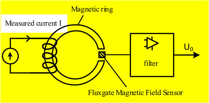
FIGURE 1. Schematic diagram of fluxgate current sensor measurement.
The fluxgate current sensor is mainly composed of a magnetic ring, an energized coil, a fluxgate magnetic field sensor and an amplifying filter circuit. The fluxgate magnetic field sensor can output a voltage signal proportional to the magnetic field, and indirectly measure the magnitude of the current by measuring the magnetic induction intensity generated by the residual current.
The magnitude of the magnetic induction is related to the total current passing through the loop and the magnetic permeability in vacuum. For the residual current, the safe current through the human body is not allowed to exceed 30 mA, and the magnetic permeability of the air is very small, so the magnetic induction intensity generated by the DC residual current in the air is very weak, and it is difficult for the fluxgate sensor to measure the residual current. The value of the current, which requires the sensor to have a high sensitivity (Grim et al., 2020).
It can be seen from the above analysis that adding a magnetic core with higher magnetic permeability can improve the sensitivity of the sensor, or winding more coils on the magnetic ring, so that the weak DC residual current in the ring magnetic circuit can generate a large magnetic induction intensity. The method studied in this paper is to use a magnetic ring with high magnetic permeability to increase the ability of the magnetic focusing ring, which can more easily measure the magnetic field generated by the weak DC residual current. Ampere’s loop theorem in the presence of a magnetic medium:
where
3 Magnetic Ring Design of Open-Loop Fluxgate Current Sensor
Substitute Eq. 2 into Eq. 1 to get:
The above formula is to analyze the current in a wire. If the wire under test is evenly wound on the magnetic ring, then the Ampere loop theorem is also satisfied when there is a magnetic medium (Velasco-Quesada et al., 2016). At this time, the formula can be transformed into:
Where
Among them,
3.1 Selection of Magnetic Ring Materials
It can be seen from the above conclusions that the magnetic ring with low coercivity, high magnetic saturation strength and high magnetic permeability should be selected (Liang et al., 2019). Firstly, the material of the magnetic ring is selected. Common high permeability materials are: iron-based amorphous alloy, silicon steel, ferrite, iron-based nanoalloys etc., The performance indicators are shown in Table 1.
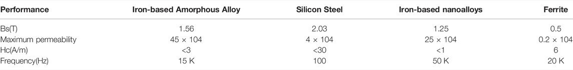
TABLE 1. Performance index of common magnetic materials.
Among the above four materials, ferrite is the most widely used magnetic core material in switching power supplies, but compared with other materials, the magnetic permeability and magnetic saturation induction intensity are the lowest, so it is not selected; although iron-based nanoalloys have high magnetic permeability, they are not suitable for line-segment sensors; silicon steel sheet has high magnetic permeability and magnetic saturation strength, but its resistivity is too small, and the eddy current loss is large at high frequencies, so it is widely used in low frequency occasions (Qi et al., 2019). Therefore, when selecting the magnetic core material, considering the processing difficulty, price, performance, etc., the magnetic material is finally selected as an iron-based amorphous alloy.
3.2 Design of Size Parameters of Magnetic Ring
After the magnetic ring material is determined, the size of the magnetic ring needs to be further determined. The inner diameter of the magnetic ring, the thickness of the magnetic ring, the height of the magnetic ring and the opening size of the magnetic ring will not only affect the size of the induced magnetic field, but also affect the measurement of the leakage current. Therefore, it is necessary to obtain the optimal parameters by controlling the variables.
3.2.1 Magnetic Ring Opening Size Design
The magnetic concentrating ring is open-loop, but magnetic leakage will occur after the open-loop, reducing the magnetic flux detected by the magnetic field sensor, so an appropriate opening size should be designed. The size of the magnetic field sensor is 5 mm*5 mm*1 mm, the opening width of the magnetic ring should be at least 6 mm, the thickness of the magnetic ring should not be less than 5 mm, and the height of the magnetic ring should not be less than 1 mm, so as to ensure that the entire side of the magnetic field sensor is in the magnetic field. The inside of the opening of the ring (Lei, Lei, Zhou).
3.2.2 Simulation of Inner Diameter Change of Magnetic Ring
Wrap two turns of wire around the magnetic ring to increase its sensitivity. It is determined that the inner diameter of the magnetic ring is 16 mm, and the minimum thickness of the magnetic ring is 5 mm, so the minimum outer diameter of the magnetic ring is 26 mm (Macrelli, 2014). As a measuring element, the magnetic field sensor does not contain magnetic permeability components and has little effect on the measured magnetic field, so its relative magnetic permeability is set to 1. The established simulation model is shown in Figure 2.
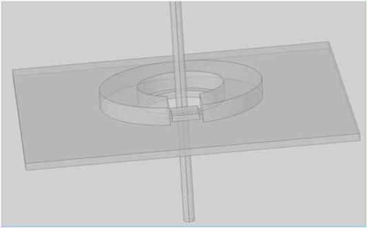
FIGURE 2. Simulation model built.
Set the parameterized scanning range, the scanning range of the limited inner diameter is from 16 to 32mm, that is, the radius is from 8 to 16mm, and the scanning step is 2 mm. According to the theoretical analysis, when the inner diameter of the magnetic core increases, the magnetic path length of the magnetic core will increase, resulting in a decrease in the sensitivity of the sensor. The simulation results of parametric scanning of the inner diameter of the magnetic core are drawn as shown in Figure 3A.
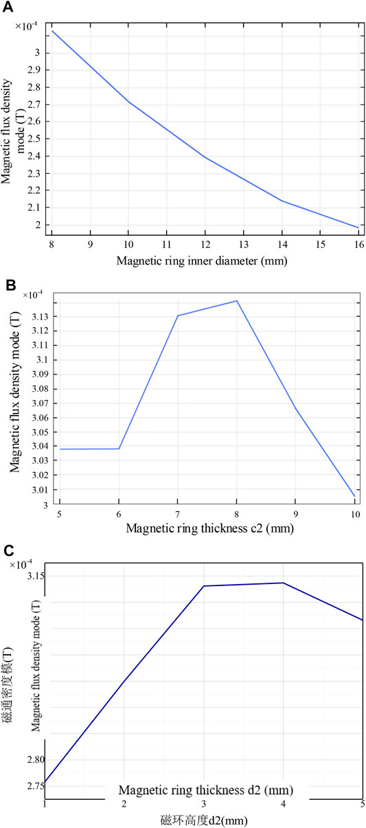
FIGURE 3. Parametric scanning simulation results of the inner diameter of (A) magnetic core, (B) core thickness and (C) magnetic ring height parameterized scanning.
It can be seen from the figure that after the thickness of the magnetic core is fixed, with the increase of the inner diameter of the magnetic core, the average value of the magnetic induction intensity at the cross-section of the magnetic field sensor gradually decreases. Therefore, when the thickness of the magnetic ring is constant, the smaller the inner diameter of the magnetic core, the better the magnetization effect, and the greater the magnetic induction intensity generated at the opening, so the value of the inner diameter should be set to 16 mm.
3.2.3 Simulation of Thickness Change of Magnetic Ring
The difference between the inner and outer diameters of the magnetic ring is the thickness of the magnetic core. Therefore, to determine the outer diameter of the magnetic core, it is necessary to analyze the influence of the thickness of the magnetic core on the magnetic induction intensity at the opening.
According to theoretical analysis, the closer the current position is to the greater the magnetic induction intensity, there is magnetic flux leakage at the edge and less magnetic flux leakage at the center of the magnetic core opening, so the best position for the magnetic field sensor to be placed is in the center of the magnetic core.
Due to the existence of magnetic leakage, the overall magnetic induction intensity at the opening of the magnetic ring is much lower than that inside the magnetic ring, while the magnetic induction intensity inside the opening is stronger than the outside, which is consistent with the previous theoretical analysis. The simulation results of 4 show that the sensor is best placed in the center of the opening of the magnetic core.
The scan range to define the core thickness is 5–10 mm in 1 mm steps. The distribution of the average magnetic induction intensity is analyzed, and the results are shown in Figure 3B. With the increase of the thickness of the magnetic ring, the average magnetic induction intensity of the section first increases slightly, and then begins to gradually decrease. As the thickness of the magnetic ring continues to increase, the size of the opening of the magnetic ring also increases, and the length of the magnetic circuit of the magnetic ring also increases, which will lead to more and more magnetic flux leakage, and the detected magnetic induction intensity will decrease.
The increase of the thickness of the magnetic core will only slightly increase the magnetic induction intensity detected by the magnetic field sensor, which basically reaches the maximum value when the thickness is 8 mm, that is, the outer diameter is 32 mm.
3.2.4 Simulation of the Height Change of the Magnetic Ring
Analyze the effect of the height of the magnetic ring on the magnetic field at the opening of the magnetic ring. According to the previous analysis, the magnetic ring should ensure that the magnetic field sensor is inside its opening, its height is at least 1 mm, and the scanning step length is 1 mm. The change of the average magnetic induction intensity on the cross section of the magnetic field sensor is plotted, and the simulation results are shown in Figure 3C:
In the process of changing the height of the magnetic ring, the value of the average magnetic induction intensity detected by the cross-section first increases slightly, and then begins to gradually decrease. This is because the magnetic field sensor is always located 1 mm away from the bottom of the magnetic core, and the opening edge of the magnetic core will have a certain magnetic flux leakage. As the core height increases, the magnetic field sensor moves away from the open edge of the core, so the average magnetic flux density increases slightly. However, as the height of the magnetic core increases, the opening area and magnetic flux leakage will gradually increase. As can be seen from the figure, when the height of the magnetic core is 3 mm, the average magnetic induction intensity of the cross-section has reached the maximum value, so the height of the magnetic core is set to 3 mm.
Through the above simulation, it can be determined that the parameters of the iron-based amorphous alloy magnetic ring are as follows: the inner diameter is 16 mm, the outer diameter is 32 mm, the thickness is 8 mm, and the height is 3 mm.
4 Experimental Verification
In order to obtain the frequency characteristic and sensitivity of the open-loop fluxgate sensor, the sensor was measured experimentally. The experimental test principle is shown in Figure 4. The output of the arbitrary signal generator is connected to a power amplifier, and the output of the power amplifier is connected to a current-limiting resistor, and a loop is formed through a magnetic ring to simulate the leakage of different waveforms and current values. The first channel of the oscilloscope uses the current clamp meter probe to collect the current waveform in the line, and the second channel collects the output voltage of the sensor.
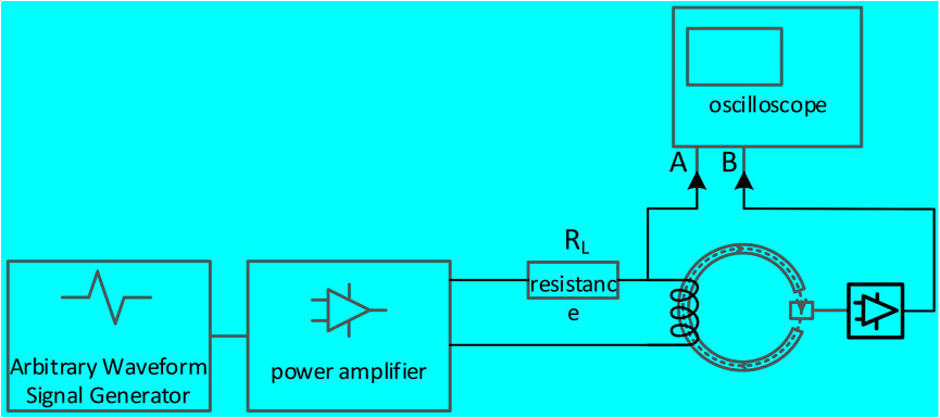
FIGURE 4. Test principal diagram.
In the experiment: adjust the arbitrary signal generator to output 0–10 kHz sine wave sweep frequency, adjust the resistance RL to make the current value in the line 30 mA. By outputting different DC current values, the sensitivity test is carried out on the magnetic field sensor with magnetic focusing ring and the ordinary sensor. The experimental data curve is shown in Figure 5.
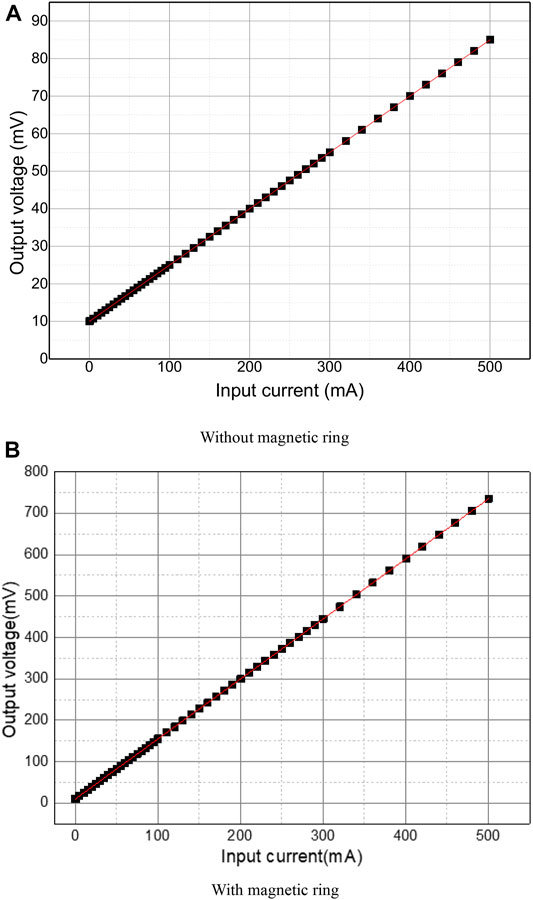
FIGURE 5. Fitting curve results of magnetic field sensor (A) Without magnetic ring, (B) With magnetic ring.
Fitting the data in (Figure 5A), the obtained linear formula is
5 Conclusion
The iron-based amorphous alloy material is selected for the open-loop magnetic focusing ring proposed in this paper, and the inner diameter of the magnetic ring is 16 mm, the outer diameter is 32 mm, the thickness is 8 mm, and the height is 3 mm through simulation. The experimental results show that the fluxgate current sensor with the open-loop magnetic concentrating ring structure can detect the residual current with a bandwidth of 6.7 kHz, a sensitivity of 1.54 mV/mA, and a linearity error of 0.0021%, which can meet the accurate detection of complex residual current waveforms.
Data Availability Statement
The original contributions presented in the study are included in the article/Supplementary Material, further inquiries can be directed to the corresponding author.
Author Contributions
WY: Conceptualization, Writing-Reviewing and Editing; XX: Writing-Original draft preparation, Investigation; QY: Supervision; JH: Visualization and contributed to the discussion of the topic.
Conflict of Interest
Author XX was employed by the company Yunnan Electric Power Technology Co., Ltd. Authors QY, JH, and JW were employed by the company Yunnan Power Grid Co., Ltd.
Publisher’s Note
All claims expressed in this article are solely those of the authors and do not necessarily represent those of their affiliated organizations, or those of the publisher, the editors and the reviewers. Any product that may be evaluated in this article, or claim that may be made by its manufacturer, is not guaranteed or endorsed by the publisher.
Acknowledgments
The authors gratefully acknowledge the support of Research and Application of Key Technologies for Leakage Monitoring, Isolation and Identification of Electricity Violations in Low Voltage Distribution Networks (YNKJXM20191456).
References
Cao, J., Zhao, J., and Cheng, S. (2019). Research on the Simplified Direct-Current Fluxgate Sensor and its Demodulation. Meas. Sci. Technol. 30 (7), 075101. doi:10.1088/1361-6501/ab09bf
Grim, V., Ripka, P., and Bauer, J. (2020). DC Current Sensor Using Switching-Mode Excited Iin-Ssitu Current Transformer. J. Magnetism Magnetic Mater. 500, 166370. doi:10.1016/j.jmmm.2019.166370
Lei, J., Lei, C., and Zhou, Y. (2013). Analysis and Comparison of the Performance of MEMS Fluxgate Sensors with Permalloy Magnetic Cores of Different Structures. Measurement 46, 710–715. doi:10.1016/j.measurement.2012.09.009
Liang, S., Wang, J., Deng, L., Shi, Y., Yin, X., and Shen, Z. J. (2019). An Improved Proportional Base Driver for Minimizing Driver Power Consumption of SiC BJT over Wide Current and Temperature Range. IEEE J. Emerg. Sel. Top. Power Electron. 7 (3), 1727–1735. doi:10.1109/jestpe.2019.2920888
Macrelli, E. (2014). Modeling, Design, and Fabrication of High-Inductance Bond Wire Microtransformers with Toroidal Ferrite Core. IEEE Transactions on Power Electronics (IEEE) 30 (10), 5724–5737. doi:10.1109/TPEL.2014.2370814
Min, Y. Z. (2011). “An AC/DC Sensing Method Based on Adaptive Magnetic Modulation Technology with Double Feedback Properties,” in IEEE International Workshop on Applied Measurements for Power Systems, Aachen, Germany, 28-30 Sept. 2011, 48–52. doi:10.1109/AMPS.2011.6090348
O'Shaughnessy, E., Heeter, J., Shah, C., and Koebrich, S. (2021). Corporate Acceleration of the Renewable Energy Transition and Implications for Electric Grids. Renew. Sustain. Energy Rev. 146, 111160. doi:10.1016/j.rser.2021.111160
Ponjavic, M. M., and Duric, R. M. (2007). Nonlinear Modeling of the Self-Oscillating Fluxgate Current Sensor. IEEE Sensors J. 7 (11), 1546–1553. doi:10.1109/jsen.2007.908234
Qi, J., Yang, X., Li, X., Tian, K., Mao, Z., Yang, S., et al. (2019). Temperature Dependence of Dynamic Performance Characterization of 1.2-kV SiC Power Mosfets Compared with Si IGBTs for Wide Temperature Applications. IEEE Trans. Power Electron. 34 (9), 9105–9117. doi:10.1109/tpel.2018.2884966
Takahiro, K., and Dev, C. (2011). “Wide-range AC/DC Earth Leakage Current Sensor Using Fluxgate with Self-Excitation System,” in IEEE Sensors Conference, Limerick, Ireland, 28-31 Oct. 2011 (IEEE), 512–515. doi:10.1109/ICSENS.2011.6127133
Telukunta, V., Pradhan, J., Pradhan, J., Agrawal, A., Singh, M., and Srivani, S. G. (2017). Protection Challenges under Bulk Penetration of Renewable Energy Resources in Power Systems: A Review:A Review. Csee Jpes 3 (4), 365–379. doi:10.17775/cseejpes.2017.00030
Velasco-Quesada, G. (2010). Design of a Low-Consumption Fluxgate Transducer for High-Current Measurement Applications, IEEE Sensors J. 11, 280–287. doi:10.1109/JSEN.2010.2054831
Velasco-Quesada, G., Roman-Lumbreras, M., Perez-Delgado, R., and Conesa-Roca, A. (2016). Class H Power Amplifier for Power Saving in Fluxgate Current Transducers. IEEE Sensors J. 16 (8), 2322–2330. doi:10.1109/jsen.2016.2516399
Xu, L., Wang, G., Shi, Q. M., Liu, Y., Wu, Y., and Xing, P. X. (2015). A Simplified Modeling of Transient Voltage and Simulation of Direct Drive Permanent Magnet Synchronous Generator. Electr. Mach. Control Appl. 42 (09), 47–51+67. doi:10.1109/PTC.2011.6019425
Xu, Z., and Min, Y. (2009). “Type B RCD with a Simplified Magnetic Modulation Method,” in Proceedings of IEEE 6th International Power Electronic and Motion Control Conference, Wuhan, China, 17-20 May 2009 (IEEE), 769–772. doi:10.1109/IPEMC.2009.5157488
Keywords: fluxgate magnetic field sensor, open loop, magnetic concentrator, magnetic ring, residual current
Citation: Yang W, Xie X, Yang Q and Huang J (2022) Design and Hardware Experiment of Concentrating Magnetic Ring of Current Sensors Used in Open-Loop Fluxgate. Front. Energy Res. 10:926343. doi: 10.3389/fenrg.2022.926343
Received: 22 April 2022; Accepted: 10 May 2022;
Published: 19 July 2022.
Edited by:
Xiaoshun Zhang, Northeastern University, ChinaReviewed by:
Puyu Wang, Nanjing University of Science and Technology, ChinaXueqian Fu, China Agricultural University, China
Copyright © 2022 Yang, Xie, Yang and Huang. This is an open-access article distributed under the terms of the Creative Commons Attribution License (CC BY). The use, distribution or reproduction in other forums is permitted, provided the original author(s) and the copyright owner(s) are credited and that the original publication in this journal is cited, in accordance with accepted academic practice. No use, distribution or reproduction is permitted which does not comply with these terms.
*Correspondence: Xuegang Xie, eHVlZ2FuZ3hpZTIwMjJAMTYzLmNvbQ==