 Qi Yang1
 Xuegang Xie
- 1Lincang Bureau, Yunnan Power Grid Co., Ltd., Lincang, China
- 2Yunnan Electric Power Technology Co., Ltd., Kunming, China
Electrical equipment insulation damage, metal shell conduction on rainy days, and wire short circuits are easy to produce leakage, which form step voltage on the ground and endangers the life and safety of nearby personnel. In addition to the existing leakage protector, a new method is proposed to use leakage energy to obtain energy and early warning. The step voltage generated by the leakage current is collected through the electrode, which is rectified and reduced by the nano power LTC3588, while energy is stored in the supercapacitor for the superheterodyne transmitting module to send the leakage signal to the nearby receiving device. Based on the possibility of the superheterodyne transmitting module sending the leakage signal, it is judged whether leakage occurs here. The experimental results illustrate that when 10 mA leakage occurs in a 220 V wire, the electrode distance is 1.0 m, while the energy extraction device can obtain 360 MW of power for the superheterodyne transmitting module to send the leakage signal.
Introduction
The leakage of electrical equipment generates a step voltage on the ground, which causes an electric shock to the human body (Abigail, 2019; Pompodakis et al., 2021; Aliyari et al., 2022). The existing protection measures are to install leakage protectors. However, due to low sensitivity and easy mis-operation of the leakage protector, it causes frequent tripping and affects the reliability of the power supply (Tong et al., 2013; Ndhlamblenze and Hlalele, 2020; Cai et al., 2021). Electricity leakage often occurs at bus stops and transmission towers with accumulated water, which results in an electric shock from step voltage and touch voltage (Makhchoune et al., 2022). Therefore, it is indispensable to devise an early leakage warning device to ensure the safety of people’s lives. At present, different methods have emerged for the early warning of leakage. Sheng et al. (2014) designed a strategy to obtain the step voltage through a metal rod installed at the bottom of the insulating boot so as to detect the voltage and issue an early warning. The work by Ren et al. (2016) proposed a leakage monitor that is placed on the foot for audible and visual alarm or short circuit protection. In addition, the existing leakage warning devices are all wearable that can only provide protection for the wearer. Thus, it is compulsory to design a general leakage early warning device. The device is installed underground and realizes the self-power supply of the early warning device by collecting leakage energy without installing batteries.
In summary, this study proposes a method of leakage energy extraction and early warning, which uses the leakage current that flows into the Earth to form step voltage power extraction. Through experiments, the influence of the size and laying position of the power extraction electrode on the power extraction is studied. Furthermore, a low-power energy collection circuit is devised to ensure that the system can start normally in the case of leakage, which realizes the rapid early warning of leakage, while experiments verify the feasibility of this method.
Design Principle of Leakage Energy Extraction
The leakage energy and the early warning device collects the step voltage generated by the leakage current to supply power to itself. When the transmission pole tower leaks electricity, the charged body is in direct contact with the ground. Due to the existence of soil resistance, when the leakage current naturally flows from the electrode to the surrounding soil, a pressure drop will be generated in the soil and a certain surface potential distribution will be formed, while the hemispherical area will generate a uniformly distributed voltage drop (Roy and Kundu, 2021), which is depicted in Figure 1A.
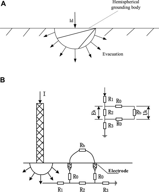
FIGURE 1. Energy dissipation and extraction. (A) Ground current dissipation and (B) schematic diagram of leakage energy extraction.
The leakage energy extraction and early warning device are used as conductors to form a circuit with the Earth. Among them, two electrodes are buried at different potential points while a step potential Ek is formed between the electrodes (Kim et al., 2019; Sunjerga et al., 2019). According to the step voltage principle, current will be generated to supply power for the leakage energy extraction and early warning devices to realize passive self-start. Furthermore, the schematic diagram of leakage energy extraction is shown in Figure 1B. In addition, the contact resistance R0 between the two electrodes and the soil is connected in series with the leakage energy extraction and early warning device Rb. Currently, the actual voltage between the electrodes (i.e., the step voltage Uk) is written as follows:
Design of the Leakage Energy Extraction and Early Warning Device
Overall Structure of the Leakage Energy Extraction and Early Warning Device
The leakage signal obtained from the electrode is an AC signal, while the leakage current is generally less than 50 mA with a small output power. It is inevitable to select the rectifier and DC/DC (direct current-direct current) step-down module with low power consumption to output stable DC. After storage, a stable DC is used for the wireless transmitting module to send a leakage signal, upon which the wireless transmitting module selects the superheterodyne module with extraordinarily low power consumption. In particular, the overall structure of the leakage energy extraction and early warning device is depicted in Figure 2A.
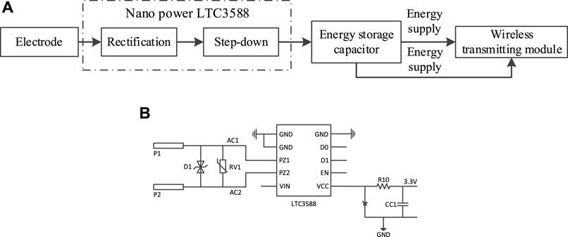
FIGURE 2. Device construction. (A) Overall structure of the self-powered step voltage early warning device and (B) energy collection circuit.
Furthermore, leakage energy extraction and early warning devices are composed of electrodes, nano power LTC3588, an energy storage capacitor, and a superheterodyne transmitting module. The optimized design and laying position of the electrode can maximize the energy of the step voltage. Moreover, a low-loss full bridge rectifier and an efficient step-down converter are integrated with the nanopower LTC3588 chip. In special cases, the full-bridge rectifier converts the AC charge generated by the leakage current into fluctuating DC energy. The step-down converter effectively transfers the internally stored charge to the output (Wang et al., 2015; Zhao and Yang, 2017), while the supercapacitor stores the energy after step-down and voltage stabilization, which drives the superheterodyne transmitter module to send the leakage signal at the same time.
Leakage Energy Circuit Design
The electric leakage energy extraction (Liu et al., 2021) circuit utilizes the step voltage formed by the leakage of the piece of equipment on the ground to obtain energy (Chen et al., 2021). Moreover, the step voltage obtained by the electrode is generally up to 36 V, but the output current is generally tens of milliamps with milliwatt-level output power. There are losses of various factors in the energy collection circuit; a leakage energy collection circuit with low power consumption plays a vital role in design and research. It is worth noting that the voltage obtained by the electrode is AC and unstable, which changes according to the change of external leakage, while the energy required by the superheterodyne emission module is a stable DC voltage (i.e., generally 2–3.6 V). Therefore, in order to enable the superheterodyne transmitter module to obtain energy continuously and stably from the electrodes, a low-power AC/DC conversion circuit needs to be used to convert the alternating current into stable DC. Then, stable DC is stored in the supercapacitor and continuously and stably supplied to the superheterodyne transmitting module.
In this article, a leakage energy extraction circuit based on the nano power LTC3588 energy collection chip is designed, as shown in Figure 2B. The input terminals are PZ1 and PZ2, which are used to connect electrodes P1 and P2. In addition, the output VCC is connected to the supercapacitor CC1 to store charge, upon which the super capacitor is 0.47F and 5.5 V. When current leakage occurs, the electrodes connected at both ends of PZ1 and PZ2 collect the step voltage generated by leakage. After rectification and step-down by the nano power LTC3588 circuit, it outputs a stable DC voltage of 3.3 V, which is stored on the supercapacitor and supplies power to the superheterodyne transmitting module.
AC/DC and Step-Down Modules
The nano power LTC3588 energy collection chip is adopted, which integrates a low-loss full-bridge rectifier and a high-efficiency step-down converter. The nano power LTC3588 will enter the sleep state in the regulation mode. In this state, the input and output quiescent currents are quite small. The step-down converter is turned on and off as required to meet the regulation effect, while the output voltage is set to 3.3 V. Consequently, the nano power LTC3588 converts the AC collected by the electrode into stable DC through a low-loss full bridge rectifier, while the high-efficiency step-down converter reduces DC higher than 3.3 to 3.3 V for subsequent circuits.
In order to prevent the single-phase grounding of the transmission line and the impact of the 220 V on the energy harvesting circuit, there is no doubt that the pressure-sensitive resistor RV1 needs to be placed in front of the nano power LTC3588. When the voltage exceeds the threshold voltage, it will be instantly turned on and will absorb the excess current to protect the subsequent circuit since the design is based on leakage energy extraction and an early warning device that is calculated according to the step voltage of 36 V of a human electric shock. In order to prevent circuit damage caused by the voltage taken by the electrode being greater than 36 V, it is essential to add D1 in front of the rectifier bridge and a 36 V bidirectional TVS. Furthermore, when the voltage is greater than 36 V, it can achieve transient suppression, that is, the high impedance between the two poles becomes low impedance with surge power being absorbed so that the voltage clamp between the two poles is at a predetermined value, which can effectively protect the circuit from surge pulse damage.
Design of the Energy Storage Circuit
The storage unit used in the leakage energy extraction circuit is a supercapacitor, which is generally the Faraday level, with a large capacity and slow self-discharge rate. Furthermore, the self-discharge starts at 5 V while the discharge energy is about 1 V after 10 hours. Moreover, it is relatively simple to use and does not need a special charging and discharging circuit.
Since the output voltage of the nano power LTC3588 energy collection module is set to 3.3 V, a supercapacitor of 0.47 F and 5.5 V is selected. A 5Ω current limiting resistor is connected in series in front of the super capacitor, while a 3.37 V varistor diode is connected in parallel. When the working voltage of the super capacitor is greater than the breakdown voltage of the voltage regulator, the charging current will flow directly from the varistor diode, upon which the voltage of the capacitor will not increase to avoid the overvoltage of the super capacitor. The disadvantage of this method is that the pressure-sensitive diode and current limiting resistor will produce more energy loss, which will result in the heating of the pressure-sensitive diode.
Design of the Early Warning Circuit
In particular, the superheterodyne transmitting module utilizes the output voltage of the leakage energy extraction circuit as the power supply. When the superheterodyne transmitting module transmits the leakage signal to the receiving equipment, it indicates that leakage occurs here. Moreover, when the receiving equipment does not receive the leakage signal, it indicates that the leakage does not occur here so as to realize the early warning function of leakage. Because the energy generated by the leakage is at the milliwatt level, the superheterodyne transmitting module and superheterodyne receiving module are selected.
The superheterodyne transmitting module has a voltage range of 2.0–3.6 V together with a transmitting power of 15 MW, which has a sleep and fast wake-up power supply, zero standby power consumption, and a transmission distance of 15 m. Furthermore, the superheterodyne receiving device can be installed at the site where the transmission tower is 7 m above the ground. In case of electric leakage, the superheterodyne receiving device receives the leakage signal for audible and visual early warning to avoid electric shock to personnel close to the area, which locates the leakage point at the same time.
Experiment and Verification
The physical diagram based on the leakage energy extraction and early warning device is revealed in Figure 3A. The leakage energy extraction and early warning circuit includes a nano power LTC3588 energy collection circuit, supercapacitor, and superheterodyne emission module. The nano power LTC3588 energy collection circuit converts the collected AC voltage into a stable DC voltage, which is stored in the supercapacitor. Then, it supplies power to the superheterodyne transmitting module to continuously transmit the leakage signal and realize leakage early warning.
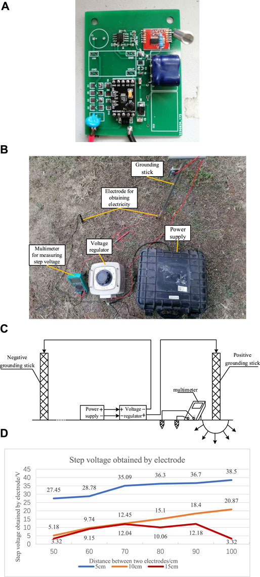
FIGURE 3. Physical and experimental representation. (A) Physical diagram of the leakage energy extraction and early warning device. (B) Electrode laying position experiment. (C) Experimental block diagram of the electrode laying position. (D) Step voltage obtained by the electrode.
Experimental Environment and Results of the Electrode Laying Position
The field simulation experiment is shown in Figure 3B. The 220 V power supply is input to the voltage regulator, which adjusts the voltage to 220 V and inputs it to the grounding stick. Furthermore, the leakage is injected into the ground through the grounding stick to simulate the grounding fault of a 220 V transmission line. The experimental block diagram of the electrode laying position is represented in Figure 3C.
It is worth noting that the buried depth of the electrode is 15 cm, upon which the electrode is laid 5, 10, and 15 cm away from the leakage point. The step voltage observed based on changing the distance between the electrodes is shown in Table 1 and Figure 3D, which can be applied to determine the best laying position of the electrode.
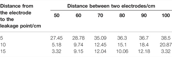
TABLE 1. Step voltage obtained by the electrode.
According to the aforementioned data, when the electrode is inserted into the Earth at a depth of 15 cm, it is 5 cm away from the leakage point together with 100 cm between the two electrodes, upon which the maximum power is obtained.
On-Site Simulation Experiment and Results of the Leakage Energy Acquisition and Early Warning Device
For the purpose of verifying the reliability of the designed leakage energy extraction and early warning circuit, the on-site simulation experiment is illustrated in Figure 4A, while the block diagram of the electricity extraction experiment is depicted in Figure 4B. The 220 V power supply is input to the voltage regulator that adjusts the voltage to 220 V and inputs it to the grounding stick to simulate the ground fault of the 220 V transmission line. The electrodes of the leakage energy extraction and early warning device are buried 5 cm away from the grounding stick, 100 cm apart, and 15 cm deep. The two ends are connected in parallel with a multimeter to measure the step voltage, which is connected in series with a multimeter to measure the leakage. At this time, whether the indicator light of the receiving device is switched on is observed. If it is on, a leakage warning is carried out while the starting time of the superheterodyne transmitting module is measured. The test results are shown in Table 2.
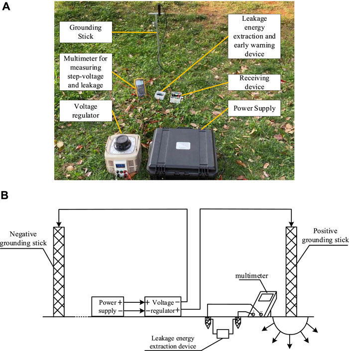
FIGURE 4. On-site simulation experiment. (A) On-site simulation experiment of power supply and (B) block diagram of the electrical experiment.
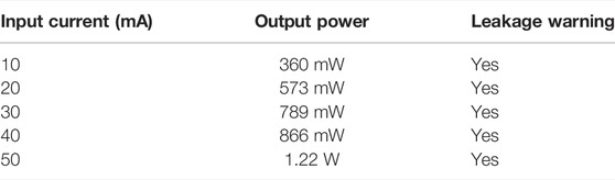
TABLE 2. Experimental results of the energy extraction circuit based on LTC3588.
The experimental results show that when 10 mA leakage occurs in a 220-V wire, the electrode distance is 1.0 m. In particular, the energy extraction device can obtain 360 MW power for the superheterodyne transmitting module to send a leakage signal so as to realize early leakage warning, which further verifies the feasibility of this method.
Conclusion
This article provides a leakage energy extraction and early warning device, while the experimental results indicate that the leakage energy extraction and early warning device can obtain 360 MW power, which proves that the leakage energy extraction and early warning device can take energy from weak leakage and work normally, upon which it meets the rapid response of the early leakage warning device for leakage in the low-power mode so as to verify the feasibility of this method.
Data Availability Statement
The original contributions presented in the study are included in the article/supplementary material; further inquiries can be directed to the corresponding author.
Author Contributions
QY: conceptualization, writing—reviewing and editing; XX: writing—original draft preparation and investigation; JH: visualization and contributed to the discussion of the topic; JW: supervision.
Conflict of Interest
QY, JH, and JW were employed by the company, Yunnan Power Grid Co., Ltd. XX was employed by the company, Yunnan Electric Power Technology Co., Ltd.
Publisher’s Note
All claims expressed in this article are solely those of the authors and do not necessarily represent those of their affiliated organizations, or those of the publisher, the editors, and the reviewers. Any product that may be evaluated in this article, or claim that may be made by its manufacturer, is not guaranteed or endorsed by the publisher.
Acknowledgments
The authors gratefully acknowledge the support of Research and Application of Key Technologies for Leakage Monitoring, Isolation, and Identification of Electricity Violations in Low-Voltage Distribution Networks (YNKJXM20191456).
References
Abigail, G. B. (2019). Controlling Leakage Through Installed Geomembranes Using Electrical Leak Location. Geotext. Geomembranes 47 (5), 697–710. doi:10.1016/j.geotexmem.2019.103501
Aliyari, M., Jannati, M., Dolatshahi, M., and Rezaei, M. M. (2022). A Four-Step Protection Strategy to Improve Stability of High Voltage Transmission Lines. Electr. Power Syst. Res. 208, 107922. doi:10.1016/j.epsr.2022.107922
Cai, Y., Ji, H., Wang, D., Lei, X., Sun, Y., and Yuan, S. (2021). Optimal Construction Method and Demonstration Application of Multi-In-One Station Grounding System. Glob. Energy Interconnect. 4 (5), 520–530. doi:10.1016/j.gloei.2021.11.005
Chen, Z., Shi, J., Li, Y., Ma, B., Yan, X., Liu, M., et al. (2021). Recent Progress of Energy Harvesting and Conversion Coupled with Atmospheric Water Gathering. Energy Convers. Manag. 246, 114668. doi:10.1016/j.enconman.2021.114668
Kim, B., Ryu, K.-S., Kim, D.-J., Nam, Y.-H., Ko, H., and Kim, H.-C. (2019). A Study on the Voltage Control Method of Primary Feeder by the Energy Storage System and Step Voltage Regulator. IFAC-PapersOnLine 52 (4), 431–436. doi:10.1016/j.ifacol.2019.08.248
Liu, C., Zhao, R., Yu, K., Lee, H. P., and Liao, B. (2021). Simultaneous Energy Harvesting and Vibration Isolation via Quasi-Zero-Stiffness Support and Radially Distributed Piezoelectric Cantilever Beams. Appl. Math. Model. 100, 152–169. doi:10.1016/j.apm.2021.08.002
Makhchoune, M., Benhayoun, O., Laaidi, A., Haouas, M. Y., Naja, A., and Lakhdar, A. (2022). Extra Dural Hematoma Following a High Voltage Electrocution Accident: A Case Report. Ann. Med. Surg. 73, 103157. doi:10.1016/j.amsu.2021.103157
Ndhlamblenze, S., and Hlalele, T. S. (2020). Earth Grid Design for 400KV Neiuwehoop Substation Using CDEGS Platform. 2020 IEEE PES/IAS PowerAfrica, 1–5.
Pompodakis, E. E., Kryonidis, G. C., and Alexiadis, M. C. (2021). A Comprehensive Three-Phase Step Voltage Regulator Model with Efficient Implementation in the Z-Bus Power Flow. Electr. Power Syst. Res. 199, 107443. doi:10.1016/j.epsr.2021.107443
Ren, J., Wang, L., Hao, J. H., and Hu, X. P. (2016). Preliminary Design of a New Type of Step Voltage Monitor. J. Shandong Industrial Technol. 2, 201. doi:10.16640/j.cnki.37-1222/t.2016.02.178
Roy, S., and Kundu, C. K. (2021). State of the Art Review of Wind Induced Vibration and its Control on Transmission Towers. Structures 29, 254–264. doi:10.1016/j.istruc.2020.11.015
Sheng, H. S., Lu, Q., and Yan, J. R. (2014). Development of Step Voltage Detection and Alarm Device Based on ARDUINO. Sci. Technol. Inf. 12 (30), 104–105. doi:10.16661/j.cnki.1672-3791.2014.30.082
Sunjerga, A., Li, Q., Poljak, D., Rubinstein, M., and Rachidi, F. (2019). Isolated vs. Interconnected Wind Turbine Grounding Systems: Effect on the Harmonic Grounding Impedance, Ground Potential Rise and Step Voltage. Electr. Power Syst. Res. 173, 230–239. doi:10.1016/j.epsr.2019.04.010
Tong, R.-t., Guo, L.-z., and Cao, Z. (2013). The Analysis in Several Application Issues for Leakage Current Electrical Fire Monitoring System. Procedia Eng. 52, 342–348. doi:10.1016/j.proeng.2013.02.151
Wang, X., John, S., Watkins, S., Yu, X., Xiao, H., Liang, X., et al. (2015). Similarity and Duality of Electromagnetic and Piezoelectric Vibration Energy Harvesters. Mech. Syst. Signal Process. 52-53, 672–684. doi:10.1016/j.ymssp.2014.07.007
Keywords: leakage energy, leakage warning, electrode, nano power LTC3588, step voltage
Citation: Yang Q, Xie X, Huang J and Wu J (2022) Power Leakage Monitoring and Warning Device for Power Grid Fault Diagnosis: Design and Field Test. Front. Energy Res. 10:926357. doi: 10.3389/fenrg.2022.926357
Received: 22 April 2022; Accepted: 13 May 2022;
Published: 29 June 2022.
Edited by:
Xiaoshun Zhang, Northeastern University, ChinaReviewed by:
Xueqian Fu, China Agricultural University, ChinaJiawen Li, South China University of Technology, China
Copyright © 2022 Yang, Xie, Huang and Wu. This is an open-access article distributed under the terms of the Creative Commons Attribution License (CC BY). The use, distribution or reproduction in other forums is permitted, provided the original author(s) and the copyright owner(s) are credited and that the original publication in this journal is cited, in accordance with accepted academic practice. No use, distribution or reproduction is permitted which does not comply with these terms.
*Correspondence: Xuegang Xie, eHVlZ2FuZ3hpZTIwMjJAMTYzLmNvbQ==