 Yuan Tang
 Conghuan Yang
 Zuanhong Yan
 Ying Xue
 Yi He
Yi He- 1School of Electric Power Engineering, South China University of Technology, Guangzhou, China
- 2Department of Electronic, Electrical and System Engineering, University of Birmingham, Birmingham, United Kingdom
- 3Quant-Cloud Energy Co, Ltd., Shenzhen, China
- 4Department of Electrical Engineering, The Hong Kong Polytechnic University, Kowloon, China
Fast-frequency regulation (FFR) is becoming a key measure to enhance the frequency stability of power systems as the penetration of renewables and power electronics continues to grow and the system inertia declines. Although different control methods have been proposed to provide a wind turbine generator (WTG) with a limited capability of virtual inertia and frequency support, the coordination between the WTG and a battery energy storage system (BESS), as well as the potential optimization benefits, have not been fully studied. This study proposes a coordinated control of WTG and BESS that provides FFR to the AC system and at the same time extends the cycle life of the battery. First, a cost effective and SOC-based FFR strategy of BESS alone was proposed. Then, a coordinated FFR method for the WTG–BESS hybrid system under all wind speeds was proposed by analyzing the operational characteristics of WTG. The proposed coordinated strategy improves the FFR performance with a longer cycle life and lower cost of battery under different operating conditions. Simulation results based on varying wind speeds indicate that the proposed FFR strategy raises the frequency nadir and avoids the frequency secondary dip.
1 Introduction
A rapid development of renewable energy is becoming a global consensus. Over 10 countries have set targets to increase the installed capacity of renewable energy to meet 50% of total energy demands (Kurbatova and Perederii, 2020). At the same time, the increasing penetration of converter-interfaced renewable power causes issues regarding frequency stability. Variable-speed wind turbine generators (WTGs) normally operate under the maximum power point tracking (MPPT) mode to obtain the maximum output at a certain wind speed; thus, their power output is decoupled from the system frequency. As the WTGs gradually replace the conventional synchronous generators (SG), the inertia reserve of the power system is further reduced, and the frequency-regulation capability is thus weakened (Lin and Wu, 2020).
Nowadays, many countries have regulations in place for grid-connected WTG to provide frequency regulation to the system. For instance, the United Kingdom National Grid requires onshore wind farms to provide short-term frequency support and automatic generation control ability (Dallmer-Zerbe et al., 2017). Hence, the methods of frequency support have been proposed and can be divided into two categories: power reserve control and kinetic energy control (Attya and Dominguez-García, 2018). For kinetic energy control, WTGs release the kinetic energy of the rotor to provide frequency support. However, this method works only a very short period of time (<5 s) and suffers the drawback of frequency secondary dip (FSD) when the rotor speed recovers, especially under low-speed conditions (Jin et al., 2018). For power reserve control, overspeeding and pitch deloading methods allow WTGs to leave a margin of active power to meet the frequency support requirements (Li et al., 2016; Wang et al., 2018; Datta et al., 2020). However, the significant cost of wind power curtailment reduces the financial benefits and usually makes this method infeasible (Motamed et al., 2013).
In the past few years, the development of battery energy storage systems (BESSs) has also driven research on frequency support (Zhang et al., 2014). The fast response and precise power-tracking characteristics of BESSs make them attractive solutions considering the technical difficulties encountered by the frequency support using WTG, as discussed above (Sun et al., 2020). Studies have discussed the inertia control and frequency regulation based on WTG and BESS together (Xu et al., 2013; Gao, 2014; Wu et al., 2015; Sato et al., 2020). However, none of them considered potential benefits of coordinated operations. The high cost of BESS investment remains an obstacle to large-scale application. Considering the economic feasibility of wind-storage hybrid systems, studies by Dang et al. (2012) and Miao et al. (2015) proposed coordinated frequency-regulation strategies based on the state of charge (SOC) feedback to improve the battery efficiency and smooth the frequency variations. However, simply setting the upper and lower SOC limits cannot achieve desired performances under changing network and wind conditions. Hao et al. (2015) discussed a hybrid frequency-regulation strategy using adaptive fuzzy control, which improves the frequency regulation accuracy of wind farm and supercapacitor, while optimizing the capacity of supercapacitor to reduce the investment cost. Zhang et al. (2018) optimized the battery capacity based on the frequency droop control with a fixed droop coefficient to maintain a constant BESS power output. A coordinated virtual synchronous generator control of photovoltaic and battery systems for grid support was also studied by Liu et al. (2022). Xiong et al. (2021) discussed a frequency response strategy based on fast power compensation in low-inertia power systems.
In this study, the coordination and optimal operation of a hybrid system of WTG and BESS were examined to 1) provide high-performance fast-frequency regulation (FFR) at all wind speeds, and 2) optimize the SOC management to extend the cycle life of battery, thus further decreasing the lifecycle investment cost. The main contributions of this study are as follows
1) Compared to the conventional method, the frequency nadir is further raised under the proposed coordinated control of the WTG–BESS hybrid system.
2) Compared to controlling the BESS alone, the proposed SOC-based control optimizes the SOC management and extends the cycle life of battery.
3) The technoeconomic feasibility of using BESS to support the system frequency was analyzed and improved, with either better performance of frequency regulation or lower cost of BESS.
4) The proposed SOC-feedback droop control integrates real-time battery SOC and conventional droop control to maintain SOC, reducing the additional penalty costs and eliminating the FSD.
The rest of this study is organized as follows. Section 2 discusses the selection of battery, BESS capacity dimensioning, and the impacts of battery SOC on its cycle life. Section 3 proposes the SOC-based droop control of BESS and the coordinated FFR method of the WTG–BESS hybrid system. Section 4 presents case studies based on time domain simulations to demonstrate the proposed method. At last, Section 5 cconcludes the study.
2 Technoeconomic Feasibility Study of Battery Energy Storage System
In order to clarify the technical and economic benefits of the proposed coordinated control method, it is necessary to analyze the economic feasibility of using BESS to provide FFR under certain technical conditions. Three aspects were discussed:
1) Technical characteristics of different types of battery
2) Dimensioning of the BESS capacity
3) Impacts of SOC on the cycle life of battery
Different Types of Battery
As for different types of battery, key factors of considerations were investment cost, energy density, response time, cycle life, efficiency, and safety. So far, the applications of battery storage have been dominated by lithium-ion batteries. Table 1 shows the dominant types of battery and their technical characteristics (Wang and Liu, 2017; Zhao et al., 2019).
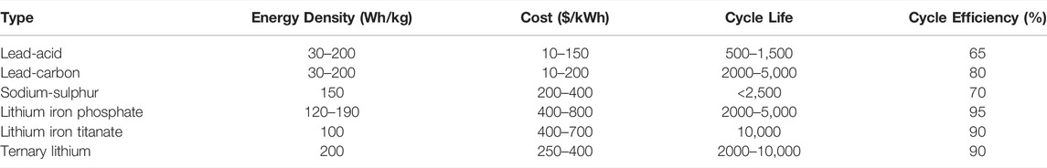
TABLE 1. Technical characteristics of different types of battery.
The investment costs of lead–acid and lead–carbon batteries are low, but these batteries are being phased out due to low energy density and pollution. Lithium-ion batteries dominate all performance indicators, including high-energy density and long cycle life. In particular, lithium–iron–phosphate has a cycle efficiency of about 95%. Therefore, the rest of analysis in this study is based on the lithium–iron–phosphate battery, for its good balance between technical features, cost, and safety. With the latest technical and craftsmanship progresses of the lithium–iron–phosphate battery, it is believed that it makes a better option than ternary lithium for grid-connected applications owing to upgraded energy density and superior safety.
Dimensioning of the Battery Energy Storage System Capacity
Overdimensioned capacity of BESS leads to a higher investment cost, while underdimensioned capacity leads to worse frequency-regulation performance and FSD due to frequency support interruptions. It is important to precisely design the BESS capacity and make the best use of it.
So far, there is no consensus on how to dimension the capacity for the purpose of FFR. One idea is to view the role played by FFR as that similar to the inertia response of conventional SG. Both share the same purpose to prevent the frequency nadir from being too low before the primary frequency regulation kicks in. On this basis, the principle of BESS dimensioning is to assume that it releases the same energy as that released by an SG from a rated grid frequency to the lower limit in a certain period of time.
As an example, in a severe underfrequency event, the system frequency could drop from 50 to 48 Hz, and the corresponding SG rotor speed ranges from 1.0 p. u. to 0.96 p. u. The maximum kinetic energy released by the SG can be calculated as
where
where
The left side is EBESS = PBESSt1. As to the right side, from (1) and (2), △Ek = 0.0784·(1/2)Jωn2 = 0.0784PnH. Therefore, we have
It is reasonable to assume
The above calculation shows the dimensioning of BESS for the requirements of FFR and its relationship with the lower limit of the system frequency. Note that the calculated result of 8% Pn is for a rather severe underfrequency situation. In practice, the dimensioning of the BESS capacity would depend on the network requirement. In reality, the system frequency can hardly drop <49.5 Hz; therefore, the required battery capacity could be even smaller.
Impacts of State of Charge to the Cycle Life of Battery
SOC is the ratio of the real-time charge and the total charge in a fully charged state. When participating in the frequency regulation, BESS needs to consider not only the target power demand, but also the frequency-regulation capacity that its own SOC can provide. In addition, the penalty cost of SOC to be beyond its upper and lower limits is also considered in the economic impact of SOC on the battery life.
In practical applications, the more energy a battery exchanges with the network before reaching the cycle life, the higher efficiency is achieved and the more financial benefits it brings. However, the rate of battery aging is closely related to the operating conditions. One key factor is the depth of discharge (DOD). The DOD of a complete discharge is 100%. Figure 1 shows the attenuation relationship between the DOD of a lithium–iron–phosphate battery and its cycle life (Li et al., 2019).
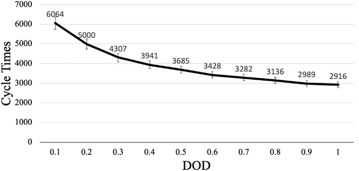
FIGURE 1. Relationship between the battery depth of discharge and its cycle life.
As shown in Figure 1, the increasing DOD accelerates the rate of battery aging, reaching a minimum cycle life at a DOD of 1.0. The reduced cycle life of the battery increases its economic investment. Therefore, discharging the battery at its maximum DOD depth in every cycle is undesirable. From the above analysis, the energy management of BESS first requires an analysis of the SOC interval model.
As an electrochemical energy storage, the structure of the lithium-ion battery shows that overcharging or discharging would reduce the available capacity and shorten the cycle life (Yan et al., 2020). More serious problems could happen when the battery releases too much energy for frequency regulation and the SOC drops to a very low level close to zero. Therefore, the BESS needs to regulate the charge and discharge power based on real-time SOC feedback. A reasonable upper and lower SOC limit for the operation of BESS hence becomes significant in ensuring satisfactory BESS participation in the frequency regulation. The established SOC interval model is presented in Figure 2.
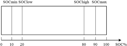
FIGURE 2. State of charge (SOC) interval model.
SOC is divided into four intervals by four thresholds: overdischarge threshold
1) When
2) When
3) When
4) When
The above four intervals will be used for the proposed control of BESS, allowing batteries to adjust their output power according to SOC in a timely manner, which helps to extend the cycle life of battery.
3 State of Charge–Based Droop Control and Coordinated Fast-Frequency Regulation Method
State of Charge–Based Droop Control for Battery Energy Storage System
Based on the conventional frequency droop control and the technical–economic feasibility analysis of BESS in Section 2, Figure 3 shows the proposed SOC-based droop control. The control scheme consists of two modules: the p–f frequency droop and SOC–p constraint.

FIGURE 3. SOC-based frequency droop control for battery energy storage system (BESS).
The conventional p–f droop control does not consider battery SOC, and it has a fixed droop coefficient. When BESS is charged and discharged to SOC limit, it shortens the BESS lifecycle and brings FSD, hence increasing economic costs.
To avoid BESS being charged and discharged to the SOC limit, the BESS SOC has been proposed as an input variable to constrain the power reference
Hence, it has
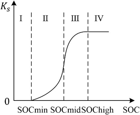
FIGURE 4. Schematic for constraint.
In Figure 4, the x- and y-axis are the BESS SOC and
1) Zone I (0–10%):
When
2) Zone II (10–50%):
In Zone II,
3) Zone III (50–80%):
In Zone III,
4) Zone IV (80–100%)
In Zone IV,
Equations 6 and 7 jointly were designed based on the following principles: 1) Ks = 1 under SOC_max; 2) Ks = 0 under SOC_min; 3) Ks(SOC) should be a continuous function; and 4) Ks should be larger than a linear selection in Zone III when SOC is relatively high to effectively provide FFR, while being smaller than a linear selection in Zone II when SOC is relatively low to protect the battery. Equations 6 and 7 were designed so that it meets these four principles. Other higher-level function designs are possible as long as these principles are met, yet the functions of Ks presented as above are straightforward in math given the same principles. In Equations 6 and 7, the coefficient 10 is simply an integer large enough to make Ks− > 0 when SOC = SOC_min and Ks− > 1 when SOC = SOC_high, while simultaneously not too large to avoid making Ks(SOC) close to a step function. In a power system, the frequency is not regulated only by one device, but a great number of different devices together, and each has a different real-time SOC. The power deficit from devices with low SOC would be compensated by other devices with high SOC.
Coordinated Fast-Frequency Regulation Method of the Hybrid System
The WTG has different levels of kinetic energy reserves that can be provided at varying wind speeds. Therefore, the WTG–BESS hybrid system needs to be coordinated to provide frequency regulation under the following three wind speed conditions.
Low wind speed (6–9 m/s): The WTG operates in the MPPT mode in this wind speed range with insufficient kinetic energy reserves. When a WTG releases its kinetic energy causing a fall of its rotor speed to be below the lower speed limit (0.8 p. u.), the FSD will happen when restoring the rotor speed. To eliminate FSD, BESS will participate in frequency regulation when the wind speed is low.
Medium wind speed (9–12 m/s): The WTG has sufficient kinetic energy to support the system frequency. Under this condition, the WTG and the BESS provide FFR jointly.
High wind speed (above 12 m/s): The WTG maintains its maximum power output at rated values at high wind speeds by regulating the pitch angle. If the WTG provides extra power to regulate the system frequency drop, its power output will exceed the rated value. Therefore, at high wind speeds, only BESS participates in frequency regulation.
The above coordinated FFR method is summarized in Table 2. The FFR control of the turbine alone is the classical proportional and differential frequency-feedback control, as shown in Figure 5, which is not repeated in this study.
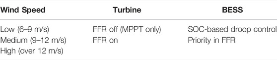
TABLE 2. Coordinated frequency support strategy.
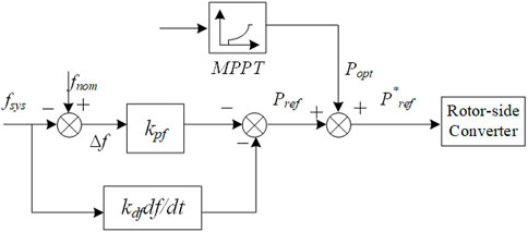
FIGURE 5. Virtual inertia control scheme for doubly-fed induction generator–based wind turbines.
4 Case Studies
To verify the effectiveness of the proposed method, a WTG–BESS hybrid system was modeled in MATLAB/Simulink. The single-line diagram of the system is presented in Figure 6.
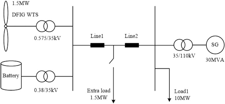
FIGURE 6. Single-line diagram of the wind turbine generator–BESS hybrid system.
The WTG is based on a turbine model with a rated power of 1.5 MW. It is connected to a 40-km 35–kV transmission line parallel with a 12.5 kWh BESS. The SG is 30 MW. The load 1 in the system is a constant power load with a rated power of 10 MW. The rated system frequency is 50 Hz. Appendix Table A1 shows the parameters of the overall system. Appendix Tables A2 and A3 show the parameters of the WTG (doubly-fed induction generator [DFIG] in this case) and the transmission line, respectively.
For the case studies, a step load change of 1.5 MW was considered. Given the proposed method in this study, we are particularly interested in how it works under different wind speeds and SOC levels. In Cases 1–3, three different wind speeds of 7, 11, and 13 m/s are simulated to verify and compare the control performance of the coordinated FFR method under low, medium, and high wind speed conditions. The initial battery SOC is set as 85%. Case 4 is simulated under different levels of battery SOC to verify the impacts.
Case 1: Low Wind Speed
The wind speed is set to 7 m/s, and an extra load of 1.5 MW is added at 20 s. When the frequency drops, only BESS provides frequency regulation. Figure 7 presents the simulation results.
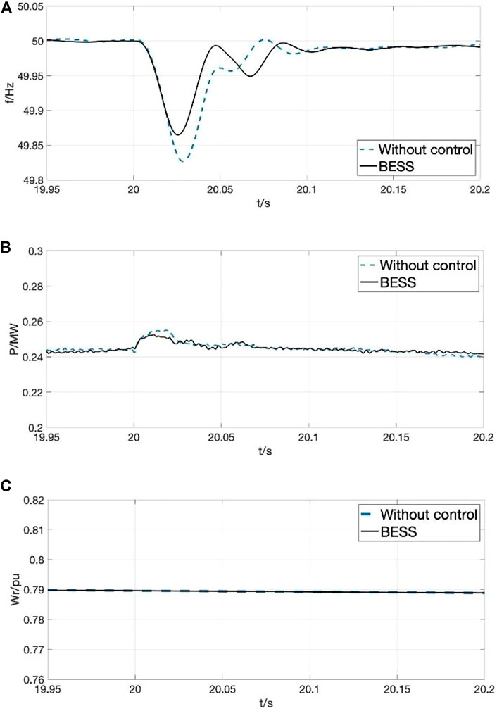
FIGURE 7. Results for case 1. (A) system frequency. (B) turbine output power. (C) rotor speed of turbine.
Figure 7A shows that the frequency nadir is raised from 49.83 to 49.86 Hz with FFR provided by BESS. In the low wind speed condition, the turbine does not participate in the frequency regulation, and it follows the MPPT control only. Figure 7D shows that the BESS releases energy to support frequency with a response time of <20 ms. Figure 7C shows the rotor speed of the WTG is 0.79 p. u. below the lower limit of 0.8 p. u. It validates the necessity and feasibility of the coordinated strategy of only allowing BESS to provide frequency support at low wind speeds.
In conclusion, BESS provides the full FFR in this case and has shown good frequency control performances. The dimensioned capacity BESS does not lead to excessive investment costs or the penalty cost of inadequate frequency support. A reasonable distribution of output power between the BESS and WTG reduces wind energy losses and ensures the economic feasibility of the hybrid system.
Case 2: Medium Wind Speed
In this case, the wind speed is set to 11 m/s, and the extra load of 1.5 MW is added at the 20 s. The simulation results are shown in Figure 8.
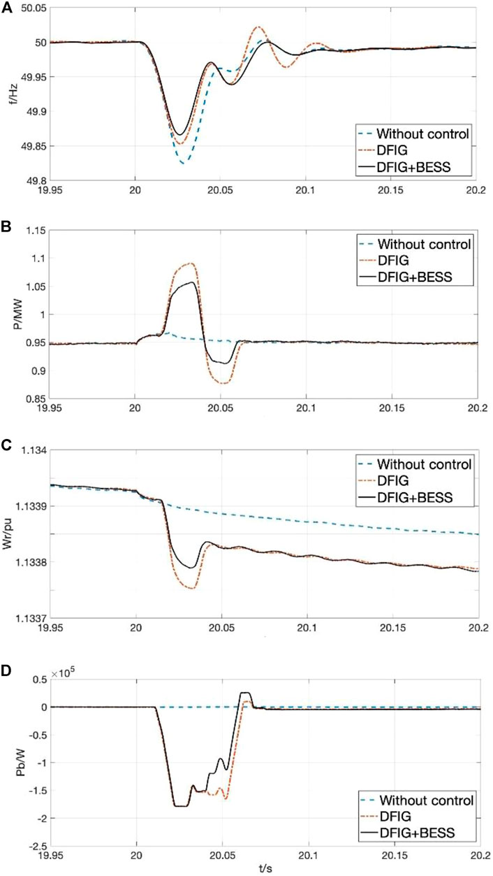
FIGURE 8. Results for case 2. (A) system frequency. (B) turbine output power. (C) rotor speed. (D) output power of the BESS.
Figure 8A shows the frequency-regulation performance using the proposed method under medium wind speed. The highest frequency nadir is 49.87 Hz, which is 0.05 Hz higher than 49.82 Hz in the without control mode. In the DFIG mode, when only the DFIG-based WTG provides frequency support via virtual inertia control, the nadir is raised by 0.3 Hz compared to that without control. Furthermore, the system frequency suffers less oscillation and reaches the steady state faster due to the additional frequency support from BESS. Figure 8B shows the output power of the turbine under different controls. It increases to regulate the frequency and decreases to recover the rotating speed of turbine afterwards. The output power of DFIG decreases from 1.09 MW when it supports frequency alone to 1.056 MW when BESS further assists the frequency support. Figure 8C shows the rotor-speed variations. The rotor speed drops during the underfrequency event, releasing power to provide frequency support. The rotor-speed variation under the DFIG + BESS mode is smaller than that under the DFIG mode.
In conclusion, the coordinated control provides frequency support improved performances. On the one hand, the hybrid system shares the output energy of the BESS, while making reasonable use of the kinetic energy to provide frequency support. For a set DOD of 0.9, the aging rate of BESS is slowed down, which reduces the operation and maintenance costs of BESS.
Case 3: High Wind Speed
The wind speed is set to 13 m/s and other conditions remain the same as in case 2. Figure 9 shows the simulation results for different control modes.
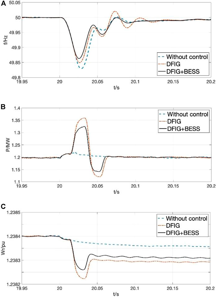
FIGURE 9. Results for case 3. (A) system frequency. (B) turbine power output. (C) rotor speed.
Figure 9A shows the raised frequency nadir to a maximum of 49.87 Hz under the proposed FFR method. As shown in Figures 9B and 9C, the rotor speed decreases, releasing kinetic energy to provide frequency support to the system. Therefore, the output power is raised accordingly. However, compared to case 2, the difference shown in Figure 9B is that the DFIG is capable of increasing its output power by 0.16 MW, which is 0.02 MW greater than that at a medium wind speed in Figure 8B. The rotor can store more kinetic energy at higher wind speeds, allowing for better frequency-regulation performance.
Case 4: Impacts of State of Charge
In this case, the proposed coordinated control is demonstrated with different levels of the SOC of battery to verify the proposed SOC–p constraint.
As shown in Figures 10A and 10B, the BESS reaches a maximum active output of 0.18 MW at 85% SOC, and the frequency nadir is also the highest. When the SOC drops to 40%, the constraint coefficient Ks in the SOC–p module constrains the power output of the BESS to 0.15 MW, and when the SOC reaches the lower limit of 10%, the BESS enters the charging state and thus it does not participate in frequency support. Although the frequency-regulation performance weakens as the BESS output decreases, slowing of the SOC decline can further extend the battery life. For operators of the hybrid system, a prolonged period of BESS output power at maximum DOD raises the investment cost of battery. In summary, the simulation results show that the proposed SOC–p module can effectively limit the fall of SOC to prevent FSD in the system. In addition, the hybrid system can achieve more financial benefits using this method, balancing the safety of the frequency-regulation service with its economic viability.
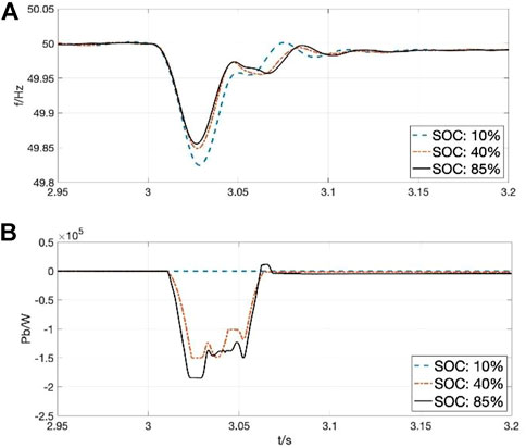
FIGURE 10. Results for case 4. (A) system frequency. (B) output power of the BESS.
However, it is important to point out that batteries will inevitably age over time. When faced with the same frequency-regulation requirement, especially at low wind speeds where the BESS is operating alone, the total number of hours during which BESS provides frequency support is decreased by the reduction in available capacity. In addition, the weakening of the available power output due to battery aging can have a significant impact on control performance, which can threaten the grid safety and stability. Therefore, regular maintenance and replacement of the battery units is a necessity with BESS. A mix of energy storage devices can also be applied to further reduce the rate of battery aging, for example, by using supercapacitors to compensate for the frequency support of the batteries at low SOC.
5 Conclusions
This study proposed a SOC-based droop control of BESS and a coordinated FFR method of the WTG–BESS hybrid system. The proposed control strategy can provide FFR to the power system with satisfactory performances.
As to FFR by BESS, the battery type and capacity dimensioning are determined based on the technical and economic analysis of BESS, and a SOC-based droop control is proposed based on the SOC interval model. By constraining the BESS output and maintaining the SOC, the frequency-regulation performance is guaranteed with limited capacity while extending the battery life.
As for the coordinated FFR control of the WTG–BESS hybrid system, the method allocates the output power between the turbine and BESS at different wind speeds. Furthermore, it brings additional frequency support from utilizing the kinetic energy of DFIG.
The proposed control methods were demonstrated using MATLAB/Simulink simulations under different wind speeds and SOC conditions. Our results demonstrate the following advantages:
1) The highest frequency nadir compared to no control, BESS alone, and WTG alone conditions
2) Applicable to all wind speeds
3) Extending the cycle life of battery through SOC management and improving the economic feasibility of the proposed method
Data Availability Statement
The raw data supporting the conclusions of this article will be made available by the authors, without undue reservation.
Author Contributions
Conceptualization and formal analysis, YT; investigation, ZY; resources and supervision, YX; validation and writing—original draft preparation, CY; writing—review and editing, YH. All authors have read and agreed to the published version of the manuscript.
Funding
This work is funded by China Postdoctoral Science Foundation 2020M682704.
Conflict of Interest
Author ZY was employed by Quant-Cloud Energy Co, Ltd.
The remaining authors declare that the research was conducted in the absence of any commercial or financial relationships that could be construed as a potential conflict of interest.
Publisher’s Note
All claims expressed in this article are solely those of the authors and do not necessarily represent those of their affiliated organizations, or those of the publisher, the editors, and the reviewers. Any product that may be evaluated in this article, or claim that may be made by its manufacturer, is not guaranteed or endorsed by the publisher.
APPENDIX
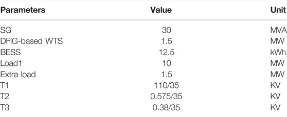
TABLE A1. Parameters of the overall hybrid system.
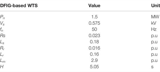
TABLE A2. Parameters of the doubly-fed induction generator–based wind turbines.

TABLE A3. Parameters of the transmission line.
References
Attya, A. B. T., and Dominguez-García, J. L. (2018). Insights on the Provision of Frequency Support by Wind Power and the Impact on Energy Systems. IEEE Trans. Sustain. Energy 9 (2), 719–728. doi:10.1109/tste.2017.2759503
Dallmer-Zerbe, K., Spahic, E., Kuhn, G., Morgenstern, R., and Beck, G. (2017). “Fast Frequency Response in UK Grid — Challenges and Solution,” in 13th IET International Conference on AC and DC Power Transmission (ACDC 2017) (Manchester, UK: IEEE), 1–6.
Dang, J., Seuss, J., Suneja, L., and Harley, R. G. (2012). “SOC Feedback Control for Wind and ESS Hybrid Power System Frequency Regulation,” in 2012 IEEE Power Electronics and Machines in Wind Applications (Denver, CO, USA: IEEE), 1–7. doi:10.1109/pemwa.2012.6316384
Datta, U., Shi, J., Kalam, A., and Li, J. (2020). “DFIG Pitch Angle Control with PID-type Fuzzy Logic Controller in a Microgrid,” in 2020 15th IEEE Conference on Industrial Electronics and Applications (ICIEA) (Kristiansand, Norway: IEEE), 258–263. doi:10.1109/iciea48937.2020.9248090
Gao, C. (2014). “An Wind Turbines and Energy Storage Joint Tuning Scheme Applying to High Wind Power Penetration Power Grid,” in 2014 International Conference on Power System Technology (Chengdu, China: IEEE), 3046–3051. doi:10.1109/powercon.2014.6993550
Hao, X., Zhou, T., Wang, J., and Yang, X. (2015). “A Hybrid Adaptive Fuzzy Control Strategy for DFIG-Based Wind Turbines with Super-capacitor Energy Storage to Realize Short-Term Grid Frequency Support,” in 2015 IEEE Energy Conversion Congress and Exposition (ECCE) (Montreal, QC, Canada: IEEE), 1914–1918. doi:10.1109/ecce.2015.7309930
Jin, X., Xie, Z., Zhang, X., Niu, L., and Gao, X. (2018). “A Control Strategy for DFIG-Based Wind Turbines Based on the Fulfilment of Virtual Inertia,” in 2018 IEEE International Power Electronics and Application Conference and Exposition (PEAC) (Shenzhen, China: IEEE), 1–5. doi:10.1109/peac.2018.8590613
Kurbatova, T., and Perederii, T. (2020). “Global Trends in Renewable Energy Development,” in 2020 IEEE KhPI Week on Advanced Technology (KhPIWeek) (Kharkiv, Ukraine: IEEE), 260–263. doi:10.1109/khpiweek51551.2020.9250098
Li, B., Mo, X., and Chen, B. (2019). Direct Control Strategy of Real-Time Tracking Power Generation Plan for Wind Power and Battery Energy Storage Combined System. IEEE Access 7, 147169–147178. doi:10.1109/access.2019.2946453
Li, P., Hu, W., Hu, R., and Chen, Z. (2016). “The Integrated Control Strategy for Primary Frequency Control of DFIGs Based on Virtual Inertia and Pitch Control,” in 2016 IEEE Innovative Smart Grid Technologies - Asia (ISGT-Asia) (Melbourne, VIC, Australia: IEEE), 430–435. doi:10.1109/isgt-asia.2016.7796424
Lin, C.-H., and Wu, Y.-K. (2020). “Overview of Frequency Control Technologies for Wind Power Systems,” in 2020 International Symposium on Computer, Consumer and Control (IS3C) (Taichung City, Taiwan: IEEE), 272–275. doi:10.1109/is3c50286.2020.00077
Liu, Y., Wang, Y., Wang, M., Xu, Z., Peng, Y., and Li, M. (2022). Coordinated VSG Control of Photovoltaic/Battery System for Maximum Power Output and Grid Supporting. IEEE J. Emerg. Sel. Top. Circuits Syst. 12 (1), 301–309. doi:10.1109/jetcas.2022.3143716
Miao, L., Wen, J., Xie, H., Yue, C., and Lee, W.-J. (2015). Coordinated Control Strategy of Wind Turbine Generator and Energy Storage Equipment for Frequency Support. IEEE Trans. Ind. Appl. 51 (4), 2732–2742. doi:10.1109/tia.2015.2394435
Motamed, B., Chen, P., and Persson, M. (2013). “Comparison of Primary Frequency Support Methods for Wind Turbines,” in 2013 IEEE Grenoble Conference (Grenoble, France: IEEE), 1–5. doi:10.1109/ptc.2013.6652357
Sato, T., Asharif, F., Umemura, A., Takahashi, R., and Tamura, J. (2020). “Cooperative Virtual Inertia and Reactive Power Control of PMSG Wind Generator and Battery for Improving Transient Stability of Power System,” in 2020 IEEE International Conference on Power and Energy (PECon) (DHAKA, Bangladesh: IEEE), 101–106. doi:10.1109/pecon48942.2020.9314621
Sun, Y., Zhao, Z., Yang, M., Jia, D., Pei, W., and Xu, B. (2020). Overview of Energy Storage in Renewable Energy Power Fluctuation Mitigation. CSEE J. Power Energy Syst. 6 (1), 160–173.
Wang, T., Ding, L., Bao, W., and Zheng, J. (2018). “A Novel Deloaded Control Strategy of DFIG Wind Farm,” in 2018 13th IEEE Conference on Industrial Electronics and Applications (ICIEA) (Wuhan, China: IEEE), 1681–1685. doi:10.1109/iciea.2018.8397980
Wang, X., and Liu, Y. (2017). “Analysis of Energy Storage Technology and Their Application for Micro Grid,” in 2017 International Conference on Computer Technology, Electronics and Communication (ICCTEC) (Dalian, China: IEEE), 972–975. doi:10.1109/icctec.2017.00215
Wu, L., Gao, W., Cui, Z., and Kou, X. (2015). “A Novel Frequency Regulation Strategy with the Application of Energy Storage System for Large Scale Wind Power Integration,” in 2015 Seventh Annual IEEE Green Technologies Conference (New Orleans, LA, USA: IEEE), 221–226. doi:10.1109/greentech.2015.34
Xiong, L., Liu, X., Zhang, D., and Liu, Y. (2021). Rapid Power Compensation-Based Frequency Response Strategy for Low-Inertia Power Systems. IEEE J. Emerg. Sel. Top. Power Electron. 9 (4), 4500–4513. doi:10.1109/jestpe.2020.3032063
Xu, G., Xu, L., and Morrow, J. (2013). “System Frequency Support Using Wind Turbine Kinetic Energy and Energy Storage System,” in 2nd IET Renewable Power Generation Conference (RPG 2013) (Beijing: IEEE), 1–4. doi:10.1049/cp.2013.1812
Yan, N., Li, S., Yan, T., and Ma, S. h. (2020). “Study on the Whole Life Cycle Energy Management Method of Energy Storage System with Risk Correction Control,” in 2020 IEEE 4th Conference on Energy Internet and Energy System Integration (EI2) (Wuhan, China: IEEE), 2450–2454. doi:10.1109/ei250167.2020.9346933
Zhang, A. Y., Zhao, C., Low, S., and Tang, W. (2018). “Profit-Maximizing Planning and Control of Battery Energy Storage Systems for Primary Frequency Control,” in 2018 IEEE Power & Energy Society General Meeting (PESGM) (IEEE), 1. doi:10.1109/pesgm.2018.8586290
Zhang, S., Mishra, Y., and Ledwich, G. (2014). “Battery Energy Storage Systems to Improve Power System Frequency Response,” in 2014 Australasian Universities Power Engineering Conference (AUPEC) (Perth, WA, Australia: IEEE), 1–5. doi:10.1109/aupec.2014.6966644
Zhao, G., Shi, L., Feng, B., Sun, Y., and Su, Y. (2019). “Development Status and Comprehensive Evaluation Method of Battery Energy Storage Technology in Power System,” in 2019 IEEE 3rd Information Technology, Networking, Electronic and Automation Control Conference (ITNEC) (Chengdu, China: IEEE), 2080–2083. doi:10.1109/itnec.2019.8729448
Keywords: fast-frequency regulation, wind turbine generator, battery energy storage, cycle life, frequency nadir, frequency secondary dip
Citation: Tang Y, Yang C, Yan Z, Xue Y and He Y (2022) Coordinated Control of a Wind Turbine and Battery Storage System in Providing Fast-Frequency Regulation and Extending the Cycle Life of Battery . Front. Energy Res. 10:927453. doi: 10.3389/fenrg.2022.927453
Received: 24 April 2022; Accepted: 14 June 2022;
Published: 11 August 2022.
Edited by:
Xue Lyu, University of Wisconsin-Madison, United StatesReviewed by:
Yue Wang, Xi’an Jiaotong University, ChinaShuang Zhao, Hefei University of Technology, China
Copyright © 2022 Tang, Yang, Yan, Xue and He. This is an open-access article distributed under the terms of the Creative Commons Attribution License (CC BY). The use, distribution or reproduction in other forums is permitted, provided the original author(s) and the copyright owner(s) are credited and that the original publication in this journal is cited, in accordance with accepted academic practice. No use, distribution or reproduction is permitted which does not comply with these terms.
*Correspondence: Zuanhong Yan, dGhlbWljaGFlbHlhbkBvdXRsb29rLmNvbQ==