 Xichang Wen
 Ting Wu
 Hui Jiang3*
 Huaizhi Wang
- 1College of Mechatronics and Control Engineering, Shenzhen University, Shenzhen, China
- 2School of Mechanical Engineering and Automation, Harbin Institute of Technology, Shenzhen, China
- 3College of Physics and Optoelectronic Engineering, Shenzhen University, Shenzhen, China
Large-scale wind power integration into the power system has promoted the development of a multiterminal DC (MTDC) transmission grid with a modular multilevel converter (MMC). Basically, MTDC with MMC is a typical cyber–physical system with continuous coupling interactions between cyber assets and power systems. However, cyber events may introduce many internet-based vulnerabilities and even result in the loss of transient stability of the power system. Therefore, a voltage compensation-based two-level hierarchical adaptive control strategy is proposed in this article. At the higher level, a modified MMC output current reference calculation method is developed in the αβ framework to guarantee the transient stability of the power system, whereas a feedback adjustment method is proposed in the MMC control framework, at the bottom level, to contain the controller from deviating from its output reference while eliminating the impact of cyber communication delay on transient stability. The article shows that the proposed hierarchical control strategy can improve the transient stability of the power grid under the interference of three-phase ground faults in physical and communication delays in the cyber layer. Finally, the simulation results of the modified IEEE 9-bus test system with MMC–MTDC are used to demonstrate the effectiveness of the proposed scheme.
1 Introduction
The multiterminal high-voltage direct current (MTDC) system with a modular multilevel converter (MMC) is identified as a flexible power transmission option for the integration of offshore wind farms and asynchronous interconnection of remote AC systems due to their high transmission capacity, efficiency, low harmonics, and excellent fault blocking capacity (Oghorada et al., 2021; Teixeira Pinto et al., 2013). As a result, the MTDC grid with MMC has become one of the most attractive electricity net topologies for providing the possibility of meshed interconnections between regional power systems and various renewable energy resources (Zhang et al., 2020a; Zhang et al., 2020b). Similar ideas have been realized in some real cases (Qiang et al., 2018; Wang et al., 2016). However, the increasing participation of both renewable energy sources and DC interconnections in the power grid reduces the inertia of the system, which may result in a loss of the transient stability of the AC power grid. Therefore, to improve the transient stability of power systems with the MMC–MTDC is a challenging problem that needs to be addressed.
The research on the stability of MMC–MTDC grids for improving transient stability falls into two categories, namely, DC-side voltage control and AC-side auxiliary control. DC-side voltage control tries to stabilize the DC voltage of a DC network and balance the active power flowing in the MTDC. Based on DC-side voltage control, master–slave control, voltage margin control, and voltage droop control are developed (Chen et al., 2016; Sau-Bassols et al., 2020; Huang et al., 2021). In DC-side control, the power flow regulation relies on the current flow controller (Sau-Bassols et al., 2020), but the design of the current follow controller is difficult and expensive. Consequently, AC-side auxiliary control methods are developed to provide auxiliary frequency or voltage support for the AC power system, and potentially enhance its transient stability. A supplementary Lyapunov-based active and reactive power control scheme is proposed for damping power oscillations of interconnected power grids with the MTDC (Eriksson, 2014). However, in the existing research, the cyber uncertainty in the MMC–MTDC control process is totally ignored.
Nowadays, with the development of advanced information and communication technology, the power system has evolved as a typical cyber–physical power system (CPPS) (Wang et al., 2019a). In terms of components, the CPPS can be divided into two parts: cyber system and physical system, which interact with and interdepend on each other. With the support of the cyber system, the reliability of the physical system and the efficiency of the energy sources in a power grid can be greatly improved. The CPPS forms the basis of a future smart grid, providing a typical paradigm for the decisions of all participants in the power supply chain (Wang et al., 2019b). However, while the cyber assets in the CPPS exhibit cyber uncertainties, such as communication delay and packet dropout (Zhang et al., 2020c), cyber uncertainties may degrade the real-time control of power systems and even result in a loss of transient stability (Javed et al., 2018)- (Zhao et al., 2015). Most previous research works focused on traditional application scenarios of cyber systems in the CPPS such as in the SCADA system (Vellaithurai et al., 2015), the wide area closed loop control system (Xin et al., 2015), and the wide area protection system (Wang et al., 2015). Duan et al. (2018) analyzed the effect of communication delay and packet loss on the stability of closed-loop control in wide-area power systems, and then proposed an advanced damping control based on Q learning. A support vector machine (SVM) model is established in the study by Zhen-Dong Zhao et al. (2009) to evaluate the reliability of the electric power system communication network. An information transmission model considering transmission errors and delays has been proposed in the study by Wang et al. (2019c). But the related research on this topic received little attention in a cyber–physical system with MMC–MTDC. Therefore, it is necessary to propose a control strategy to improve the transient stability of the MMC–MTDC network physical system under network uncertainty.
Despite dealing with a large variety of topics and providing analytical insights, most of the existing works are based on traditional control in the dq component of voltage and current which needs the phase-locked loop (PLL). The dq frame is useful for analysis and implementation of control algorithms. However, this increases the complexity of the simulation model, resulting in a higher computational complexity. Instead, the αβ frame is equally useful for analysis and control of grid-connected converters and is also effective for describing transient phenomena. An MMC αβ component-based higher-level control scheme to calculate the MMC output current reference is mentioned in the study by Wen et al. (2020). However, the improvement in transient stability performance was not validated for complex system fault events in the physical layer. To realize the widespread application of the MMC–MTDC system in the future, a more effective control algorithm for improving transient stability needs to be proposed.
This article aimed to fill this gap by proposing a voltage compensation-based hierarchical adaptive control scheme for a cyber–physical system with MMC–MTDC transient stability improvement. The control scheme is divided into two levels, namely, higher and lower levels. In the higher level of hierarchical control, the modified output current reference calculation method is adopted. For the bottom level, the feedback PCC voltage compensation signal participates in the calculation of higher-level state variables and maintains the state variables in the acceptable range that otherwise may deviate from the reference state value due to delay in information transmission. Compared with the original control strategy, it can provide a more stable reference value for MMC cascade control, thus maintaining transient stability when the system encounters serious faults such as the three-phase ground faults, communication delay, and packet dropout. The contribution of this article is the introduction of a voltage compensation scheme based on hierarchical control implemented in an MMC controller that enhances the transient stability of the MMC–MTDC system.
This article is organized as follows. In Section 2, a suitable dynamic cyber–physical MMC–MTDC grid model is presented. In this model, cascade control is used for the dynamic connection of MMC and DC side of the MTDC. Section 3 introduces the proposed hierarchical control strategy and compares it with the original control method. This strategy considers improving the transient stability of the cyber–physical MMC–MTDC grid under severe faults and communication delays. In Section 4, by the accurate electromagnetic transient MMC–MTDC grid model on MATLAB, the case study analysis proves that the proposed hierarchical control is effective in improving the transient stability of the CPPS with the MMC–MTDC. Finally, the Conclusion is presented in Section 5.
2 Structure and Modeling of the Cyber–Physical MMC–MTDC System
2.1 Structure of the Cyber–Physical Power System
The cyber–physical MMC–MTDC grid is a massive, complex system which can be divided into cyber and physical subsystems. The physical subsystem includes the main grid, remote generation equipment, and the MMC–MTDC system. The cyber subsystem usually includes the communication and interface layer and the application layer. Its main structure is shown in Figure 1.
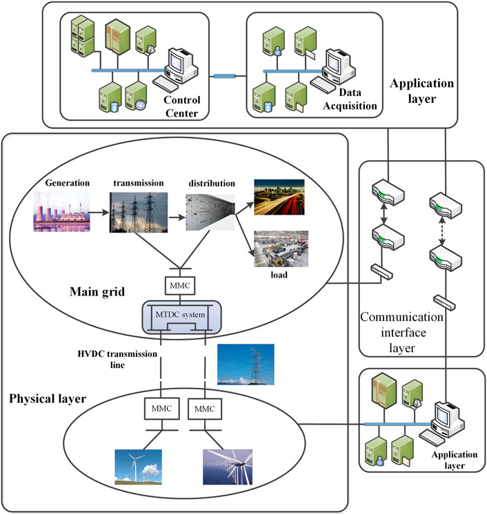
FIGURE 1. Cyber–physical power system with the MMC–MTDC main structure.
The application layer has many functions, such as human interaction, decision-making, and information analysis. The communication layer is responsible to send monitoring signals, control instructions, and other alerts (Liu et al., 2018). The stable operation of the main grid in the physical layer is of primary importance for the whole system. The MTDC system with the MMC converter has a complex dynamic performance; moreover, it has the generation equipment far away from the main grid. Therefore, the physical system must transmit information to the control center continuously.
In a cyber–physical power system, the power station does not execute the vital decisions; however, it carries only the data acquisition and the pre-processing tasks. The process of operation automation requires the control center to make decisions. Consequently, the reliability of a cyber–physical MTDC grid by large depends on the reliability of its control strategy. It not only adjusts the state variables of the controller to restore the stability of the physical layer after the fault occurs in different positions of the grid but also needs to be able to deal with the cyber uncertainties in the communication layer.
2.2 Analysis of MMC Operating Characteristics
A per-phase schematic of the MMC is shown in Figure 2. For the purpose of dynamic modeling, the dc bus can generally be considered to have pure capacitive characteristics, with capacitance Cd from the neutral to the positive and negative poles, that is, a pole-to-pole capacitance. VPCC represents the point of common coupling voltage of MMC–MTDC and AC grid, and the dc bus Vd is assumed to be balanced.
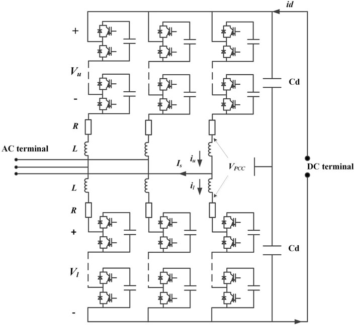
FIGURE 2. Circuit diagram.
For the arm voltage in the MMC circuit diagram, subscript u represents the upper arm and subscript l represents the lower arm. For the same, the current is defined as iu and il, respectively. For ease of control and calculation, the mentioned linear transformation is defined as
where Is represents the phase current in the AC side, Vs represents the internal electromotive force (EMF) of each phase arm driven, Is. Ic represents the average current of each phase arm which also contains any currents circulating between the phase legs, and Vc denotes the voltage that drives current Ic.
Converter operating principle is the foundation on which the control designs of the subsequent sections are built. Assuming that the dc bus is balanced, the circuits formed by the arms are given as follows:
Adding and subtracting these two relations, and introducing the output and circulating currents according to Eqs 2, 3, results in
2.3 Modeling of Generator And MTDC
2.3.1 Generator Model
In this article, the power generation equipment in the AC area of the main grid uses the well-known classical, fourth-order generator model, which is considered to be sufficiently accurate for stability. This article focuses on the electromechanical transient process of the generator rotor. The differential equations are
where δ is the angle of the rotor q axis of the generator relative to the synchronous rotating coordinate axis; ω is the angular speed of the generator rotor; H is the mechanical rotor inertia constant of the generator; Pm is the mechanical output power of the turbine; xd, xq denote d, q-axis reactance of generator; x' d, x' q is d, q-axis transient reactance; T′ d0, T′ q0 is d, q-axis time constant; and E′ d, E′ q is d, q component of transient voltage lagging behind reactance.
2.3.1 MTDC Model
Figure 3 represents a generic N-asynchronous AC area system connected through a MMC converter station and a multiport DC network. Each converter station is equipped with a DC voltage droop controller to connect the AC area. The multiterminal DC system is controlled by voltage droop, and each converter station has independent power and a DC voltage relationship curve.
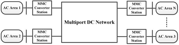
FIGURE 3. Framework of the MMC–MTDC model.
It combines the high-level control of an MMC controller to ensure the voltage stability of the DC network and the power injected into AC area N from the MTDC grid. In this model, the power flow of the AC and DC systems can be calculated separately.
The power system is represented by a system of differential algebraic equations:
where X is the state vector, Y is the algebraic vector, and P is the parameter vector. In this article, the set of differential equations F consists of the dynamic equations of the generators, while the algebraic equations contain the power flow equations and the stator current equations of the generators.
The MATPOWER is utilized for the load power flow analysis. The resulting augmented bus admittance matrix is calculated and constructed, and the initial conditions of the generator are calculated after the power flow converges (Zimmerman and Gan, 2016). If the system is in the steady state, then the main loop is started. The set of differential equations F is integral to solve the set of algebraic equations G. If an event occurs, the augmented bus admittance matrix and the algebraic equations G consist of the network equations, and stator current equations are reconfigured until the system reaches a new equilibrium or is away from equilibrium.
In this model, the modified Euler method is used to solve the differential equations, which is often used in power system analysis software packages. The variables are sent to the signal receivers in all parts of the power system, and the operation state is adjusted. At the same time, the power grid control system takes the values of Y, X changed or hold the unchanged state as the input value for the next iteration step until the end of the simulation time.
2.4 Cyber Signal Transmission Modeling
The signal transmission of a cyber–physical power system is expressed as a general network control system (NCS) problem considering network delay, packet loss, etc. Figure 4 shows the entire signal transmission process of the MMC and AC system and the closed-loop network control system. As shown in Figure 4, the first step is to measure data by sensors on each given bus at each control interval. A wide-area measurement system (WAMS) samples signals such as voltage and current at a fixed sampling interval, and then packs the sampled digital signals into packets, which are transmitted to the corresponding controller along different communication network paths and are utilized to generate control signals after processing at the front end of the controller. The reference control signal is transmitted to the corresponding actuator to realize the closed-loop control and stability support for the power system.
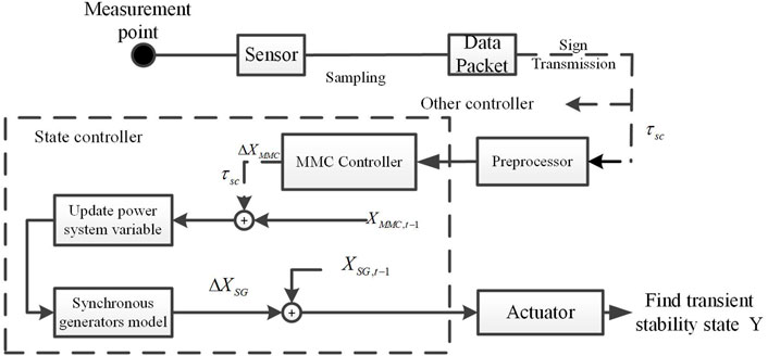
FIGURE 4. Signal transmission process of the cyber–physical system with the MMC.
The communication network plays a vital role in the closed-loop control process. However, network uncertainties such as network delay and packet loss may happen during signal transmission. These network defects will affect the quality of signal accuracy; moreover, they affect the transient stability of the power system. Specifically, when a communication delay occurs, the signal received by the controller at kth time is not the real-time corresponding signal transmitted by the sensor at k time but the non-corresponding signal due to the network delay of the forward channel. The delay in the signal acquisition results in the effective performance of the controller strategy. Moreover, the network uncertainty also exists in the feedback communication channel from the controller to the actuator. In this article, only the communication delay in the process of long-distance signal transmission channel is considered. It is need of the hour to develop a model considering the network delay in an MMC–MTDC system and design the corresponding control strategy to compensate it.
3 Proposed Hierarchical Adaptive Control Strategy
The overall control scheme of the MMC can be split into DC voltage control (VC) or a power transmission (Qin and Saeedifard, 2012), and internal average capacitor voltage control (Hagiwara and Akagi, 2009) (see Figure 5). The power transfer to the grid is controlled by the AC current. The average capacitor voltage is controlled by the corresponding circulating current in each phase (Pou et al., 2015). The resulting three phase output voltage references are translated into upper and lower arm voltages, respectively. The modulating and balancing blocks are finally used to create the gate signals, with an equal power distribution among the submodule (Hahn et al., 2018), (Fan et al., 2015). A power dq-transformation is used with ideal PLL. Furthermore, no details of the circulating current control, modulation, and balancing are provided since these dynamics are not included in the transient stability improvement.
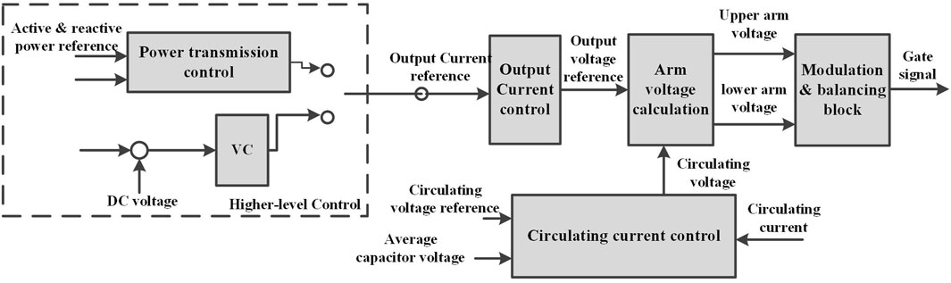
FIGURE 5. Overview of an MMC cascade control system.
In this section, the hierarchical adaptive control strategy for improving the stability of the cyber–physical grid in complex operating conditions is introduced. The proposed theory is divided into two parts: The first part introduces the traditional process for output current reference value. Second, a modified controlled strategy is proposed. The second part puts forward the solution when the power system fault causes the cyber communication layer problem.
Since zero-sequence components of voltage normally can be disregarded, it is possible to reduce a three-phase system to an equivalent two-phase system. The phase quantities thereof, denoted with the subscripts α and β, respectively, are 90° phase shifted. It is convenient to consider the equivalent two-phase system as projected on the αβ plane, whose real and imaginary axes, respectively, represent the α and β quantities. Complex two-phase representation V = vα + jvβ is also known as the Clarke transformation.
For ease of control, an MMC controller can use the α–β decoupling method to find α and β components of the output current reference, respectively, in a higher-level control. The cascade control structure in this article is also based on αβ components.
3.1 The Original Calculation Method in Higher-Level Control
The basic calculation principle of the output current reference is based on higher-level control in Figure 5. From this strategy, different control strategies can be derived. To produce the output current reference signal, DC voltage link is needed; PCC voltage and output active power are also required. So the original method controls the decoupled output current components separately, just like the control dq component. First, initial state quantity xdc and state increment dxdc are calculated as follows:
So for the α component of the output-current reference, it can be approximately obtained as follows:
where Pd and P are the input active power reference and measurement value in DC side, respectively. It can be clearly seen that when the DC voltage returns to the rated value after the system state changes dynamically, the α component of the output current also reaches a new steady state. KI and Kp are the controller gains. The high-level control adjusts the output current of the MMC through the parameters of the MTDC transmission system.
Similarly, the interaction between the β component of the output current and the PCC voltage is given as follows:
When system line or node fault occurs, causing a low voltage incident, reactive power injection in a time interval is needed to realize “low voltage ride through capability.” Thus, the reference of the output current’s β component is given as follows:
However, it is validated by performing a large number of simulations that the rectified converter does not transmit stable power under complex operating conditions. The DC-bus energy Wd deviates from its stable value whenever a node failure occurs in the power system; moreover, state quantity xdc also deviates from the steady-state value when a fault occurs on a significant node. This makes the power system difficult to restore to the stable state. The controller needs to adjust the parameters Kp and KI in the optimal time to make the output current reference stable when the topology of the power system changes. While the same control parameters are used for the fault in different positions of the power system, the system variables will deviate from the normal operating conditions or be in a state of continuous oscillation. Thus, in a large cyber–physical grid, for stability problems that may occur at an unidentified location and time, which are caused by the physical layer itself or the cyber layer, this control strategy is obviously not sufficient for wide adoption.
3.2 The First Stage of the Proposed Control Strategy
This article aimed at improving the drawbacks of the aforementioned output current reference calculation scheme which does not have a stable higher-level controller. Variable xdc in the aforementioned method has many possible steady-state values in the same physical layer of the grid topology, so this is not suitable for controller input. This article attempts to find an initial term in the high-level control which is different from xdc and has the tendency to return to the original value under any circumstances, to improve the accuracy of the MMC α component of the output current reference and ultimately improve system stability. Without reducing the number of input signals, we used more accurate output power of rectifier Psd as the new controller state.
The equation of Psd is given as follows:
In this way, the increment of state could be calculated as follows:
Correspondingly, the reference calculation method of the α component of output current is adjusted as follows:
We define Psd as the new state variable because it has the tendency to return to the stability point which is not possible with the xdc mentioned in the previous strategy. Moreover, when the system is stabilized, Psd returns to the initial rating, so it is logical and correct for us to define Psd as an input to the high-level controller. This also enables the reference value of the output current to get a new steady-state value. The second reason is improving the relevance of Is_α and Is_β; this will make the MMC’s control structure more complex and more adaptive to different operating conditions. It also speeds up the recovery of converter active output power during the low voltage events.
3.3 The Second Stage of the Proposed Hierarchical Control
The main goal of this part is to consider the existence of network uncertainty and design an optimal output current reference value calculation scheme for transient stability under MMC control. For the accurate performance of the control strategy, cascade control needs to ensure its own safe operation and output signals accurate enough after the event and delay occurs.
The communication delay problem of CPPS in this article is that the signal to the MMC controller does not correspond with the fault event. Assuming an information packet S needed to be transmitted from the source to the destination, expressed as S[Sin(t),k] shown in Figure 6, the time delay is not constant, but stochastic in nature, and it usually follows the exponential distribution verified by practical experiments in the study by Park and Lee (2001) and Tipsuwan and Chow (2004). In this article, the delay time is taken as the sample maximum. Once the delay time reaches a certain limit, the state signal mismatch will accumulate to the extent that the system cannot return to stability. The delay time is proportional to the distance of the line between the hardware; moreover, mitigation of the unbalancing caused by the signal mismatch during the occurrence of a fault is the key to solving the communication delay problem.
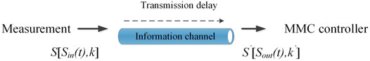
FIGURE 6. Information transmission process through the channel.
In order to solve this problem, an adaptive signal compensation scheme based on the output current reference considering network delay and solver algorithm is proposed. We extract the αβ component of the PCC voltage in the output signal as feedback and compare the corresponding value from the input signal to obtain compensation [Δα; Δβ]. We define the compensation signal of the proposed output current reference calculation method as COMP. It is obtained by the following:
where K = [k1; k2]. k1 and k2 represent the compensation gains. It can adjust the size of each gain to enhance (or weaken) the effect of the corresponding compensation signal on the system. The value with subscripts n+1 represents the output of the controller at the previous moment y(1)n+1. Correspondingly, the state with subscript t is the input of the controller at the next iteration. After adding the compensation signal, the new output current reference calculation method is expressed as follows:
From Eqs 27–29, the compensation values act with the delayed input signal to find the output current in the high-level control, and reduce the error response of the controller caused by the delay signal, thus reducing the adverse effects on the system by flexibly adjusting the higher-level input signal of the controller. The proposed calculation method not only considers the control regulation of the active power by the high-level control but also considers the PCC voltage influence in the β component (most critical) of the output current, thus increasing the rate of the low voltage ride through response and finally affecting the transient stability of the power grid system.
When a fault occurs, the fault current will carry the information to the data center, and the problem of the network delay and packet loss in the cyber system will inevitably mean the cyber–physical disturbance is quantifiable by the distance of network communication and the packet loss rate. If the network delay or packet loss makes the signal COMP become large, the second stage of the proposed control strategy automatically makes the compensation signal transmitted to the controller so as to reduce the disturbance to the operation of the physical information system. Meanwhile, we also need to keep track of the timing of the compensation mechanism. In this article, when the difference between the voltage signals sent by the main application layer to the remote end exceeds 0.1% of rating, we consider that a communication delay in the system occurs; moreover, the compensation scheme of the MMC–MTDC controller needs to be triggered. After the fault is cleared, the value of the system operation tends to be stable, and the influence of network delay and packet loss is very small, so the COMP value can be ignored.
However, because of the ODE (ordinary differential equation) solvers used in the simulation model, it is necessary to set the compensation signal “COMP” to zero in the second stage in order to avoid “over-regulation.” The second stage of the hierarchical control strategy model to solve the problem of communication delay is presented in Figure 7.
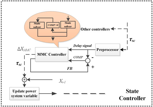
FIGURE 7. Proposed method of the state controller for the cyber–physical system.
Here, the output reference current calculation-based control strategy on improving the transient stability of the cyber–physical MMC–MTDC system has been established.
4 Case Studies
A comparative analysis is conducted between the original and proposed control schemes, and its feasibility is examined by considering the communication delay problem. In this article, the time-domain simulation method is used to analyze the stability of the system. In the time-domain simulation method, the differential algebraic equations which describe the system’s transient process are numerically integrated to gradually obtain the values of system variables which change with time, and then judge the transient stability of the system according to the drawn curves.
A modified IEEE 9-bus system (Figure 8) containing an MMC–MTDC is simulated to validate the proposed strategy. AC2 and AC3 are the sending ends, while AC1 is the receiving end. The DC ports are connected to buses 2, 10, and 8 through MMCs 1, 2, and 3, respectively. Since the HVDC transmission system has the function of blocking AC faults, in the case of AC faults discussed in this article, we need not study the transient processes of AC2 and AC3, but only the transients of AC1 and MTDC dynamics. The parameters of the grid MMC are shown in Table 1. The machine performance will affect the simulation time. The simulations in this article were performed using MATLAB R2014a on a PC with an i7-6700 3.4 GHz CPU and 32 GB RAM.
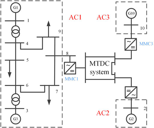
FIGURE 8. Framework of the MMC–MTDC test model.
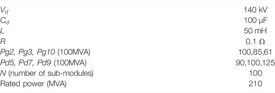
TABLE 1. Important parameters of grid and MMC.
4.1 Physical Layer Fault
4.1.1 Original Control Strategy
In the proposed control strategy, control parameters Kp1, Kp2, Kd1, and Kd2 of the higher level are equal to 400, 700, 40, and 40, respectively. In this article, the behavior of the generator and the MTDC system are used to study the effects of control strategies. This section describes two different contingencies: 1) a three-phase grounding fault occurred on bus 5; 2) the same three-phase grounding fault at bus 6 which is near the generator bus. The three-phase grounding fault which is common and harmful in real life is assumed to happen at one bus when t = 1.1 s and is cleared at t = 1.15 s. Figures 9A–D gives the dynamic performance of the generator and MMC after two contingencies.
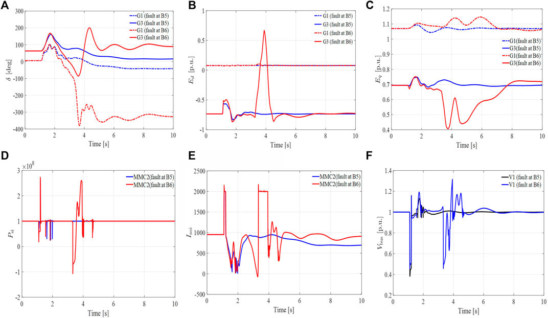
FIGURE 9. Dynamic responses of the generator and the MMC–MTDC in an original control method. (A) The rotor angles of generator 1,3 in degrees. (B) d-axis component of the voltage 1,3 behind transient reactance in p.u. (C) q-axis component of the voltage 1,3 behind transient reactance in p.u. (D) Active power of MMC2. (E) α component of the MMC2 output-current. (F) Voltage of bus 1 in main grid.
The first contingency simulation results show that the generator and the MMC–MTDC system states can return to stability quickly after the fault is cleared. However, when the same fault is applied to bus 6, the rotor angle of generators 1 and 3 deviated significantly from their normal operating states. Although the d, q-axis component of the voltage 3 behind transient reactance restores to its initial state, there is an obvious swell that is not acceptable for the safe operation of the system. The original control strategy is not adaptable to the complex cyber–physical system because the output active power fluctuation of MMC2 takes approximately 5 s to reach a steady state (Figure 9D). This creates a domino effect and drives the state variable xdc on bus 6 to instability. Since xdc controls the output reference current, instable xdc drives the output reference current to become unstable. As a result, the α component of MMC2 output current takes a long time to reach the steady state which moves the system to permanent instability as shown in Figure 9E.
4.1.2 Proposed Control Strategy
In this part, the proposed control in the higher level is applied to verify its effectiveness. Unlike the original control method, new control parameters can be easily set. In this case, Kp1, Kp2, Kd1, and Kd2 are 200, 200, 50, and 50, respectively. Validation is done by performing five simulations. The first two simulations have the same fault scenarios as described in the former sections. The accuracy of the presented scheme for the MMC–MTDC system operation is analyzed by three additional faults applied to the same model: 3) bus 9 takes a longer duration of failure while taking 0.7 s to clear; 4) the same grounding fault occurs at bus 8 which connects with the MMC–MTDC system. The performance of the generator and the MMC–MTDC state are shown as given in Figures 10A–I. To facilitate observation, the rotor angles and voltage of generators 1 and 3 are divided into two figures.
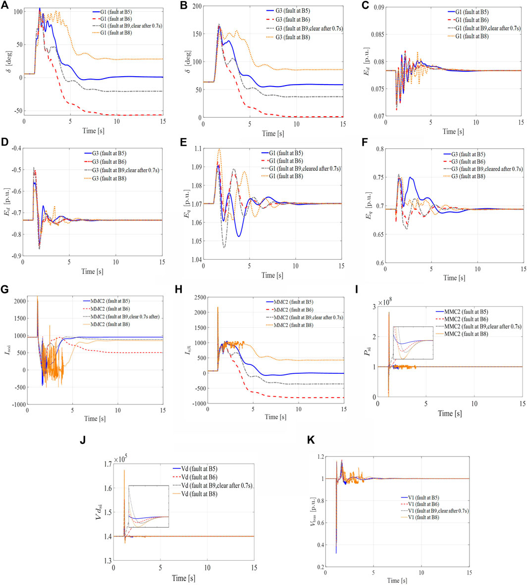
FIGURE 10. Dynamic responses of the generator and the MMC–MTDC in case 2: (A) The rotor angle of generator 1 in degrees. (B) The rotor angle of generator 3 in degrees. (C) d-axis component of the voltage 1 behind transient reactance in p.u. (D) d-axis component of the voltage 3 behind transient reactance in p.u. (E) q-axis component of the voltage 1 behind transient reactance in p.u. (F) q-axis component of the voltage 3 behind transient reactance in p.u. (G) α component of the output-current in MMC2. (H) β component of the output-current in MMC2. (I) Active output power of MMC2. (J) DC Voltage of MTDC system. (K) Voltage of bus 1 in main grid.
The simulation results show that when the same fault incident occurs, the proposed hierarchical control strategy maintains stability which is not possible with the original scheme. The α, β components of the output current are also shown in Figures 10G,H. The results show that unlike original state values, the new state variable helps in quick restoration of the stability of the MMC2 output current. Figure 10J shows the DC voltage of the MMC–MTDC during operation; it can be seen that the three-phase grounding fault has a short adverse effect in this control strategy. And the voltage of slack bus under faults is shown in Figure 10K.
Two separate three-phase grounding faults are applied at different buses within a short time duration. The fault is applied to bus 7 at t = 1.5 s and is cleared at 0.5 s later, and the same scenario is applied if the condition occurs at bus 9 when t = 3 s. The simulation results are given as follows.
Figures 11A–D show the behavior of the MMC–MTDC and AC system after two faults. During serious and complex faults, the state of the generator and the MMC–MTDC oscillates with the occurrence of faults. However, it quickly returns to a stable operating condition or the initial state.
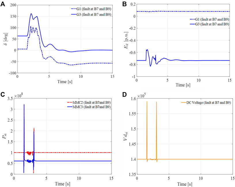
FIGURE 11. Dynamic responses of the generator and the MMC–MTDC. (A) The rotor angle of generator 3 in degrees. (B) d-axis component of the voltage 3 behind transient reactance in p.u. (C) Active power of MMC2. (D) DC Voltage of MTDC system.
In conclusion, with the proposed hierarchical control strategy, the system can return to a stable state in a short time under various fault scenarios. For the modified higher-level control of hierarchical controller input parameter Psd, the αβ component of the output current can reach a new equilibrium value after oscillation so that the rated operating value of the system remains unchanged. In all serious contingencies designed in the simulation, all generators can keep the rotor angle stable, and the voltage behind transient reactance Edq will remain unchanged. Therefore, this control strategy significantly improves the transient stability of the AC system with the MMC–MTDC under a physical layer fault.
4.2 Cyber Layer Fault: Communication Delay
A series of simulations are performed considering the proposed cyber–physical system with the MMC–MTDC model. A three-phase fault is introduced at 2.0 s for which a communication delay is observed. The main grid network transmits the new state variable’s signal to the remote MMC sending end that connects to the generators at nodes 2 and 10. A change signal is received by the MMC signal receiver at a sampling frequency of 200 calculation steps (0.02 s), and the MMC controller of the rectifier responds to the new input state and changes the running conditions of the generators. The controller sets to the new steady-state and continuously receives a signal with a 200-step delay thereafter.
In this case, a contingency analysis is performed to study the effect of communication delay on the MMC–MTDC system and the transient stability of the AC system. A three-phase grounding fault is introduced in the system at 2.0s and is cleared in 0.07s. In the presence of communication delays, with and without the proposed voltage compensation scheme, the dynamic process of the rotor angle, D-axis component of voltage 3, and MMC2 output active power are shown in Figures 12A–C, whereas the compensation signal of the hierarchical control strategy’s second stage during operation is shown in Figure 12D.
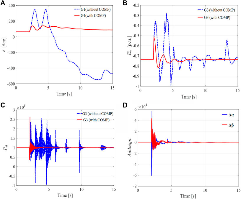
FIGURE 12. Dynamic responses of the generator and the MMC–MTDC and compensation signal of a single MMC controller after communication delay occurs. (A) The rotor angle of generator 3 in degrees. (B) d-axis component of the voltage 3 behind transient reactance in p.u. (C) Active power of MMC2. (D) The compensation signal acts on MMC2 controller.
In the presence of a network delay, the transient stability of the system is at stake (Figure 12). The phase angle of generator 3 has exceeded the rating (−360°), whereas the active power from the AC2 system oscillates violently for a long time. Compared with the results of using the proposed voltage compensation-based hierarchical adaptive control method, it is realized that the transient stability of the physical–cyber system under the cyber layer fault is greatly improved. From Figure 12D, it is evident that the signal COMP observes a first swell when the fault is introduced; however, it mitigates with time. The effect of the compensation mechanism on the MMC controller stops at about 12 s. Therefore, the results show that the proposed scheme can eliminate the adverse effects caused by communication delay and will not interfere with the system operation afterward.
5 Conclusion
In this article, voltage compensation-based hierarchical adaptive control for improving the transient stability of the cyber–physical MMC–MTDC system is presented. In the first stage of the control strategy, the transient stability of the MMC–MTDC physical layer system is improved; in the second stage, adverse effects of communication delay on the cyber–physical system stable operation are eliminated. Simulations are performed by modifying the IEEE-9 bus system with a three-terminal MTDC grid. The proposed strategy has a high tendency for practical application in the fields of the cyber–physical MMC–MTDC system in the future. The following conclusions are drawn from the theoretical analyses and model simulations:
1) The first stage of the hierarchical control modifies the higher-level control method ensuring the stability of the reference value of the output current in the case of large disturbance. Consequently, the MMC–MTDC grid’s transient stability is improved significantly.
2) Considering the potential risk of communication delay to power grid stability, the proposed voltage compensation scheme-based hierarchical control effectively ensures the accuracy of cascade control and improved the reliability of the cyber–physical system.
Therefore, the proposed hierarchical control can effectively improve the transient stability under fault events in cyber–physical MMC–MTDC systems.
Data Availability Statement
The original contributions presented in the study are included in the article/Supplementary Material; further inquiries can be directed to the corresponding authors.
Author Contributions
XW contributed to all aspects of this work and conducted data analysis. HJ, HW, and JP gave useful comments and suggestions to this work, and affect the process of the research. All authors reviewed the manuscript.
Funding
This study was supported by the Foundations of Shenzhen Science and Technology Innovation Committee under grants JCYJ20180305125407996, GJHZ20180928160212241, and JCYJ20190808165201648.
Conflict of Interest
The authors declare that the research was conducted in the absence of any commercial or financial relationships that could be construed as a potential conflict of interest.
Publisher’s Note
All claims expressed in this article are solely those of the authors and do not necessarily represent those of their affiliated organizations, or those of the publisher, the editors, and the reviewers. Any product that may be evaluated in this article, or claim that may be made by its manufacturer, is not guaranteed or endorsed by the publisher.
References
Chen, W., Zhu, X., Yao, L., Ning, G., Li, Y., Wang, Z., et al. (2016). A Novel Interline DC Power-Flow Controller (IDCPFC) for Meshed HVDC Grids. IEEE Trans. Power Deliv. 31, 1719–1727. doi:10.1109/TPWRD.2016.2547960
Duan, J., Xu, H., and Liu, W. (2018). Q-Learning-Based Damping Control of Wide-Area Power Systems under Cyber Uncertainties. IEEE Trans. Smart Grid 9, 6408–6418. doi:10.1109/TSG.2017.2711599
Eriksson, R. (2014). Coordinated Control of Multiterminal DC Grid Power Injections for Improved Rotor-Angle Stability Based on Lyapunov Theory. IEEE Trans. Power Deliv. 29, 1789–1797. doi:10.1109/TPWRD.2013.2293198
Fan, S., Zhang, K., Xiong, J., and Xue, Y. (2015). An Improved Control System for Modular Multilevel Converters with New Modulation Strategy and Voltage Balancing Control. IEEE Trans. Power Electron. 30, 358–371. doi:10.1109/TPEL.2014.2304969
Hagiwara, M., and Akagi, H. (2009). Control and Experiment of Pulsewidth-Modulated Modular Multilevel Converters. IEEE Trans. Power Electron. 24, 1737–1746. doi:10.1109/TPEL.2009.2014236
Hahn, F., Andresen, M., Buticchi, G., and Liserre, M. (2018). Thermal Analysis and Balancing for Modular Multilevel Converters in HVDC Applications. IEEE Trans. Power Electron. 33, 1985–1996. doi:10.1109/TPEL.2017.2691012
Huang, K., Li, Y., Zhang, X., Liu, L., Zhu, Y., and Meng, X. (2021). Research on Power Control Strategy of Household-Level Electric Power Router Based on Hybrid Energy Storage Droop Control. Prot. Control Mod. Power Syst. 6, 178–190. doi:10.1186/s41601-021-00190-2
Javed, R., Mustafa, G., Khan, A. Q., and Abid, M. (2018). Networked Control of a Power System: A Non-uniform Sampling Approach. Electr. Power Syst. Res. 161, 224–235. doi:10.1016/j.epsr.2018.04.014
Liu, W., Gong, Q., Han, H., Wang, Z., and Wang, L. (2018). Reliability Modeling and Evaluation of Active Cyber Physical Distribution System. IEEE Trans. Power Syst. 33, 7096–7108. doi:10.1109/TPWRS.2018.2854642
Oghorada, O., Zhang, L., Han, H., Esan, A., and Mao, M. (2021). Inter-cluster Voltage Balancing Control of a Delta Connected Modular Multilevel Cascaded Converter under Unbalanced Grid Voltage. Prot. Control Mod. Power Syst. 6, 289–299. doi:10.1186/s41601-021-00202-010.1186/s41601-021-00203-0
Park, J W., and Lee, J. M. (2001). Transmission Modeling and Simulation for Internet-Based Control. 27th Annu. Conf. IEEE Industrial Electron. Soc. 1, 165–169. doi:10.1109/IECON.2001.976473
Pou, J., Ceballos, S., Konstantinou, G., Agelidis, V. G., Picas, R., and Zaragoza, J. (2015). Circulating Current Injection Methods Based on Instantaneous Information for the Modular Multilevel Converter. IEEE Trans. Ind. Electron. 62, 777–788. doi:10.1109/TIE.2014.2336608
Qiang, G., Xi, Y., and Ye, L. (2018). “Circulating Current Suppressing and AC Faults Ride-Through Capability Analysis of Zhoushan MMC-MTDC System,” in Proc. IEEE Conf. on Energy Internet and Energy Syst Integra, Beijing, China, 20-22 Oct. 2018 (IEEE), 1–7. doi:10.1109/EI2.2018.8582364
Qin, J., and Saeedifard, M. (2012). Predictive Control of a Modular Multilevel Converter for a Back-To-Back HVDC System. IEEE Trans. Power Deliv. 27, 1538–1547. doi:10.1109/TPWRD.2012.2191577
Sau-Bassols, J., Ferrer-San-Jose, R., Prieto-Araujo, E., and Gomis-Bellmunt, O. (2020). Multiport Interline Current Flow Controller for Meshed HVDC Grids. IEEE Trans. Ind. Electron. 67, 5467–5478. doi:10.1109/TIE.2019.2934058
Teixeira Pinto, R., Bauer, P., Rodrigues, S. F., Wiggelinkhuizen, E. J., Pierik, J., and Ferreira, B. (2013). A Novel Distributed Direct-Voltage Control Strategy for Grid Integration of Offshore Wind Energy Systems through MTDC Network. IEEE Trans. Ind. Electron. 60, 2429–2441. doi:10.1109/TIE.2012.2216239
Tipsuwan, Y., and Chow, M.-Y. (2004). Gain Scheduler Middleware: A Methodology to Enable Existing Controllers for Networked Control and Teleoperation-Part I: Networked Control. IEEE Trans. Ind. Electron. 51, 1218–1227. doi:10.1109/TIE.2004.837866
Vellaithurai, C., Srivastava, A., Zonouz, S., and Berthier, R. (2015). CPindex: Cyber-Physical Vulnerability Assessment for Power-Grid Infrastructures. IEEE Trans. Smart Grid 6, 566–575. doi:10.1109/TSG.2014.2372315
Wang, C., Zhang, T., Luo, F., Li, F., and Liu, Y. (2019). Impacts of Cyber System on Microgrid Operational Reliability. IEEE Trans. Smart Grid 10, 105–115. doi:10.1109/ICMLC.2009.521236510.1109/tsg.2017.2732484
Wang, H., Ruan, J., Ma, Z., Zhou, B., Fu, X., and Cao, G. (2019). Deep Learning Aided Interval State Prediction for Improving Cyber Security in Energy Internet. Energy 174, 1292–1304. doi:10.1016/j.energy.2019.03.009
Wang, H., Ruan, J., Zhou, B., Li, C., Wu, Q., Raza, M. Q., et al. (2019). Dynamic Data Injection Attack Detection of Cyber Physical Power Systems with Uncertainties. IEEE Trans. Ind. Inf. 15, 5505–5518. doi:10.1109/TII.2019.2902163
Wang, P., Ashok, A., and Govindarasu, M. (2015). “Cyber-physical Risk Assessment for Smart Grid System Protection Scheme,” in Proceeding of the 2015 IEEE Power & Energy Society General Meeting, Denver, CO, USA, 26-30 July 2015 (IEEE), 1–5. doi:10.1109/TSG.2014.2387381
Wang, Y., Yuan, Z., and Fu, J. (2016). A Novel Strategy on Smooth Connection of an Offline MMC Station into MTDC Systems. IEEE Trans. Power Deliv. 31, 568–574. doi:10.1109/TPWRD.2015.2437393
Wen, X., Peng, J., Aziz, S., and Jiang, H. (2020). PCC Voltage Compensation Scheme of MMC-MTDC System for Transient Stability Enhancement under Communication Delay. IEEE Access 8, 187713–187720. doi:10.1109/ACCESS.2020.3026097
Xin, S., Guo, Q., Sun, H., Zhang, B., Wang, J., and Chen, C. (2015). Cyber-physical Modeling and Cyber-Contingency Assessment of Hierarchical Control Systems. IEEE Trans. Smart Grid 6, 2375–2385. doi:10.1109/TSG.2014.2387381
Zhang, J., Cui, M., and He, Y. (2020). Robustness and Adaptability Analysis for Equivalent Model of Doubly Fed Induction Generator Wind Farm Using Measured Data. Appl. Energy 261, 114362. doi:10.1016/j.apenergy.2019.114362
Zhang, S., Zou, G., Wang, C., Li, J., and Xu, B. (2020). A Non-unit Boundary Protection of DC Line for MMC-MTDC Grids. Int. J. Electr. Power & Energy Syst. 116, 105538. doi:10.1016/j.ijepes.2019.105538
Zhang, Y., Cong, W., Li, G., Sun, K., and Zhang, Y. (2020). Single-ended MMC-MTDC Line Protection Based on Dual-Frequency Amplitude Ratio of Traveling Wave. Electr. Power Syst. Res. 189, 106808. doi:10.1016/j.epsr.2020.106808
Zhao, T., Wang, D., Lu, D., Zeng, Y., and Liu, Y. (2015). “A Risk Assessment Method for Cascading Failure Caused by Electric Cyber-Physical System (ECPS),” in Proceeding of the 2015 5th International Conference on Electric Utility Deregulation and Restructuring and Power Technologies, Changsha, China, 26-29 Nov. 2015 (IEEE), 787–791. doi:10.1109/DRPT.2015.7432333
Zhen-Dong Zhao, Z., Lou, Y.-Y., Jun-Hong Ni, J., and Jing Zhang, J. (2009). “RBF-SVM and its Application on Reliability Evaluation of Electric Power System Communication Network,” in Proceeding of the 2009 International Conference on Machine Learning and Cybernetics, Baoding, China, 12-15 July 2009 (IEEE), 1188–1193. doi:10.1109/ICMLC.2009.5212365
Zimmerman, R., and Gan, D. (2016). MATPOWER: A Matlab Power System Simulation Package. [Online]. Available: http://www/pserc.cornell.edu.
Keywords: multiterminal direct current (MTDC), modular multilevel converter, cyber–physical power system, hierarchical control, transient stability
Citation: Wen X, Wu T, Jiang H, Peng J and Wang H (2022) Hierarchical Adaptive Control of the Cyber–Physical Power System With MMC-MTDC for Transient Stability Improvement. Front. Energy Res. 10:929568. doi: 10.3389/fenrg.2022.929568
Received: 27 April 2022; Accepted: 23 May 2022;
Published: 08 July 2022.
Edited by:
Xueqian Fu, China Agricultural University, ChinaCopyright © 2022 Wen, Wu, Jiang, Peng and Wang. This is an open-access article distributed under the terms of the Creative Commons Attribution License (CC BY). The use, distribution or reproduction in other forums is permitted, provided the original author(s) and the copyright owner(s) are credited and that the original publication in this journal is cited, in accordance with accepted academic practice. No use, distribution or reproduction is permitted which does not comply with these terms.
*Correspondence: Ting Wu, dHd1OTIwQGhvdG1haWwuY29t; Hui Jiang, aHVpamlhbmdAc3p1LmVkdS5jbg==