 Mingsheng Chen
 Panpan Xiao
 Hao Zhou2
 Chun Bao Li
- 1Key Laboratory of High Performance Ship Technology, Ministry of Education, Wuhan University of Technology, Wuhan, China
- 2School of Naval Architecture, Ocean and Energy Power Engineering, Wuhan University of Technology, Wuhan, China
- 3Sanya Science and Education Innovation Park of Wuhan University of Technology, Sanya, China
- 4Department of Engineering, Poly Changda Engineering Co. Ltd., Guangzhou, China
The offshore wind power exploitation has experienced rapid development in recent years and has gradually moved into deeper waters with the floating wind turbine technology getting mature. Due to the strong concurrence of the wind and wave power in offshore sites, the idea of combined utilization of wind and wave power by one integrated device has attracted tremendous interests worldwide and a number of concepts and designs have been proposed. This article describes a novel integrated floating wind-wave generation platform (FWWP) consisting of a DeepCwind semi-submersible floating offshore wind turbine (FOWT) and a point absorber wave energy convertor (PAWEC). Three models including the single PAWEC, single FOWT, and FWWP are considered to investigate the feasibility of the FWWP and its advantages over the single device. Hydrodynamic analyses are first conducted using the potential flow code AQWA with the viscous correction to investigate the hydrodynamic interactions effect of the integrated model. Then, a fully coupled model for the FWWP is established by calling OpenFAST in AQWA using the F2A method. The accuracy of the established coupled model is firstly validated with OpenFAST for analysing the dynamics of the single FOWT. Finally, fully coupled analyses of the FWWP are carried out for both regular and irregular waves in the operational sea-states. The coupled dynamics and wind and wave power generation of the FWWP are compared with those of the single PAWEC and FOWT for both the regular and irregular waves.
Introduction
In recent years, the development of offshore renewable energy dominated by the offshore wind power exploitation has entered a golden age of rapid development. According to the latest GWEC report (GWEC, 2022), the global accumulated installation capacity of offshore wind turbines has reached 57.2 GW by the end of 2021, which has increased by 62% compared with that of 2020. With the available shallow waters for offshore fixed wind turbines being more and more occupied, the floating offshore wind turbine (FOWT) has become an inevitable trend for the further development of offshore wind resources in deep waters (Wu et al., 2019). Meanwhile, offshore wind and wave energies have strong symbiosis, which signifies that abundant wind energies are often accompanied by ample wave energy resources. However, different from the offshore wind energy exploitation, wave energy has not yet been exploited at large commercialized scale as limited by its high construction and maintenance costs, unstable power generation, and low reliability (Zhang et al., 2021). The FOWT technology has been well proven to be a reliable means of exploiting wind power in deep waters, with several commercial floating wind farms being operated in Europe including the Hywind Scotland, WindFloat Atlantic, and Kincardine Scotland projects. A total of 57 MW floating wind capacity was installed in 2021, including one floating wind farm in the UK and two demonstration floating wind turbines in Norway and China, respectively (GWEC, 2022). However, the high costs associated with the mooring system and long-distance subsea power cables may make FOWT technology cost ineffective in deep waters where there are denser and more stable wind energy resources. Therefore, the concept of combined utilization of the wind and wave energies in deep waters, which integrates the wave energy converter (WEC) with an FOWT, has become one of the hottest research topics in the area of offshore renewable energy development (McTiernan and Sharman, 2020). A detailed review of the combined wind-wave power generation technologies can be found in the work of Pérez-Collazo et al. (2015) and McTiernan and Sharman (2020). Compared with the concept of integrating WECs with fixed offshore wind turbines, the concept of floating wind-wave hybrid system is relatively new, which has started to be seriously considered with the emergence of floating wind turbine prototypes in recent years. As the deep waters have more stable wind power and denser wave energy, combined utilization of the wind and wave power by using the integrated floating wind-wave power generation platform (FWWP) may inherently have some advantages with the growing maturity of the FOWT technology and may inevitably encounter with increased system complexities compared with its counterpart in shallow waters.
The advantages of the FWWP mainly lie in the following: 1) the mooring system, electricity transmission system, and other components of WECs can be shared with an existing FOWT, which could help to reduce the total installation, operation, and maintenance costs; 2) the integration of WECs with an FOWT may reduce the dynamics of the FOWT through proper arrangement of the WECs such that they behave like a damper system to the FOWT. In addition, due to the possible hydrodynamic interactions between the WECs and FOWT, the wave power generation of the integrated device may be significantly enhanced under certain specific sea-states (Chen et al., 2020; Zhu et al., 2020).
Based on the existing foundation concepts of FOWT such as the Spar, TLP, and semi-submersible, various designs and concepts of integrated FWWPs have been proposed in the last decade. In this regard, American Marine Innovation and Technology proposed two concepts that integrate the WindFloat semi-submersible FOWT with oscillating water column (OWC) devices (Aubault et al., 2011) and with a point absorber wave energy converter (PAWEC) (Peiffer et al., 2011), respectively. Based on the design of the DeepCwind semi-submersible FOWT, Chen et al. (2020) proposed a novel FWWP in which a PAWEC is placed at the centre of the waterplane area enclosed by the vertical columns of the DeepCwind semi-submersible foundation. For this design, the power take-off (PTO) system of the PAWEC is mounted onto the top braces of the semi-submersible foundation such that the relative heaving motions between the PAWEC and semi-submersible foundation are utilised to convert wave energy into electricity. Scholars from the Norwegian University of Science and Technology also proposed different design concepts for the integrations of various FOWTs and WECs, such as the integration of a Spar-type FOWT with an oscillating floater WEC (Muliawan et al., 2012) and the integration of a semi-submersible-type FOWT with the flap-type WECs (Luan et al., 2014). In addition, there are also some novel concepts that integrate multiple wind turbine generators and WECs within one supporting platform, such as the Poseidon P80 designed by Floating Power Plant A/S (FPP) of Denmark (Izquierdo-Pérez et al., 2020), W2Power proposed by Pelagic Power of Norway (McTiernan and Sharman, 2020), and the wind-wave hybrid platform concept proposed by KRISO (Lee et al., 2018). Although plenty of concepts of FWWP have been proposed, numerically modelled, and tested and even some concepts have entered the sea-trial test stage, it is still difficult to judge which concept is more promising. In addition, the dynamic coupling mechanism between the WECs and FOWT has not yet been fully understood.
The FWWP generally consists of an FOWT, WECs, PTO system, mooring system, and other modules, which may involve complex hydrodynamic interactions and dynamic coupling between the WECs and FOWT. The floating substructure of the FOWT is a key factor to be considered in the design of an FWWP, which may govern the selection of the types of WEC and number of WECs to be integrated. Eventually, it may determine the performance of the FWWP. For semi-submersible platforms, the “near-trapping” phenomenon caused by the hydrodynamic interactions between the multiple columns of the floating substructure may increase the wave amplitudes of the waterplane area enclosed by the columns (Walker et al., 2008), which may, therefore, enhance the power generation of WECs placed in-between the semi-submersible columns. In addition, the PTO system also has significant influences on the dynamic coupling between the WECs and FOWT, and optimised performances of the FWWP may be achieved by appropriately selecting the PTO parameters and control strategies. Many studies have illustrated that WECs can help to reduce the dynamics of the FOWT in an FWWP system provided that the PTO control strategies are appropriately applied (Karimirad and Koushan, 2016; Zhu et al., 2020; Gaspar et al., 2021).
The dynamics and performances of a single FOWT and WEC can be analysed by using OpenFAST (Jonkman and Buhl, 2005) and WEC-Sim (Ruehl et al., 2014), respectively. However, compared with the single wind/wave device, the analysis of the FWWP lacks for a standard and widely recognised simulation tool. For the analysis of the FOWT, an aero–hydro–servo–elastic–mooring-coupled model is generally needed, in which the aero–servo–elastic coupling is the unique feature of the FOWT. For the FWWP, due to the introduction of WECs, the multi-body hydrodynamic interactions, mechanical coupling between the FOWT and WECs via the PTO system, and the PTO control strategy are the new features that need to be coupled together with the dynamics of the FOWT. Therefore, one common approach to analyse the dynamics and performance of an FWWP is to extend the capability of the well-established time-domain model for dynamic analysis of the floating bodies to account for the aero–servo–elastic coupling effects. By this approach, the PTO system can be modelled as either a linear or nonlinear spring-damper system, and an additional PTO control scheme can be developed and added into the time-domain model. In this regard, MARINTEK proposed an analysis method based on the existing SIMO and RIFLEX modules and established an aero–hydro–servo–elastic coupling model, in which the SIMO module is used to calculate the hydrodynamic loads and the RIFLEX module is extended to account for the aerodynamic loads on elastic structural members by adopting the blade element momentum theory. Besides, the PTO system is generally simplified as a linear spring-damper system. Based on this method, Muliawan et al. (2012) and Luan et al. (2014) carried out a lot of work to analyse the coupled dynamics of various types of FWWPs. Karimirad and Koushan (2016) applied this method to investigate the feasibility of integrating the Wavestar-type WEC with a Spar-type FOWT and considered the effects of the PTO system parameters on the dynamics of the FWWP and on the power generations of the WEC and wind turbine. Their analyses revealed that the influence of the WEC on the dynamics of the FOWT can be reduced to the maximum if the PTO system is appropriately designed and the power generation performance of the WEC can be enhanced while maintaining that of the FOWT. In addition to the aforementioned method, with certain simplifications, many researchers also applied the frequency/time-domain simulation package AQWA (Ansys, 2016) to analyse the coupled dynamics of the FWWP. This package has been widely used in analysing the dynamics of multiple floaters and WECs (Chen et al., 2021a; Chen et al., 2021b). By ignoring the aero–servo–elastic coupling effects of the upper wind turbine structure, Chen et al. (2020) applied AQWA to analyse the hydrodynamic interactions between the PAWEC and semi-submersible-type FOWT based on their own FWWP concept. By considering only the heaving motions of the FWWP, they performed time-domain simulations using AQWA by modelling the PTO system as a linear spring-damper system and found that it may enhance the power generation of the PAWEC under certain wave conditions by placing the PAWEC at the centre of the semi-submersible foundation. Ren et al. (2020) established a numerical model based on AQWA to investigate the dynamics of a TLP–WEC-combined FWWP under the operational sea-states. Their model ignores the effects of elastic behaviour of the blades and tower structures, and the aerodynamic loads on the wind turbine rotor were simplified as equivalent thrusts and bending moments, which are imported to the AQWA model by using the User-force function of AQWA to establish a direct coupling between the simplified equivalent aerodynamic loads with the wind turbine platform motions. Their numerical results were compared with the experimental results and good agreement was achieved, which may imply that the ignorance of the elastic behaviour of the blades and tower structures may not have significant influences on the performances of the FWWP. Based on AQWA, Si et al. (2021) established a coupled aero–hydro–servo–PTO–mooring time-domain model for analysing the performances of the DeepCwind–Wavestar-combined (DWC) platform. In their model, the aerodynamic loads on the wind turbine generators were calculated based on the Blade Element Momentum (BEM) theory and were coupled with AQWA using its User-defined function, but the elastic behaviour of the blades and tower structures was ignored. In addition, they incorporated the PTO control strategies into the AQWA model to investigate the impact of PTO control on the dynamics and power generations of the DWC FWWP. The aforementioned studies of the FWWP based on the use of AQWA involve certain simplifications, which are not fully coupled simulations of the FWWP. Yang et al. (2020) developed a fully coupled aero–hydro–servo–elastic–mooring model based on AQWA for analysing the performance of an integrated floating energy system. In their model, the aero–servo–elastic coupled simulation capability of OpenFAST is implemented into AQWA by its User-defined function, which is invoked by AQWA’s time-domain solver at each time step. In this way, the kinematics and kinetics of the wind turbine solved by OpenFAST are instantaneously coupled with the platform and mooring system dynamics solved in AQWA. The accuracy of their model was validated with experimental results and numerical simulations by OpenFAST. This approach is known as the F2A method and enables AQWA to be capable of performing fully coupled analysis of both the FOWT and FWWP. The F2A method was subsequently used by Li et al. (2021) to analyse the wind-wave coupling effects on the dynamics of an FWWP consisting of a braceless semi-submersible-type FOWT and a heave-type WEC.
In this study, the FWWP consisting of a DeepCwind semi-submersible FOWT and a PAWEC, proposed by Chen et al. (2020), is analysed to investigate the dynamics and power generations of this concept in operational sea-states. Both frequency- and time-domain simulations are carried out in AQWA for three models including the single PAWEC, single FOWT, and FWWP. In the frequency-domain model, only the heaving motions are considered since only the heaving motions are used to transfer wave energy into electricity. Based on the frequency-domain model, the complex hydrodynamic interaction and its effects on the wave power generation of the FWWP are analysed. The F2A method developed by Yang et al. (2020) is applied here to establish a fully coupled time-domain model for the FWWP by using AQWA. The accuracy of the coupled model is validated with OpenFAST for analysing the dynamics of a single FOWT. Finally, fully coupled time-domain analyses are carried out to investigate the dynamics and power generations of the FWWP in different operational sea-states. Since the focus of this study is to investigate the performance of the FWWP in operational sea-states, the nonlinear end-stop mechanism of the PAWEC, as analysed by Chen et al. (2021b), is not considered in this study. The mathematical background of this study is briefly described in Section 2. Section 3 introduces the hydrodynamic analyses of the three models. Fully coupled time-domain simulations of the FWWP are discussed in Section 4. Finally, some concluding remarks are given in Section 5.
Mathematical Background
In this study, both frequency- and time-domain models are established for analysing the dynamics and power generation performances of three models including the single PAWEC, single FOWT, and FWWP to investigate the feasibility of a novel FWWP design consisting of a PAWEC locating at the centre of a DeepCwind FOWT. For the analysed FWWP, the relative having motions between the PAWEC and FOWT are used to transfer wave energy into electricity. For the frequency-domain model, only the heaving motions are considered and only the hydrodynamics and PTO system are modelled. For the time-domain model, fully coupled six-degree-of-freedom motions are considered for the three models. Particularly for the analysis of the single FOWT and FWWP, a fully coupled aero–hydro–servo–elastic model is established based on AQWA using the F2A method proposed by Yang et al. (2020).
Frequency-Domain Model
The hydrodynamics of the single PAWEC, single FOWT, and FWWP are analysed by AQWA based on the linear potential flow theory. The frequency-domain model for a PAWEC with a PTO system being considered has been well described by Folley (2016) and, thus, is not introduced here. For the single FOWT with only heaving motion being considered, its frequency-domain model is also not introduced here. For the FWWP involving multi-body hydrodynamic interactions, its heaving motions can be obtained by the following frequency-domain model:
where the subscripts
In the frequency-domain model described by Eq. 1, two types of viscosity corrections are considered to tackle the numerical errors caused by the ignorance of the fluid viscosity in AQWA. The first type of viscosity correction is related to the unrealistic free surface resonance arising in the multi-body hydrodynamic interactions due to the lack of viscosity and energy dissipation terms in the potential flow theory (Chen et al., 2021a). According to Chen et al. (2021a), for adjacent bodies with strong hydrodynamic interactions, ignorance of the fluid viscosity at the free surface condition may lead to unstable time-domain simulations. For the analysed FWWP, both the PAWEC and FOWT foundation structure are small in size, which may not generate strong hydrodynamic interactions as reported by Zhu et al. (2021). However, it will still have an effect on the heaving motions of the PAWEC, causing over-predicted heaving RAO and, thus, unrealistically large wave power generation. In AQWA, an external damping lid can be added on the free surface of the fluid enclosed by the multi-body system, which functions as the artificial damping boundary condition. This boundary condition has the following form (Ansys, 2016):
where the
The second type of viscosity correction is related to the unrealistic resonant heaving motions of the PAWEC since the resonant frequency of the PAWEC is within the normal wave frequency range. The resonant frequency of the FOWT in the heave mode of motion is far from the normal wave frequencies, and thus, this study does not consider additional viscosity correction for the FOWT in the heave mode of motion. Since AQWA only considers the wave radiation damping effects on the PAWEC, an additional linear viscous damping coefficient can be considered for the PAWEC as shown in Eq. 1, which can be determined via the free decay test either by CFD simulation or by physical modelling (Sun et al., 2021). The total linear damping of the PAWEC in the heave mode of motion can be obtained via the decay coefficient derived from the time series of the decay motions:
where
Based on the decay coefficient, the total linear damping can be calculated as follows:
The free decay test of the PAWEC conducted by Tom (2013) proved that the fluid viscous effect does not change much under different wave frequencies. Therefore, the additional linear viscous damping as defined in Eq. 1 can be calculated by the following form:
where the
Based on the frequency-domain model, the average power generation of the PAWEC in the FWWP can be calculated by the following expression:
Time-Domain Model
In this study, AQWA is used as the foundation to establish the fully coupled time-domain model for the FWWP, which adopts the hybrid frequency–time-domain approach based on Cummins equation (Cummins, 1962). By using AQWA, the parameters of Cummins equation are obtained from the frequency-domain results, and other effects such as the mooring system and PTO system are modelled as additional loads added into Cummins equation. The F2A method proposed by Yang et al. (2020) is used to establish a dynamic coupling link between AQWA modules and the aero–servo–elastic modules of the OpenFAST, resulting in a fully coupled aero–hydro–servo–elastic–mooring–PTO time-domain model. In the AeroDyn module of OpenFAST, the aerodynamic load on the blades is calculated based on the blade element momentum (BEM) theory, which is mainly composed of lift and drag forces. The aerodynamic thrust and torque on each blade element can be expressed as (Jonkman et al., 2015)
where
The effects of the aerodynamic loads on the elastic behaviour of the blades and tower structures are solved in the ElastoDyn module that interacts with the AeroDyn module via the ServoDyn module. The total inertial forces acting on the tower base are added into Cummins equation to establish the coupling between the AQWA solver and the coupled AeroDyn–ServoDyn–ElastoDyn solver in OpenFAST. By this approach, the multi-body rigid body dynamics of the FWWP are solved by the AQWA solver and are coupled with the upper wind turbine structures including the tower, nacelle, and blades by the F2A method. The FWWP analysed in this study consists of two rigid bodies, the PAWEC and FOWT substructure, which are designated as the floater of the FWWP and the platform of the FWWP, respectively. The time-domain model established in AQWA can be expressed in the following form:
where the subscripts
The instantaneous and mean power of the PAWEC of the FWWP in the time domain can be determined via the following expressions:
where
Hydrodynamic Analysis of Floating Wind-Wave Generation Platform Models
Model Parameters Definition
An integrated floating wind-wave power generation platform model (FWWP) was proposed based on the DeepCWind semi-submersible platform (FOWT) and point absorber wave energy converter (PAWEC) which consists of the floater–PTO system. The floater is located in the middle of the three columns and coupled to the platform via a PTO system, which effectively prevents the corrosion and facilitates maintenance during operation. In addition, the standard NERL 5 MW wind turbine is located in one of the columns, as shown in Figure 1. The main parameters of the FOWT and PAWEC are listed in Table 1.
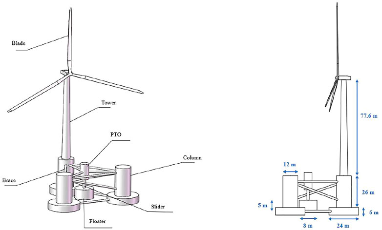
FIGURE 1. Integrated floating wind and wave integrated power generation platform.
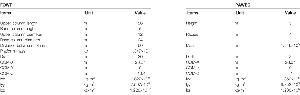
TABLE 1. Main parameters of the FOWT and PAWEC.
The hydrodynamic analysis of the FWWP is carried out using the AQWA software. The semi-submersible platform was simplified as three columns ignoring the effect of the tower and connecting components. The hydrodynamic model for the FWWP is shown in Figure 2, and five wave directions are considered in the frequency-domain analysis with the wave frequency ranging from 0.02 rad/s to 2.02 rad/s and step 0.05 rad/s.
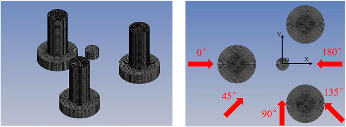
FIGURE 2. The hydrodynamic model for the FWWP.
Effects of Multi-Body Interaction
The heave radiation coefficients of the floater in the PAWEC were compared with those in the FWWP, as presented in Figure 3, while the difference in the platform heave radiation coefficient between the FOWT and FWWP was investigated, as shown in Figure 4. The hydrodynamic interaction has a great impact on the heave radiation coefficient of the floater. However, the hydrodynamic interaction has little effect on the heave radiation coefficient for the platform because the platform has a larger scale than the floater (Chen et al., 2020).
FIGURE 3. The comparison of heave radiation coefficients for the floater. (A) Added mass coefficient. (B) Wave damping coefficient.
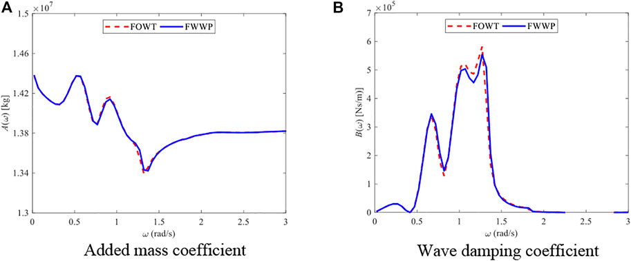
FIGURE 4. The comparison of heave radiation coefficients for the platform. (A) Added mass coefficient. (B) Wave damping coefficient.
The floater heave motion RAO of the PAWEC and the FWWP is compared considering different wave headings, as shown in Figure 5A. The floater response of the FWWP is more significant than that of the PAWEC under 0 , 135 , and 180 , which indicates that the FWWP plays a positive role in improving the performance of the wave energy converter under these wave directions. The platform heave RAO of the FWWP is the similar under different wave headings, as shown in Figure 5B. However, the RAO of the floater near the resonance frequency presents an excessive amplitude more than 3 m, which is obviously unreasonable for the existing draft design of the floater. One of the reasons is that AQWA cannot take into account fluid viscosity as it is based on potential flow theory, which requires viscosity correction of the oscillation floater. In addition, it will overpredict the wave surface rise around the multiple floating bodies, which will also increase the amplitude of floater motion. Therefore, the hydrodynamic viscosity correction of the calculation model is required.
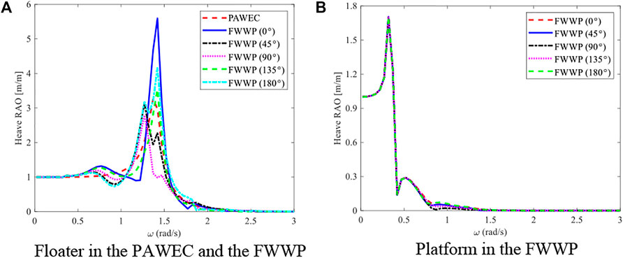
FIGURE 5. Heave motion RAO comparisons. (A) Floater in the PAWEC and the FWWP. (B) Platform in the FWWP.
Hydrodynamic Viscosity Correction
In this article, the CFD method is used to conduct the numerical test of free decay motion to obtain the viscosity coefficient by STAR CCM+. Because the platform motion response itself is small relatively, only the viscous effect of the floater is considered. In order to verify the accuracy of CFD calculation results, the numerical results are validated by the free decay model test which was carried out by TOM (2013), as shown in Figure 6. Meanwhile, the validated numerical technology is used to simulate the free decay test of the floater in STAR CCM+ software, as shown in Figure 7A. The computational domain was set as a 1/4 cylindrical three-dimensional pool. The bottom of the boundary conditions was the wall condition, the top and outer boundaries were the pressure outlet, and the side was the symmetric plane. The wave generated by the free decay movement of the floating body can impact the outer boundary and be reflected back. The damping length of the wave region of 1 m VOF is set at the outer boundary to eliminate the influence of the reflected wave on the free attenuation movement. The calculated viscous damping under three free decay simulations is shown in Table 2. The averaged value of the three simulations is selected as the viscous damping of the floater, which is introduced into AQWA in the form of an additional damping matrix.
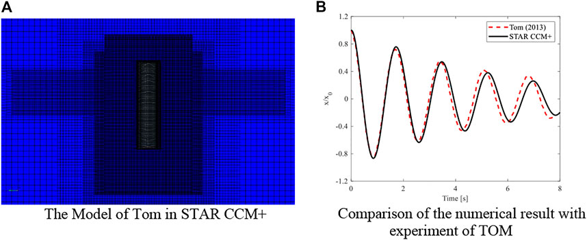
FIGURE 6. Verification of the CFD method with the model of TOM. (A) The model of TOM in STAR CCM+. (B) Comparison of the numerical result with the experiment of TOM.
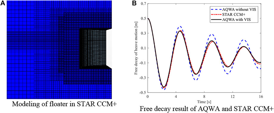
FIGURE 7. Investigation of viscous damping correction. (A) Modelling of the floater in STAR CCM+. (B) Free decay result of AQWA and STAR CCM+.
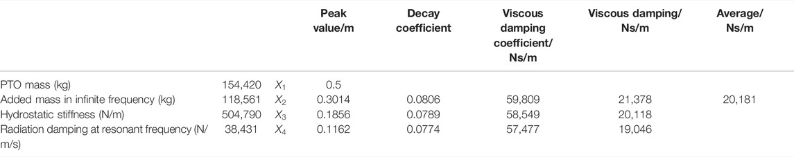
TABLE 2. Parameters related to viscous damping.
In order to verify the effect of viscous damping on the motion response of the floater, a free decay test with and without viscous damping has been carried out in AQWA and compared with the calculation results of STAR CCM+, as shown in Figure 7B. It can be seen that the free attenuation motion without correction is significantly greater than the STAR CCM+ result, while the motion response after viscous correction is similar with the results calculated by STAR CCM+, which indicates that the viscous damping of the floater is accurate and the viscous correction method is reasonable.
Due to the absence of viscous flow effects in the potential flow diffraction and radiation calculation, AQWA will also overpredict the rise of the wave surface around multiple floating bodies, resulting in inaccurate hydrodynamic calculation results, which will bring large errors to the time-domain analysis (Chen et al., 2021b; Zhu et al., 2021). In this study, an external lid as the artificial damping boundary condition is applied to the water surface around the multiple floating bodies (Ansys, 2016), as shown in Figure 8A. In this way, a more accurate prediction of the wave surface would be achieved. The wave elevation in the central area of the FWWP under different
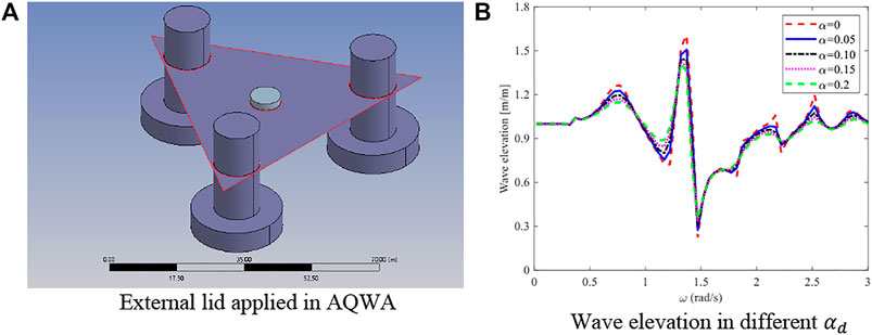
FIGURE 8. Correction of the artificial viscous damping in AQWA. (A) External lid applied in AQWA. (B) Wave elevation in different
Based on the viscosity correction (VIS) and the artificial viscous damping correction (EXT), the heave RAO motions of the floater for both the PAWEC and the FWWP under 0° wave heading are compared, as shown in Figure 9A. It can be seen that the RAO of the floater in the FWWP decreases significantly under the single VIS and EXT correction, respectively, while the response in the FWWP under the full correction condition is still larger than that in the PAWEC with VIS, indicating that the FWWP does improve the performance of the oscillating floater of the wave energy converter.
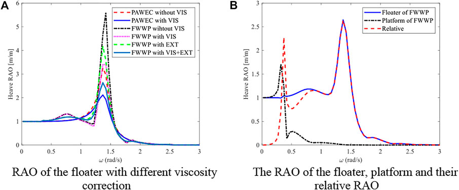
FIGURE 9. Heave RAO with hydrodynamic correction. (A) RAO of the floater with different viscosity corrections. (B) The RAO of the floater and platform and their relative RAO.
Since the wave power generation in the FWWP is calculated based on the relative motion between the floater and the platform, the relative RAO can be calculated according to Eq. 5, as shown in Figure 9B. Compared with the heave motion RAO of the floater in the FWWP, the first peak value appears at the low frequency of 0.37 rad/s due to the influence of the platform.
Coupling Dynamic Response Analysis
Modelling and Validation
The time-domain analysis of the FWWP under the wind and wave loading is carried out using AQWA. Two identical fender modules with opposite directions are set to simulate the PTO system, which is separately at the upper and lower ends of the floater connected to the platform. The mooring system of the platform and floater are realized by a nonlinear catenary cable and linear cable, respectively. The layout of the mooring line and the modelling of the FWWP in AQWA are shown in Figure 10. The mooring and PTO parameters are shown in Table 3. Since AQWA cannot directly consider the aerodynamic load, a user interaction file developed by Yang et al. (2020) is adopted for transferring the aerodynamic load calculated by the FAST open-source program to the numerical calculation of AQWA software. In this way, the fully coupled aero–hydro–PTO–mooring model is established and applied to the dynamic response analysis and power generation of the FWWP.
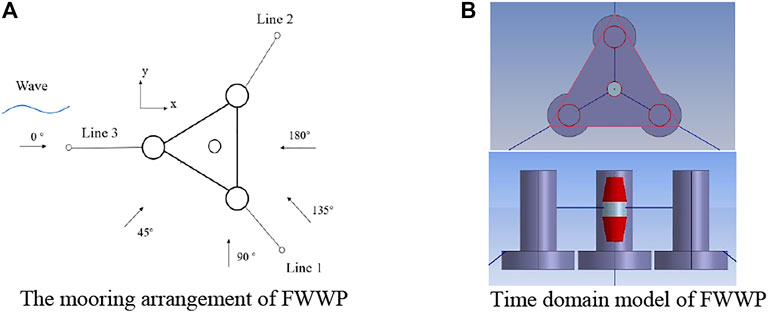
FIGURE 10. The hydrodynamic model of the FWWP. (A) The mooring arrangement of the FWWP. (B) Time-domain model of the FWWP.
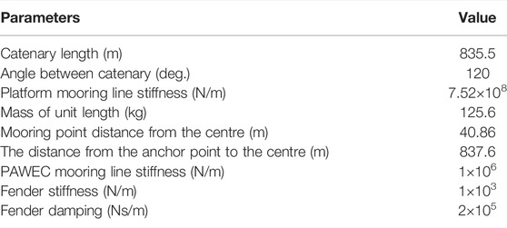
TABLE 3. Parameters for modelling in AQWA.
In order to verify the accuracy of the fully coupled numerical model of the FWWP based on the present method, the time-domain analysis has been conducted firstly for the single FOWT with a standard NERL 5 MW wind turbine under turbulent wind and irregular wave. The calculated surge, heave, and pitch motion response within 1000 s are then compared with the result in FAST under the same sea conditions, as shown in Figure 11. It can be seen that the motion trend of the two calculation results is similar. The observed discrepancies between FAST and AQWA are consistent with the comparisons by Yang et al. (2020), which may be due to the fact that the time-domain solvers for the platform dynamics in the two software adopt different integration methods.
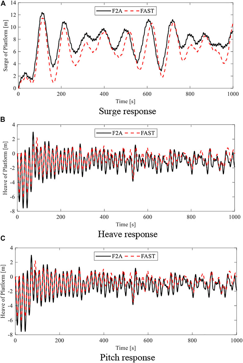
FIGURE 11. Verification of FAST and the present method. (A) Surge response. (B) Heave response. (C) Pitch response.
Time-Domain Analysis in Regular Waves
The time-domain analysis is carried out by the present method for investigating the performance of the FWWP in regular waves with an amplitude of 1 m, direction of 0°, and period of 8 s. The motion response of the platform in both the FWWP and FOWT are calculated under no wind and 11.4 m/s turbulent wind conditions, respectively. The surge, heave, and pitch motions of the platform in both the FWWP and FOWT are compared in Figures 12A–C. The surge and pitch motion of the platform in the FWWP are similar to those of the platform in the FOWT under the condition of no wind. When turbulent wind is applied, the surge and pitch motions of the platform in both the FWWP and FOWT increase significantly. However, the heave motion response of the platform in the FOWT is obviously larger than that in the FWWP. The main reason might lie in that the platform in the FWWP will be subjected to extra stiffness and damping under the coupling effect of the PTO system for heave motion response. In addition, comparing the calculated wind power for 11.4 m/s steady and turbulent wind, the instant and averaged wind power of two models agree well with each other, as shown in Figure 13, which implies that the wind power generation performance of the FWWP is not affected by the consideration of the wave energy converter.
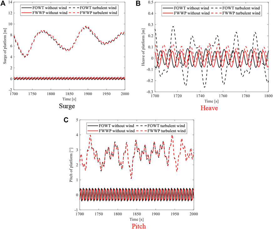
FIGURE 12. Platform motion in both the FOWT and FWWP. (A) Surge. (B) Heave. (C) Pitch.
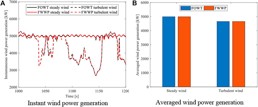
FIGURE 13. Wind power generation in the FOWT and FWWP. (A) Instant wind power generation. (B) Averaged wind power generation.
The natural frequency and period of the floater and platform are shown in Table 4. The performance of the PAWEC installed in the FWWP is investigated comparing with the single PAWEC. The wave power generation of both the single PAWEC and FWWP under the frequency domain (FD) and the time domain (TD) was calculated, respectively, while that of the FWWP with no wind and 11.4 m/s turbulent wind was also considered, as shown in Figure 14. The wave power generation of the FWWP is significantly larger than that of the PAWEC near the resonant period of 4.5 and 17.5 s for the floater and platform, respectively, while the generated power in the FWWP is similar to that of the PAWEC or even decreases in periods away from the resonant period. Particularly near the resonant periods, the wave power generation of the FWWP under turbulent wind is significantly improved compared with the power under the no-wind condition.
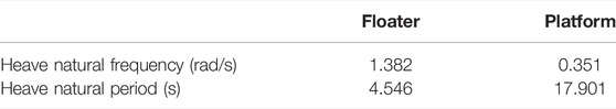
TABLE 4. Natural frequency of the floater and platform.
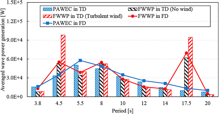
FIGURE 14. Wave power generation of the PAWEC and FWWP in the frequency and time domain.
In order to investigate the influence of the dynamic response on wave power generation of the FWWP, the heave motions of the floater and platform and their relative motion for the FWWP are compared to the floater heave motion of the PAWEC at four periods including 4.5, 8, 12, and 17.5 s, as exhibited in Figure 15. For the period of 4.5 s, the relative motion of the FWWP is close to the floater heave motion since the platform foundation heave motion is relatively small, which is much larger than the floater heave motion in the PAWEC. With the increase of period, the platform heave motion of the FWWP gradually increases while the phase is consistent with the floater. As a result, the relative motion of the FWWP is smaller than the response of the floater in the PAWEC. For the wave period of 17.5 s, the platform heave motion response increases significantly and its motion phase is nearly opposite to the floater heave motion, which makes the relative motion of the FWWP increase conspicuously and much higher than that of the floater heave motion of the PAWEC.
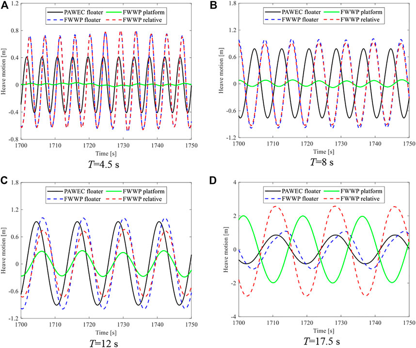
FIGURE 15. Heave motion of the floater in the PAWEC, compared with the floater and platform and their relative motion in the FWWP under regular wave. (A) T=4.5 s. (B) T=8 s. (C) T=12 s. (D) T=17.5 s.
Time-Domain Responses in Irregular Waves
The analysis of the FWWP in regular waves cannot realistically reflect its performance under real sea conditions. It is necessary to carry out the coupled dynamic response of the FWWP under irregular waves to obtain the actual motion response and power generation. The wind condition is the same as that of the regular wave, which is 11.4 m/s turbulent wind. Irregular wave history is transferred by the JONSWAP spectrum with a significant wave height of 3 m and wave direction of 0 deg. The heave response of the FWWP is analyzed and compared with that of the floater installed in the PAWEC under four periods including 4.5, 8, 12 and 17.5 s, as exhibited in Figure 16. The platform heave motion of the FWWP increases when the period increases, which is similar to its response under regular waves. The relative motion of the FWWP is obviously larger than that of the floater installed in the PAWEC at the peak period of both 4.5 and 8 s, while for the peak period of 12 s, the relative motion of the FWWP is smaller than that of the PAWEC floater due to the larger motion response of the platform with opposite phase. When the wave period is selected as 17.5 s, the platform motion response is much larger than that of the floater for the FWWP resulting in its much higher relative motion.
FIGURE 16. Heave motion of the floater in the PAWEC, compared with the floater and platform and their relative motion in the FWWP under irregular wave. (A) Tp=4.5 s. (B) Tp=8 s. (C) Tp=12 s. (D) Tp=17.5 s.
The averaged wave power generation of both the FWWP and the PAWEC for four periods is calculated with no wind and turbulent wind for the FWWP, as shown in Figure 17. The wave power generation of the FWWP is greater than that of the PAWEC for four periods, and it is improved significantly at 17.5 s. However, for the wave periods of 8, 12, and 17.5 s, the wave power generation of the FWWP under turbulent wind decreases compared with its the power generation without wind, indicating the wind load has a negative effect on the performance of the FWWP.

FIGURE 17. Averaged wave power generation for both the PAWEC and FWWP.
Furthermore, the heave power spectral density (PSD) of the FWWP is compared for four wave periods, as shown in Figure 18. The peak PSD of the platform is located at its natural frequency, which is less affected by incident wave frequency, while the heave PSD of the floater has peak values at both incident wave excitation frequency and natural frequency of the platform for the spectral peak periods of 4.5, 8 and 12 s. Therefore, the PSD of relative motion for the FWWP also has two peaks, which are smaller than the PSD of platform motion due to the existence of the floater. For the spectral peak period of 17.5 s, the wave excitation frequency is close to the natural frequency of the platform, which makes the heave motion PSD increase significantly.
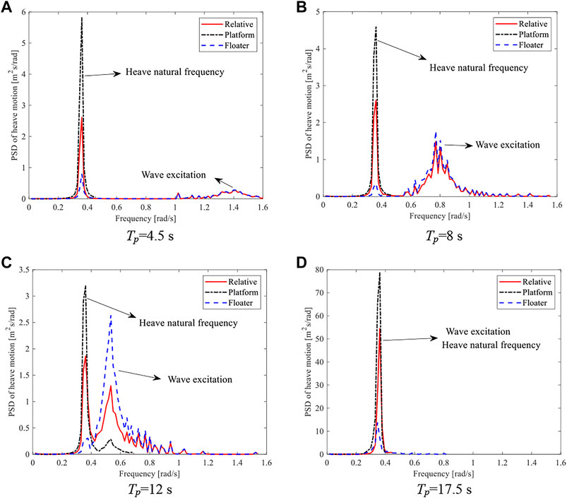
FIGURE 18. Power spectral density of the motion in the FWWP. (A) Tp=4.5 s. (B) Tp=8 s. (C) Tp=12 s. (D) Tp=17.5 s.
Conclusion
In this study, the coupled dynamic responses of the proposed FWWP are analysed by using the conventional hydrodynamic software AQWA together with the F2A method. First, the hydrodynamics of three models including the single PAWEC, single FOWT, and FWWP are compared to investigate the effects of hydrodynamic interactions of the FWWP on the wave power generation and the system dynamics. Additional heaving viscous damping of the PAWEC is considered to produce more realistic predictions of its heaving motions, which is determined from the free heaving decay test using the CFD simulation software Star CCM+. In addition, the external damping lid is incorporated in the frequency-domain hydrodynamic analyses of the FWWP to reduce the unrealistically excessive wave elevation caused by the resonance between the platform and floater of the FWWP. Then, a fully coupled model for the FWWP is established by calling OpenFAST in AQWA using the F2A method. The coupled model is then validated with OpenFAST for analysing the dynamics of the single FOWT. Finally, the coupled motion responses and wind and wave power generation of the FWWP are compared with those of the single PAWEC and FOWT for both the regular and irregular waves. Some concluding remarks can be drawn as follows:
(1) The hydrodynamic interaction of the FWWP is found to have significant influences on the hydrodynamics of the PAWEC. The heave RAO response of the PAWEC in the FWWP is much larger than that of the single PAWEC for most incident wave directions, which is particularly significant for the wave incident angle of 0°. However, the hydrodynamics of the platform in the FWWP is barely affected since the size of the floater is much smaller compared with that of the platform.
(2) The viscosity correction method adopted in this study may help to mitigate the shortcoming that AQWA cannot consider fluid viscosity and may generate overestimated results. In addition, the fully coupled aero–hydro–PTO–mooring numerical model of FWWP established by the F2A method is verified with OpenFAST and good agreement is achieved, which provides a feasible method to investigate the coupled dynamic responses and power generation of the FWWP.
(3) Based on the time-domain analyses in both regular and irregular waves, it can be summarized that the performance of the PAWEC of the FWWP is found to be generally improved. The wave power generations near the resonant frequencies of the floater and platform are found to be greatly enhanced. The wind load is found to have a significant influence on the wave power generation of the FWWP, which implies that a fully coupled model is needed for the optimization of WECs for the FWWP. In addition, the existence of the PAWEC generally has no effect on the wind power generation of the FWWP, but it may help to reduce the heave motion of the platform of the FWWP to some extent due to the coupling effects of the PTO system between the PAWEC and FOWT.
It needs to be noted that the PTO parameters are not optimized in this study, which makes the wave power generation much smaller than the generated wind power. Further studies are recommended to provide a systematic analysis on the PTO parameters. In addition, the performance of multiple WECs integrated with one FOWT may also be of great interest.
Data Availability Statement
The original contributions presented in the study are included in the article/Supplementary Material; further inquiries can be directed to the corresponding author.
Author Contributions
MC: methodology, supervision, validation, formal analysis, writing—review and editing, and funding acquisition. PX: methodology, software, investigation, data curation, writing—original draft, and visualization. HZ: software, investigation, and data curation. CL: writing—review and editing. XZ: supervision and validation.
Funding
The authors gratefully acknowledge the financial support from the National Natural Science Foundation of China (Grant No. 52171275) and the Natural Science Foundation of Hainan Province, PR China (Grant No. 520MS072).
Conflict of Interest
Author XZ was employed by Poly Changda Engineering Co. Ltd.
The remaining authors declare that the research was conducted in the absence of any commercial or financial relationships that could be construed as a potential conflict of interest.
Publisher’s Note
All claims expressed in this article are solely those of the authors and do not necessarily represent those of their affiliated organizations, or those of the publisher, the editors, and the reviewers. Any product that may be evaluated in this article, or claim that may be made by its manufacturer, is not guaranteed or endorsed by the publisher.
References
Aubault, A., Alves, M., Sarmento, A., Roddier, D., and Peiffer, A. (2011). Modeling of an Oscillating Water Column on the Floating Foundation WindFloat. Proceedings of the International Conference on Offshore Mechanics and Arctic Engineering. January 2011, Hamburg, Germany. doi:10.1115/omae2011-49014
Chen, M., Eatock Taylor, R., and Choo, Y. S. (2017). Investigation of the Complex Dynamics of Float-Over Deck Installation Based on a Coupled Heave-Roll-Pitch Impact Model. Ocean. Eng. 137, 262–275. doi:10.1016/j.oceaneng.2017.04.007
Chen, M., Wang, R., Xiao, P., Zhu, L., Li, F., and Sun, L. (2020). Numerical Analysis of a Floating Semi-submersible Wind Turbine Integrated with a Point Absorber Wave Energy Convertor. Proceedings of the 30th International Ocean and Polar Engineering Conference. October 2020, Shanghai, China.
Chen, M., Guo, H., Wang, R., Tao, R., and Cheng, N. (2021a). Effects of Gap Resonance on the Hydrodynamics and Dynamics of a Multi-Module Floating System with Narrow Gaps. J. Mar. Sci. Eng. 9 (11), 1256. doi:10.3390/jmse9111256
Chen, M., Xiao, P., Zhang, Z., Sun, L., and Li, F. (2021b). Effects of the End-Stop Mechanism on the Nonlinear Dynamics and Power Generation of a Point Absorber in Regular Waves. Ocean. Eng. 242, 110123. doi:10.1016/j.oceaneng.2021.110123
Cummins, W. (1962). The impulse response function and ship motions. Schiffstechnik 9 (1661), 101–109.
Folley, M. (2016). Numerical Modelling of Wave Energy Converters: State-Of-The-Art Techniques for Single Devices and Arrays. Cambridge, Massachusetts. Academic Press
Gaspar, J. F., Kamarlouei, M., Thiebaut, F., and Guedes Soares, C. (2021). Compensation of a Hybrid Platform Dynamics Using Wave Energy Converters in Different Sea State Conditions. Renew. Energy 177, 871–883. doi:10.1016/j.renene.2021.05.096
Izquierdo-Pérez, J., Brentan, B. M., Izquierdo, J., Clausen, N.-E., Pegalajar-Jurado, A., and Ebsen, N. (2020). Layout Optimization Process to Minimize the Cost of Energy of an Offshore Floating Hybrid Wind-Wave Farm. Processes 8 (2), 139. doi:10.3390/pr8020139
Jonkman, J. M., and Buhl, M. L. (2005). FAST User's Guide, 365. Denver W Pkwy, Golden, CO, USA. USA: National Renewable Energy Laboratory Golden, CO.
Jonkman, J. M., Hayman, G., Jonkman, B., and Damiani, R.Draft Report (2015). AeroDyn V15 User’s Guide and Theory Manual. Denver W Pkwy, Golden, CO, USA. USA: National Renewable Energy Laboratory Golden, CO
Karimirad, M., and Koushan, K. (2016). WindWEC: Combining Wind and Wave Energy Inspired by Hywind and Wavestar. Proceedings of the IEEE International Conference on Renewable Energy Research and Applications (ICRERA). November 2016, Birmingham, UK. doi:10.1109/ICRERA.2016.7884433
Lee, H., Poguluri, S., and Bae, Y. (2018). Performance Analysis of Multiple Wave Energy Converters Placed on a Floating Platform in the Frequency Domain. Energies 11 (2), 406. doi:10.3390/en11020406
Li, J., Shi, W., Zhang, L., Michailides, C., and Li, X. (2021). Wind-Wave Coupling Effect on the Dynamic Response of a Combined Wind-Wave Energy Converter. J. Mar. Sci. Eng. 9 (10), 1101. doi:10.3390/jmse9101101
Luan, C., Michailides, C., Gao, Z., and Moan, T. (2014).Modeling and Analysis of a 5 MW Semi-submersible Wind Turbine Combined with Three Flap-type Wave Energy Converters. Proceedings of the International Conference on Offshore Mechanics and Arctic Engineering. October 2014, New York, NY, USA. doi:10.1115/omae2014-24215
McTiernan, K. L., and Sharman, K. T. (2020). Review of Hybrid Offshore Wind and Wave Energy Systems. J. Phys. Conf. Ser. 1452, 012016. doi:10.1088/1742-6596/1452/1/012016
Muliawan, M. J., Karimirad, M., Moan, T., and Gao, Z. (2012). STC (Spar-Torus Combination): a Combined Spar-type Floating Wind Turbine and Large Point Absorber Floating Wave Energy Converter—Promising and Challenging Proceedings of the International Conference on Offshore Mechanics and Arctic Engineering. July 2012, Rio de Janeiro, Brazil.
Peiffer, A., Roddier, D., and Aubault, A. (2011). Design of a Point Absorber inside the WindFloat Structure. Proceedings of the International Conference on Offshore Mechanics and Arctic Engineering. October 2011, Estoril, Portugal. doi:10.1115/omae2011-49015
Pérez-Collazo, C., Greaves, D., and Iglesias, G. (2015). A Review of Combined Wave and Offshore Wind Energy. Renew. Sustain. Energy Rev. 42, 141–153. doi:10.1016/j.rser.2014.09.032
Ren, N., Ma, Z., Shan, B., Ning, D., and Ou, J. (2020). Experimental and Numerical Study of Dynamic Responses of a New Combined TLP Type Floating Wind Turbine and a Wave Energy Converter under Operational Conditions. Renew Energy 151, 966–974. doi:10.1016/j.renene.2019.11.095
Ruehl, K., Michelen, C., Kanner, S., Lawson, M., and Yu, Y. H. (2014). Preliminary Verification and Validation of WEC-Sim, an Open-Source Wave Energy Converter Design Tool. Int. Conf. offshore Mech. Arct. Eng. 45547, 312. doi:10.1115/omae2014-24312
Si, Y., Chen, Z., Zeng, W., Sun, J., Zhang, D., Ma, X., et al. (2021). The Influence of Power-Take-Off Control on the Dynamic Response and Power Output of Combined Semi-submersible Floating Wind Turbine and Point-Absorber Wave Energy Converters. Ocean. Eng. 227, 108835. doi:10.1016/j.oceaneng.2021.108835
Sun, K., Xie, G., and Zhou, B. (2021). Type Selection and Hydrodynamic Performance Analysis of Wave Energy Converters. J. Harbin Eng. Univ. 42 (1), 8–14.
Tom, N. M. (2013). Design and Control of a Floating Wave-Energy Converter Utilizing a Permanent Magnet Linear Generator. Berkeley, California. Berkeley: University of California
Walker, D. A. G., Eatock Taylor, R., Taylor, P. H., and Zang, J. (2008). Wave Diffraction and Near-Trapping by a Multi-Column Gravity-Based Structure. Ocean. Eng. 35 (2), 201–229. doi:10.1016/j.oceaneng.2007.08.005
Wu, X., Hu, Y., Li, Y., Yang, J., Duan, L., Wang, T., et al. (2019). Foundations of Offshore Wind Turbines: A Review. Renew. Sustain. Energy Rev. 104, 379–393. doi:10.1016/j.rser.2019.01.012
Yang, Y., Bashir, M., Wang, J., Yu, J., and Li, C. (2020). Performance Evaluation of an Integrated Floating Energy System Based on Coupled Analysis. Energy Convers. Manag. 223, 113308. doi:10.1016/j.enconman.2020.113308
Zhang, Y., Zhao, Y., Sun, W., and Li, J. (2021). Ocean Wave Energy Converters: Technical Principle, Device Realization, and Performance Evaluation. Renew. Sustain. Energy Rev. 141, 110764. doi:10.1016/j.rser.2021.110764
Zhu, H., Hu, C., Sueyoshi, M., and Yoshida, S. (2020). Integration of a Semisubmersible Floating Wind Turbine and Wave Energy Converters: an Experimental Study on Motion Reduction. J. Mar. Sci. Technol. 25 (3), 667–674. doi:10.1007/s00773-019-00671-y
Keywords: floating offshore wind turbine (FOWT), point absorber WEC, integrated wind-wave power generation, fully coupled analysis, wave power generation
Citation: Chen M, Xiao P, Zhou H, Li CB and Zhang X (2022) Fully Coupled Analysis of an Integrated Floating Wind-Wave Power Generation Platform in Operational Sea-States. Front. Energy Res. 10:931057. doi: 10.3389/fenrg.2022.931057
Received: 28 April 2022; Accepted: 17 May 2022;
Published: 28 June 2022.
Edited by:
Zhengshun Cheng, Shanghai Jiao Tong University, ChinaReviewed by:
Nianxin Ren, Hainan University, ChinaXiaoxian Guo, Shanghai Jiao Tong University, China
Copyright © 2022 Chen, Xiao, Zhou, Li and Zhang. This is an open-access article distributed under the terms of the Creative Commons Attribution License (CC BY). The use, distribution or reproduction in other forums is permitted, provided the original author(s) and the copyright owner(s) are credited and that the original publication in this journal is cited, in accordance with accepted academic practice. No use, distribution or reproduction is permitted which does not comply with these terms.
*Correspondence: Chun Bao Li, bGVlY3ViYW9Ad2h1dC5lZHUuY24=