 Eun Joo Park
 Siddharth Komini Babu
- MPA-11: Materials Synthesis and Integrated Devices, Los Alamos National Laboratory, Los Alamos, NM, United States
The membrane-based electrolysis of water is a growing topic of interest due to the advantages of employing membranes in hydrogen production efficiency and system safety over the traditional alkaline water electrolysis. Ion-exchange membranes with low gas permeability are highly desirable for stable and safe operation of membrane-based water-splitting technologies, hence gas permeability through ion-exchange membranes needs to be properly assessed with standardized methods. We addressed three methods to measure gas permeability of ion-exchange membranes, a pressure permeation cell, chronoamperometry microelectrodes, and in situ testing of the membrane electrode assembly, and provide a guideline for choosing the appropriate method for the targeted operating conditions of the water electrolyzers.
Introduction
Electrochemical splitting of water to generate green hydrogen as an energy carrier is a promising method for sustainable fuel production. Compared to the traditional alkaline electrolyzer that uses aqueous alkaline electrolytes confined in a porous diaphragm, solid electrolyte water electrolyzers use ion-conducting membranes serving both as electrolytes and as a gas separator. This zero-gap design using non-porous membranes has distinct advantages in terms of efficiency, safety, and durability: low internal resistance, high hydrogen production rate, high-pressure operation, and the ability to prevent intermixing of the gaseous products.
The proton exchange membrane (PEM) water electrolyzer splits water at the anode into oxygen and protons, then the proton migrates through the PEM to the cathode where hydrogen is evolved. On the other hand, the anion exchange membrane (AEM) water electrolyzer splits water at the cathode into hydrogen and hydroxide ions, and the latter migrates through the AEM, liberating oxygen at the anode. Both membrane-based water electrolyzer systems allow the operation of the cell under differential pressure to produce high-pressure hydrogen and atmospheric pressure oxygen to minimize the need for additional mechanical compression for hydrogen use or storage (Motz et al., 2021). Preventing physical crossover of the gaseous products of electrolysis is of particular interest due to the flammable nature of hydrogen and possible formation of an explosive mixture of hydrogen and oxygen (Grigoriev et al., 2009; Xiang et al., 2016). In addition, interdiffusion of reactant gases may cause the formation of aggressive radical species such as peroxide, leading the chemical degradation of the ion-exchange membranes, especially perfluorosulfonic acid-based PEMs. Therefore, a proper measurement of the gas permeation rate across the membrane is necessary in the context of efficiency, safety, and durability of water electrolyzer systems.
In this protocol, three methods used for the measurement of gas permeability through an ion-exchange membrane are summarized and described in a procedure to help to establish a guideline for the ion-exchange membrane–based water-splitting technology community.
Protocol Scope
Scope and Applicability
- This protocol is designated to develop standard procedures for the measurement of gas permeability of an ion-exchange membrane, including PEM and AEM. Hydrogen and oxygen would be the gases of the interest for the purpose.
Summary of Method
- The gas permeation rate can be measured using (A) a pressure permeation cell, (B) chronoamperometry with microelectrodes, or (C) in situ testing of the membrane electrode assembly (MEA). A pressure permeation cell is used with controlled humidified gas flow and gas chromatography (GC) or mass spectrometry. For the chronoamperometric technique, a microelectrode is used for hydrogen permeability, and the oxygen permeability can be calculated from the voltammetric limiting currents. In situ testing uses MEA configurations for fuel cell testing for hydrogen or oxygen permeability measurement, quantifying the limiting current of the electrochemical reaction through the membrane.
Personnel Qualifications/Responsibilities
- The user should be properly trained in hydrogen safety and pressure safety prior to the permeability measurement. The user should be properly trained to safely operate the instruments and able to perform the analysis to collect data used for permeability coefficient calculation.
Health and Safety Warning
- The user should be wearing appropriate personal protective equipment, including protective eyewear, gloves, and laboratory coats, in the laboratory at the time when the measurement procedure is followed. The use of compressed gases in laboratory settings need to be permitted prior to protocol implementation.
Equipment and Supplies
The following equipment and supplies are needed for each measurement:
A) Pressure Permeation Cell
- For the measurement at low pressure, a conventional diffusion cell could be used. For high-pressure testing, an electrolyzer cell rated to a pressure greater than the highest pressure is required for the measurement, that is, EH-50 from Greenlight (rated to 50 bar).
- A porous transport layer (PTL) and gas diffusion layer (GDL) will play an important role in H2 permeation as they will affect the compression of the membrane. Use a Ti sinter or Ti felt for the anode PTL, that is, 2GDL10-0.25 Bekaert, and Ti PTL or carbon GDL for the cathode GDL, that is, MGL370, AvCarb.
- A measure of 1–2 mil (1 mil = 0.001 inches or 25.4 μm) of PTFE for the sub-gasket.
- An instrument to monitor the gas product, that is, gas chromatography (GC).
B) Microelectrode Chronoamperometry
- Pt microdisk working electrode.
- Pt counter electrode and Pt dynamic hydrogen electrode.
- A controlled humidity chamber for control over gas, pressure, humidity, and temperature.
- A potentiostat, that is, EG&G PAR Model 283.
- Syringe filters (PTFE, 0.2 or 0.45 μm).
- A measure of 0.1 M of H2SO4 or 0.1 M of NaOH aqueous solution.
C) In Situ Measurement in MEA
- A standard single-cell hardware (one example is shown in Figure 1).
- GDL.
- A fuel cell station, that is, Scribner 850e.
- An electrochemical interface potentiostat, that is, Solartron 1287.
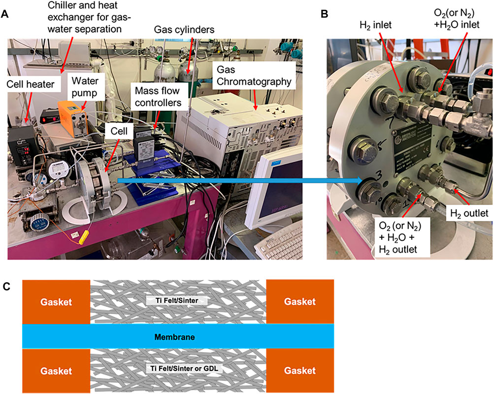
FIGURE 1. (A) Experiment set up for ex situ gas permeation measurement using a pressure permeation cell, (B) closed-up view of the cell with gas inlet and outlets, and (C) cell assembly diagram.
Procedure
Step-By-Step Procedure
A) Pressure Permeation Cell (Broka and Ekdunge, 1997; Bernt et al., 2020)
1. Prepare a flat, dry membrane piece with a known thickness (wet) and a matching hardware plate (greater than the active area, e.g., 100 cm2 plate for 50 cm2 active area) to provide a good seal for the hardware. Any wrinkles in the membrane may lead to gas leak and hardware not being able to achieve the desired pressures.
2. Assemble an electrolyzer cell–like standard operation with the exception of no catalyst layer on electrodes and utilizing a PTL without Pt coating (Figure 1), where each plate is connected to a gas inlet and outlet. Adding a sub-gasket between the PTL and the membrane is recommended to avoid PTL edges causing pinholes in the membrane. For instance, for the PTL area of 50 cm2; the sub-gasket masks the active area up to 49 cm2.
3. Before starting the experiment, check the pressure to ensure proper sealing of the hardware at high pressure. Flow N2 on both the anode and cathode side at a fixed flow rate (<300 sccm) through a mass flow controller similar to the actual experiment. Gradually increase the pressure on the cathode side to the highest operating pressure while the anode side is at 1 atm. If the anode side is not able to reach the highest pressure, then repeat the cell assembly with a new membrane. For low-pressure testing, the cathode pressure should be 5 atm, and for high pressure, the cathode pressure should be 30 atm.
4. After the pressure check, flow H2 to the cathode side and a carrier gas to the anode side at a fixed flow rate (<300 sccm). Flow water at 2 ml min−1 cm−2 through a pump on the anode side to provide sufficient hydration to the membrane. The carrier gas can be either N2 or O2 depending on the membrane; if the membrane contains gas recombination catalyst, the carrier gas should be O2 otherwise N2 could be used. Set partial pressure of the H2 and carrier gas at 1 atm accounting for the saturation pressure of water at the operating temperature (50–80°C).
5. The exhaust of the anode should be connected to a gas–water separator or chiller to remove the water from the gas.
6. If O2 is used as carrier gas, an inert gas (N2) should be introduced at a known flow rate after the anode exhaust and before the gas–water separator. When the carrier gas is O2, gas dilution with N2 is added, to prevent the exhaust gas from the gas–water separator from reaching flammable concentration levels of H2. For safety, it is advised to maintain the H2 concentration in the exhaust stream to less than 1% using dilution. This step is not required if N2 is used as a carrier gas.
7. The gaseous exhaust from the gas–water separator could be connected directly to the analyzer (GC).
8. After the desired pressure is set on the anode and cathode, let the cell stabilize for about 30 min before taking measurement in GC. Repeat the measurement until a stable concentration reading is reached, that is, at least five measurements.
9. Take measurements of the H2 concentration in the carrier gas at different partial pressures of H2 up to the operating conditions or system limitation.
10. If N2 dilution is utilized, ensure to correct the H2 concentration for the dilution with the N2 flow rate used.
B) Chronoamperometric Technique Using Microelectrodes (Beattie et al., 1999; Gode et al., 2002; Astill et al., 2009; Chlistunoff, 2014; Yim et al., 2015)
1. Dissolve an ion-exchange membrane in a solvent to prepare a 5 wt% ionomer solution. Filter through the solution with a syringe filter (PTFE, 0.2 or 0.45 μm) to remove any dust particle.
2. Drop-cast a thin layer of the solution on the Pt microdisk electrode.
3. Connect the microelectrode to the other sides of the glass body of the electrode by an ion conductive ribbon, for example, Nafion™ for PEM or quaternized Diels–Alder polyphenylene (Hibbs, 2013) for AEM, which acts as an electrolytic bridge between the external reference and working electrode (Figure 2A).
4. Connect the microelectrode to the hydrogen reference electrode (6% H2 in Ar ∣ Pt ∣ 0.1 M H2SO4 or NaOH) and place it in a controlled humidity chamber.
5. Before the experiments, cycle the electrode potential at 50 mV s−1 between 0 and +1.4 V using a potentiostat until a stable voltammogram is obtained. In order to provide a consistent electrode pretreatment and a clean Pt surface for every experiment, keep the microelectrode for 10 s at 1.4 V before applying a cathodic potential step or voltammetric scan.
6. Hold the potential of the microelectrode at 1.2 V for 20 s, and then proceed to 0.4 V where O2 reduction is diffusion controlled for 5 s.
C) In Situ Measurement in MEA (Kocha et al., 2006)
1. Prepare a flat, dry membrane piece with a known thickness (wet) and a matching hardware plate.
2. Assemble a standard fuel cell MEA with GDLs. Flow humidified H2 (4% in N2) on the anode side of the electrochemical cell, which acts as the reference and counter electrode. Flow humidified nitrogen to the cathode at 300 sccm (Figure 3A).
3. Apply voltage with a potentiostat and measure the resulting currents from 0 to 0.6 V with 1 mV s−1 scan rate. H2 that crosses over to the other side of the membrane gets oxidized at the cathode by the application of a voltage.
4. Obtain the H2 oxidation current density generated from the voltammogram by the y-axis intercept of a linear fit between 0.25 and 0.35 V (Figure 3B).
5. For oxygen permeability measurement (Baik et al., 2013; Zhang et al., 2013), flow humidified O2 to the anode instead of H2 in N2. Apply voltage with a potentiostat and measure the resulting currents from 0.4 to 1.1 V in increments of 0.1 V. Obtain the O2 crossover limiting current between 0.8 and 1.1 V.
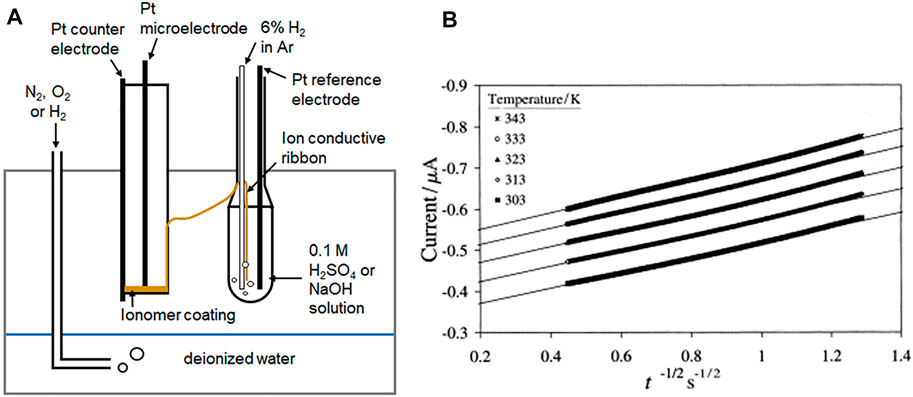
FIGURE 2. (A) Representative microelectrode set up and (B) example of I versus t−1/2 plots for O2 reduction at a Pt ∣ BAM® 407 membrane interface (Beattie et al., 1999. Copyright 1999 Elsevier Science S.A.).
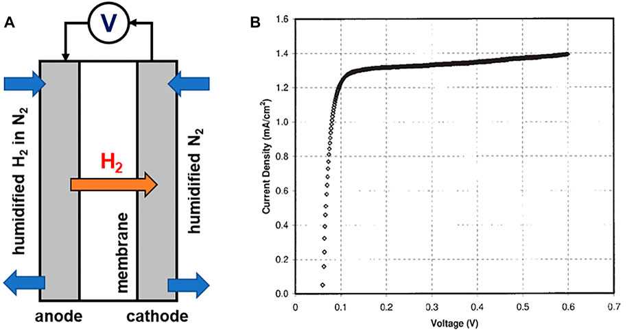
FIGURE 3. Representative experimental set up for (A) in situ MEA measurement for hydrogen permeation and (B) example of linear sweep voltammogram to measure the hydrogen crossover current density (Kocha et al., 2006. Copyright 1999–2022 John Wiley & Sons, Inc.).
Data Collection and Analysis
All raw experimental data should be recorded in a laboratory notebook with the date of measurement. Any observation during the measurement and analysis should be also noted for future references.
A) Pressure Permeation Cell
Calculate the corresponding permeation rate of hydrogen, p (mol cm−1 s−1), using the following equation:
where 22.4 is the conversion factor (1 mol = 22.4 L at standard temperature and pressure), xH2 is the hydrogen concentration in the carrier gas (mol L−1), Q is the flow rate of the carrier gas (sccm, kmol s−1), δ is the membrane thickness (wet, cm), and A is the permeating area of the MEA (cm2).
B) Chronoamperometric Technique
Chronoamperometric determination of diffusion coefficient (D b, cm2 s−1) and solubility (C b, mol cm−3) of hydrogen or oxygen in the membrane can be determined from the linear regression analysis of the experimental slope and intercept (int) of I vs. t −1/2 plots (Figure 2B).
where r is the radius of the microdisc electrode (cm), n is the number of electrons, F is the Faraday constant (96,485 s A mol−1), and n is the number of electrons (mol).
D b and C b are used to calculate gas permeability (p=D b C b , mol cm−1 s−1) of the membrane.
C) In Situ Measurement in MEA
The hydrogen permeation rate, p (mol cm−1 s−1), of the membrane can be expressed as:
where i H2 is the crossover current density of hydrogen (A cm−2), p H2 is the feed partial pressure of hydrogen (mol−1), th is the wet thickness the membrane (cm), F is the Faraday constant (96,485 s A mol−1), and n is the number of electrons (mol).
Quality Control and Quality Assurance
Instrument or Method Calibration and Standardization
- It is recommended to start the measurement with the commercially available membranes with the reported hydrogen and oxygen permeation rate in the literature (Nafion 112, Nafion 117 (Sakai et al., 1985; Beattie et al., 1999; Kim and Lee, 2015) or commercially available AEMs (Henkensmeier et al., 2021)) as a reference point.
- The GC for the pressure permeation cell needs to be properly calibrated with the gas standards prior to the analysis.
Cautions
- Special cautions needed during the measurement include avoiding inhalation of vapor or mist, ensuring adequate ventilation of the space, and removing all sources of ignition, heat, open flames, and sparks. No smoking or electrostatic charge is allowed. An oxygen cylinder has to be separated from hydrogen or combustible materials. All gas cylinders must be kept tightly closed in a dry, well-ventilated place.
- When using a membrane with gas recombination layers and O2 is used as a carrier gas, it is necessary to monitor the H2 content in O2 with a combustible gas detection system.
Interferences
- The pressure effect on the gas permeation rate is significant to the measurement. The gas permeation rates measured under pressurized conditions, such as pressure cells and microelectrodes with pressurized gases, are higher than those measured by non-pressurized techniques. For the systems operating under pressurized conditions, it is appropriate to measure the gas permeation rate under a similar pressure condition. Other non-pressurized methods such as diffusion cells and microelectrodes without pressurized gases can be used for general screening or comparing the gas permeation rate of different ion-exchange membranes.
- Gas permeability strongly depends on the hydration level of membranes. The membrane needs to be in the fully hydrated state for the measurement, and insufficient hydration to the membrane can result in a low permeation measurement.
- Gas permeability as membrane properties is measured in pure water. In a practical system, AEM water electrolyzers often circulate alkaline solution, for example, NaOH, KOH, or K2CO3 solution (0.1–2 M) (Kraglund et al., 2016), and a high concentration of the solution may significantly impact the gas permeability by lowering diffusivity.
Discussion
This protocol describes three methods that can be used to measure gas permeability across membranes of interest. All three methods can be applied to measure hydrogen permeability. Oxygen permeability can be measured by either microelectrodes or in situ measurement in MEA, yet, it is of less concern than hydrogen crossover due its production at ambient pressure and the lower permeation rate of oxygen than that of hydrogen (Sakai et al., 1985).
For a membrane used in high differential pressure operations or a membrane with recombination layers, a pressure permeation cell would be suitable. Microelectrode chronoamperometry would be favored when the membrane is available in an ionomer solution. Using MEA configuration would be preferred when hardware for the fuel cell testing set up is available. Running different methods on the same membrane sample would result in similar gas permeabilities (Kim and Lee, 2015). It is recommended to identify the operating conditions of water electrolyzers to select the appropriate gas permeation measurement methods for the membranes.
Data Availability Statement
The original contributions presented in the study are included in the article; further inquiries can be directed to the corresponding author.
Author Contributions
EP and YK wrote the first draft of the manuscript. SK provided the setup and procedure for pressure permeation measurement. EP revised the manuscript with help from SK and YK.
Conflict of Interest
The authors declare that the research was conducted in the absence of any commercial or financial relationships that could be construed as a potential conflict of interest.
Publisher’s Note
All claims expressed in this article are solely those of the authors and do not necessarily represent those of their affiliated organizations, or those of the publisher, the editors, and the reviewers. Any product that may be evaluated in this article, or claim that may be made by its manufacturer, is not guaranteed or endorsed by the publisher.
Acknowledgments
We thank Kathy Ayers and Diana De Porcellinis for providing helpful comments. The authors gratefully acknowledge research support from the HydroGEN Advanced Water Splitting Materials Consortium, established as part of the Energy Materials Network under the U.S. Department of Energy, Office of Energy Efficiency and Renewable Energy, Fuel Cell Technologies Office (Program Manager: D. Peterson). Los Alamos National Laboratory is operated by Triad National Security, LLC under U.S. Department of Energy under contract no. 89233218CNA000001.
References
Astill, T., Xie, Z., Shi, Z., Navessin, T., and Holdcroft, S. (2009). Factors Influencing Electrochemical Properties and Performance of Hydrocarbon-Based Electrolyte PEMFC Catalyst Layers. J. Electrochem. Soc. 156 (4), B499. doi:10.1149/1.3082119
Baik, K. D., Hong, B. K., and Kim, M. S. (2013). Novel Technique for Measuring Oxygen Crossover through the Membrane in Polymer Electrolyte Membrane Fuel Cells. Int. J. hydrogen energy 38 (21), 8927–8933. doi:10.1016/j.ijhydene.2013.04.142
Beattie, P. D., Basura, V. I., and Holdcroft, S. (1999). Temperature and Pressure Dependence of O2 Reduction at Pt|Nafion 117 and Pt|BAM 407 Interfaces. J. Electroanal. Chem. 468 (2), 180–192. doi:10.1016/s0022-0728(99)00164-3
Bernt, M., Schröter, J., Möckl, M., and Gasteiger, H. A. (2020). Analysis of Gas Permeation Phenomena in a PEM Water Electrolyzer Operated at High Pressure and High Current Density. J. Electrochem. Soc. 167 (12), 124502. doi:10.1149/1945-7111/abaa68
Broka, K., and Ekdunge, P. (1997). Oxygen and Hydrogen Permeation Properties and Water Uptake of Nafion® 117 Membrane and Recast Film for PEM Fuel Cell. J. Appl. Electrochem. 27 (2), 117–123. doi:10.1023/a:1018469520562
Chlistunoff, J. (2014). Oxygen Permeability of Cast Ionomer Films from Chronoamperometry on Microelectrodes. J. Power Sources 245, 203–207. doi:10.1016/j.jpowsour.2013.06.128
Gode, P., Lindbergh, G., and Sundholm, G. (2002). In-situ Measurements of Gas Permeability in Fuel Cell Membranes Using a Cylindrical Microelectrode. J. Electroanal. Chem. 518 (2), 115–122. doi:10.1016/s0022-0728(01)00698-2
Grigoriev, S. A., Millet, P., Korobtsev, S. V., Porembskiy, V. I., Pepic, M., Etievant, C., et al. (2009). Hydrogen Safety Aspects Related to High-Pressure Polymer Electrolyte Membrane Water Electrolysis. Int. J. Hydrogen Energy 34 (14), 5986–5991. doi:10.1016/j.ijhydene.2009.01.047
Henkensmeier, D., Najibah, M., Harms, C., Žitka, J., Hnát, J., and Bouzek, K. (2021). Overview: State-Of-The Art Commercial Membranes for Anion Exchange Membrane Water Electrolysis. J. Electrochem. Energy Convers. Storage 18 (2). doi:10.1115/1.4047963
Hibbs, M. R. (2013). Alkaline Stability of Poly(phenylene)-Based Anion Exchange Membranes with Various Cations. J. Polym. Sci. Part B Polym. Phys. 51 (24), 1736–1742. doi:10.1002/polb.23149
Kim, Y. S., and Lee, K.-S. (2015). Fuel Cell Membrane Characterizations. Polym. Rev. 55 (2), 330–370. doi:10.1080/15583724.2015.1011275
Kocha, S. S., Deliang Yang, J., and Yi, J. S. (2006). Characterization of Gas Crossover and its Implications in PEM Fuel Cells. AIChE J. 52 (5), 1916–1925. doi:10.1002/aic.10780
Kraglund, M. R., Aili, D., Jankova, K., Christensen, E., Li, Q., and Jensen, J. O. (2016). Zero-gap Alkaline Water Electrolysis Using Ion-Solvating Polymer Electrolyte Membranes at Reduced KOH Concentrations. J. Electrochem. Soc. 163 (11), F3125–F3131. doi:10.1149/2.0161611jes
Motz, A. R., Li, D., Keane, A., Manriquez, L. D., Park, E. J., Maurya, S., et al. (2021). Performance and Durability of Anion Exchange Membrane Water Electrolyzers Using Down-Selected Polymer Electrolytes. J. Mat. Chem. A 9 (39), 22670–22683. doi:10.1039/d1ta06869e
Sakai, T., Takenaka, H., Wakabayashi, N., Kawami, Y., and Torikai, E. (1985). Gas Permeation Properties of Solid Polymer Electrolyte (SPE) Membranes. J. Electrochem. Soc. 132 (6), 1328–1332. doi:10.1149/1.2114111
Xiang, C., Papadantonakis, K. M., and Lewis, N. S. (2016). Principles and Implementations of Electrolysis Systems for Water Splitting. Mat. Horiz. 3 (3), 169–173. doi:10.1039/c6mh00016a
Yim, S.-D., Chung, H. T., Chlistunoff, J., Kim, D.-S., Fujimoto, C., Yang, T.-H., et al. (2015). A Microelectrode Study of Interfacial Reactions at the Platinum-Alkaline Polymer Interface. J. Electrochem. Soc. 162 (6), F499–F506. doi:10.1149/2.0151506jes
Zhang, J., Gasteiger, H. A., and Gu, W. (2013). Electrochemical Measurement of the Oxygen Permeation Rate through Polymer Electrolyte Membranes. J. Electrochem. Soc. 160 (6), F616–F622. doi:10.1149/2.081306jes
Nomenclature
Abbreviations
AEM anion exchange membrane.
GC gas chromatography.
GDL gas diffusion layer.
MEA membrane electrode assembly.
PEM proton exchange membrane.
Pt platinum.
PTFE polytetrafluoroethylene.
PTL porous transport layer.
Keywords: water electrolysis, gas permeability, hydrogen permeability, oxygen permeability, proton exchange membrane, anion exchange membrane
Citation: Park EJ, Komini Babu S and Kim YS (2022) Gas Permeability Test Protocol for Ion-Exchange Membranes. Front. Energy Res. 10:945654. doi: 10.3389/fenrg.2022.945654
Received: 16 May 2022; Accepted: 21 June 2022;
Published: 13 July 2022.
Edited by:
Marcelo Carmo, Nel, NorwayReviewed by:
John S. Hardy, Pacific Northwest National Laboratory (DOE), United StatesRaman Vedarajan, International Advanced Research Centre for Powder Metallurgy and New Materials, India
Copyright © 2022 Park, Komini Babu and Kim. This is an open-access article distributed under the terms of the Creative Commons Attribution License (CC BY). The use, distribution or reproduction in other forums is permitted, provided the original author(s) and the copyright owner(s) are credited and that the original publication in this journal is cited, in accordance with accepted academic practice. No use, distribution or reproduction is permitted which does not comply with these terms.
*Correspondence: Eun Joo Park, ZXBhcmtAbGFubC5nb3Y=