 Yeong-Shyung Chou
 John Hardy
 Olga A. Marina
- Pacific Northwest National Laboratory, Energy and Environment Division, Richland, WA, United States
A simple, fast, and economical alcohol penetration method for assessing the solid oxide cell to metal window frame seal in a typical planar design is presented. An alcohol such as ethanol or isopropanol is placed into the cavity of a cell sealed to the window frame. Within 3–5 min, one can determine if the glass seal is hermetic by visual observation along the seal edges on the side of the sealed frame. Cross bubbling and open circuit voltage methods for determining whether the seal failed or cracked at high temperature after final stack firing are also discussed.
Introduction
Emerging SOFC and SOEC technologies require hermetic seals between the cell and the window frame plates or other manifold configurations. Otherwise, leaks will result in direct mixing of fuel and oxidants at elevated temperatures, greatly reducing the cell/stack electrochemical performance and potentially leading to total cell failure or fire in extreme cases. To separate fuels such as hydrogen from oxidants such as air, these seals are typically composed of borosilicate glasses (Gunawan et al., 2021; Singh and Walia, 2021) which are fired at elevated temperatures according to a specified temperature profile based on the thermal and physical properties of each individual sealing glass. Other sealing technologies such as brazing and compressive mica seals have also been investigated (Weil et al., 2003; Simner and Stevenson, 2001; Chou et al., 2002; Fergus, 2005; Lessing, 2007). However, with few exceptions, brazing is generally conducted in reducing environment which is not cost competitive and can destabilize air electrode materials (Weil et al., 2003; Fergus, 2005; Lessing, 2007). Compressive mica seals, on the other hand, require an external loading mechanism and are not completely hermetic (Simner and Stevenson, 2001; Chou et al., 2002; Sang et al., 2008). As a result, glass seals continue to be the leading technology for SOFC/SOEC applications. Glass seals, in general, are thermally stable in oxidizing and reducing environments, tailorable in composition to match thermal expansion, have reasonable mechanical strength and good wetting on oxide surfaces, are electrically insulating, and have low volatility. However, long-term (e.g., >5000 h) issues such as interfacial stability, microstructural evolution, and volatile species in reducing and humid conditions remain unknown. The sealing glass will melt and wet the faying surfaces of the cell and window frame plate to form the desired hermetic seal. Often this sealing process is conducted separately from the final stack assembly, where many tens of leak-tested cell-to-window frame plates are assembled with appropriate contact materials and metallic interconnect plates to form the stack. This is because a glass seal leak will not self-heal. When glass materials are used, they undergo a crystallization process from their initial vitreous state to form a microstructure with substantial crystalline phases. This causes the sealing glasses to behave more like typical brittle ceramics in that any pre-existing cracks (and leaks) will continue to propagate rather than fuse together and shrink. In addition, any leak will serve as a local hot spot from the direct exothermic reaction of fuel and air causing local overheating, and eventually, total stack failure. Therefore, one needs to verify that the cell to window frame plate seal is fully hermetic before assembling the cell/stack from both an economic and fire safety point of view.
To date, no standard leak test of SOFC/SOEC cells has been recognized by industry. There are a few limited reports addressing leak testing in the literature (Chou et al., 2002; Chou et al., 2007; Sang et al., 2008); however, they are all focused primarily on compressive mica seals for perimeter seals rather than cell to window frame seals where compressive stresses can be applied to the stronger metal parts (Chou et al., 2002), instead of the weak porous ceramic cell, which is typically only around 0.5 mm thick with 30–50% porosity. These test methods typically use a pressure sensor to monitor the pressure change within a known volume over time and can be adapted for either room temperature or high temperature testing. One can introduce a small positive pressure and measure the pressure change over time to calculate the leak rate in sccm/cm (standard cubic centimeters of gas per minute per centimeter of seal length). One can use this method to leak test the cell-to-window-frame seal. However, it is time consuming and can be confounded if the seal between the required leak test fixture and the window frame plate around the perimeter cannot be guaranteed to be completely hermetic. In a room temperature test, one can use typical grease to create this seal; however, the window frame plates (especially for larger cells of 4 inches or more in length) are often slightly warped after sealing at elevated temperatures, making it difficult to form a hermetic seal. Applying a compressive load to the frame may potentially damage the weak glass seal and lead to seal or cell fracture. In addition, one also has to carefully establish baseline measurements at ambient temperatures.
Summary of method
This method describes a simple, fast, non-destructive, and yet reliable way to identify leaks in the cell assembly. The procedure is based on applying an alcohol such as isopropanol or ethanol to the cell surface for a few minutes and observing whether the alcohol penetrates to the opposite side. The concept is also applicable to tubular cells where ceramic tubes are sealed to the manifold plate; however, the procedure may require minor modifications to accommodate specific tubular designs. For high temperature leak testing of single cells and short stacks, two methods are proposed: the cross-bubbling and OCV techniques. The cross-bubbling technique is used for cells before the hydrogen electrode is reduced so that air can be used in both channels (i.e., anode and cathode). By flowing air through only the anode or the cathode channel, one can determine whether a leak exists by observing whether bubbling occurs in the opposite channel’s bubbler. The leak could also be identified after cell reduction by measuring the OCV at a known oxygen partial pressure gradient and cell temperature and comparing the measured OCV with the theoretical value predicted by the Nernst equation. If the difference is larger than 20 mV, then there is likely a leak.
Personnel qualifications/responsibilities
Only trained personnel should operate the test equipment. Appropriate safety measures for remediation of hazards and risks associated with powders and solvents, electrical equipment, hot surfaces on the furnace, and flammable gases (hydrogen) should be taken. Refer to safe working instructions, personal protective equipment guidelines and compliance requirements in your lab.
For high temperature leak tests using the OCV technique, a basic knowledge of how to calculate the theoretical OCV using the Nernst equation with a known oxygen partial pressure gradient and cell temperature is needed. Operators must complete proper training on how to operate the cell at elevated temperatures, including the safe use and handling of flammable gases and the emergency shut down procedures, according to company and state regulations, where applicable.
Equipment and supplies
A general grade of ethanol or isopropanol is sufficient, no need for high purity. A flat plate glass (larger than the window frame plate) is needed so that the sealed cell to window frame plate can be placed flat on spacers on top of the glass plate. For spacers one can use glass slides that are typically used for optical microscopy (about 1 inch wide by 3–4 inch long and 1 mm thick). For high temperature cross-bubbling tests, two bubblers for the exhaust gases are required: one on the anode side and the other on the cathode side. To facilitate visual observation of bubbling, the bubbler should be made of transparent plastic or glass (three to four inches diameter 10–12 inches long) with an aluminum plate on top and bottom. The metal plates are fastened to the transparent bubbler with four long threaded rods and nuts. Teflon seals should be used. Two stainless steel pieces of tubing are inserted into the bubbler (e.g., 1/8 inch diameter): a long one is immersed into the water near the container bottom for gas from the cell and a short one that should not contact the water surface. High temperature leak tests by the OCV technique require a full set of test equipment including a high temperature furnace, a gas control system, an exhaust system for fuel and air, safety valves, an external loading fixture if compressive seals are used, a stack test fixture, and an electrochemical performance instrument such as impedance analyzer or a multi-meter with a resolution of 1 mV or better to measure the OCV.
Step by step procedure
Room temperature leak test of sealed cell to a coated window frame plate
Figure 1 shows a schematic drawing of the cross-section view of a planar cell sealed to a window frame plate with a glass seal between the cell’s dense electrolyte layer and the metal frame. A commercial silicate-based glass in powder form was mixed with organic binders to make a paste that was applied between the faying surfaces. The couple was then slowly heated to 500°C to burn off the organic binders and heat treated at 800–950°C, per glass manufacturer recommendations, for a few hours for wetting and sealing. A typical example of a 2 inch × 2 inch LSM-based YSZ electrolyte electrode-supported cell glass-sealed onto an aluminized SS441 cell frame is shown in Figure 2. To perform the leak test with isopropanol or ethanol:
1. Place two flat spacers (e.g., alumina flat pieces) of the same thickness on a flat surface with sizing greater than the cell dimensions. The thickness of the spacers should be such that the cell’s anode surface does not come in direct contact with the glass plate (Figure 2, A).
2. Place the sealed cell/window frame assembly on top of the spacers with the cathode side cavity (black color) facing up (Figure 2, B).
3. Add some iso-propanol or ethanol into the cathode cavity to cover the entire cathode surface, but not to overflowing (Figure 2, C). In case of overflowing, such that the excess liquid spills over and wets the anode side, drain the alcohol and allow the test sample to dry thoroughly before starting over.
4. Wait about 3–5 min for the iso-propanol or ethanol to penetrate through any potential defects/cracks in the glass seal (add additional isopropanol or ethanol if it becomes depleted due to evaporation).
5. Pour the pool of alcohol out of the cell.
6. Quickly flip the cell/window frame assembly over and check for wet spots. If there are no wet spots, the seal is hermetic (Figure 3, A). If there is a leak, wet spots can be easily spotted (arrows in Figure 3B).
7. Note that observed liquid penetration could also come from a cracked cell or through a pin hole in the ceramic cell; in either case, however, the cell/window frame assembly is not suitable for high-temperature testing. From our experience in testing over 300 cell to window frame seals, the wet spots were very easy to observe without a magnifying glass or optical microscopy. Very few leaks showed small wet spots which evaporated away rather quickly (in less than 5 s). In this case, one should repeat the process by doubling the wait time from 3–5 min to 6–10 min while maintaining the cathode cavity fully covered by the alcohol. Then repeat steps 5 and 6. Since the alcohol is colorless, one may add a dye to the alcohol to facilitate the examination; however, the dye should not contain any metal ions that could contaminate the cell.
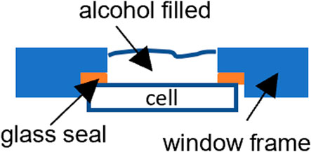
FIGURE 1. Schematic drawing showing the leak test of a planar cell glass sealed onto a metal window frame.
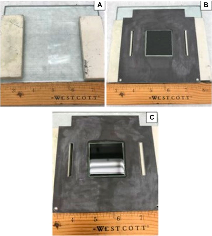
FIGURE 2. Room temperature leak test of a sealed cell/window frame assembly: (A) a flat glass plate with two spacers; (B) a sealed cell/cell frame assembly with cathode cavity facing up; (C) central cavity filled with iso-propanol.
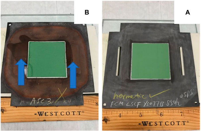
FIGURE 3. Leak test results of a sealed cell/cell frame assembly. Observation at anode side after ∼5 min of iso-propanol exposure at cathode side: (A) a satisfactory seal where no iso-propanol was observed; (B) a failed seal where iso-propanol was observed at anode side (arrows).
Room temperature leak test of tubular cells
One can apply the same alcohol leak test concept to tubular cells. Figure 4 shows the typical sealing geometry of a tubular cell in a metallic manifold plate. The leak test requires a glass, plastic, or metal pipe with an inner diameter larger than the outer diameter of the ceramic tube. The length of the pipe could be just 1–2 inches and the thickness could be several mm for easy handling. The pipe end edges need to be flat so that one can apply vacuum grease and press it down to the manifold plate with a ceramic tube inside to stop the leakage of isopropanol. The leak test can then be conducted similar to the window frame plate (i.e., planar cell) test by filling the pipe’s annular space with the alcohol to a half to one inch height. Wait 3–5 min and visually check the bottom of the manifold plate for signs of isopropanol.
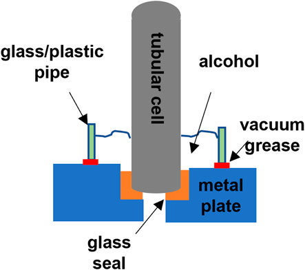
FIGURE 4. Schematic drawing of the leak test for tubular cells.
High temperature leak test by cross-bubbling for an un-reduced cell
The following leak test procedures are for a generic single cell stack fixture test consisting of an assembled cell/window frame with interconnect plates and gas manifold or compressive loading plates. Figure 5 shows the simplified schematic drawing of the setup where a cell glass-sealed to the window frame plate is sandwiched with two interconnect plates on either side with perimeter seals. Current collector and contact materials at the anode and cathode are not shown. The same principle could be extended to short stacks consisting of 3-5 cells. A full view of a typical generic stack test is shown in Figure 6A. The cell is under compressive loading and the fuel and air exhaust are immersed in the water bubblers (Figure 6, B). A zoomed in view of the bubbler is included in Figure 6C. After the final stack firing is conducted to bond the contact materials, the cell is cooled to the operating temperature (e.g., 800°C), and the following procedure is used to conduct the leak test with air in both channels (before fully reducing the anode):
1. Apply air to the cell at a reasonable flow rate through the air channel with no gas flowing in the fuel side. A typical air flow rate for a 2 inch × 2 inch LSM-based anode-supported YSZ thin electrolyte cell with an active cathode area of 16 cm2 is generally 800–900 sccm. To minimize potential thermal shock, the air flow rate should be increased gradually from zero to the target (e.g., over a period of ∼30 min)
2. Adjust the water height above the immersed end of the gas tubing to about 0.2–0.5 inch in both bubblers. This provides a suitably low resistance for bubbling.
3. Bubbling in the exhaust fuel bubbler indicates leakage caused by (1) cell to cell frame glass seal failure, (2) cell fracture (sometimes caused by flattening of the warped cell frame under the stack’s compressive loading), or (3) perimeter mica seal failure, if a compressive seal is used as the perimeter seal. Note that it is not common to observe cross-bubbling if the only leakage is through the perimeter mica seal. This is because the leakage through the compressed mica is rather small (Chou et al., 2002), and does not typically contribute to cross bubbling based on our experience of testing over 300 individual cells.
4. Shut down the air flow and wait for any observed bubbling to stop. Depending on the overall gas tubing length, it may take several minutes.
5. Turn on gas flow in the fuel side while no air flows in the other side, in a similar manner to step 1.
6. Watch for cross-bubbling in the exhaust air bubbler, which is indicative of a leak.
7. The cell may still be operable if the cross-bubbling is very minute (e.g., one bubble per second or less when the outer diameter of the metal tubing inside the bubbler is 1/8 inch). One can further repeat the test by increasing the water height from 0.2 to 0.5 inch to about 3–4 inch (typical water height for SOFC/SOEC operation) to observe if the bubbling frequency decreases. If the bubbling decreases, one may still use the cell.
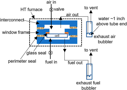
FIGURE 5. Schematic drawing of the setup for high-temperature leak test by cross-bubbling.
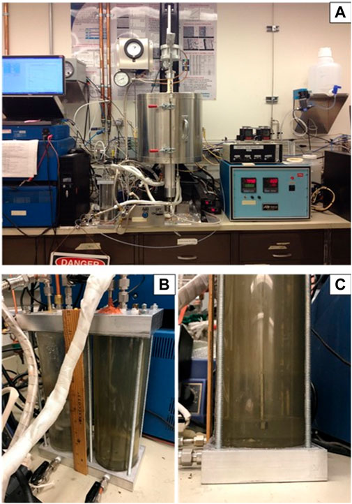
FIGURE 6. Actual set up for a generic stack test, (A) full view of the experimental set-up, (B), view of the two exhaust water bubblers (one for fuel and one for air), and (C), enlarged side view of the bubbler with ∼0.2–0.5 inch of water above the tubeing end.
High temperature leak test by OCV for a fully reduced cell
In addition to the cross-bubbling method to detect cell leakage in an unreduced cell, one can also use the open circuit voltage as an alternative leak test for single cells and short stacks that have been fully reduced. In stacks, the voltage loss due to a single cell leak (which could be 20 mV) may be too small to detect in the presence of 10 + additional cells, when the overall voltage could be above 10 V. Such a small voltage deviation (20 mV vs. 10 V) could also come from temperature variations between cells. To overcome this potential uncertainty, one needs to have voltage leads for each individual cell or for subsets of 2-3 cells to reduce the likelihood of significant temperature gradients and their effects on overall voltage. Once the cell is fully reduced, flow the desired fuel (e.g., H2:N2 = 1:1 + 3% H2O) and air at reasonable flow rates. For example, for a 2 inch × 2 inch cell with an active cathode area of 4 cm × 4 cm, one can flow 450 sccm of hydrogen fuel to the anode and 900 sccm of air to the cathode. Depending on the system and furnace, it may take some time to reach this final flow rate in order to minimize the potential for thermal shock. Once the flow rate has stabilized for 30 min, and cell temperature remains constant, one can then measure the OCV to determine whether there is a leak by comparing the measured OCV with the calculated Nernst voltage at the specified temperature and oxygen partial pressures in the fuel and air (dry or moist). If the measured OCV is more than 20 mV lower than the Nernst voltage, it is likely that some leakage is occurring. Table 1 lists the calculated Nernst voltage for hydrogen fuel (pure or diluted with N2) with 3% moisture versus air at 700, 750, and 800°C. This information can also be used to confirm the afore-mentioned cross-bubbling technique. It needs to be noted that, if one would also like to run a cross-bubbling test after the cell anode is fully reduced, care must be taken to avoid potential explosion or cell damage resulting from the mixing of air and fuel due to leakage.
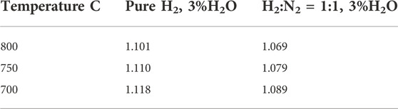
TABLE 1. Nernst voltage for hydrogen fuel (pure H2 or H2:N2 = 1:1) with 3% moisture versus air at various temperatures.
Quality control and quality assurance section
In room temperature leak tests with the alcohol penetration method and in high temperature leak tests with the cross-bubbling method, no quality control is required; all observations are visual. In high temperature leak tests using the OCV measurement technique, one would need to calibrate the analytical electrochemical characterization equipment (an impedance spectrometer or a multimeter) using appropriate calibration standards as suggested by the equipment manufacturer. In addition to the voltage measurement, an accurate measurement of cell temperature is vital in the OCV method. An external type K or S thermocouple is often placed near the cell to ensure the correct temperature is obtained for the Nernst equation calculations. The calibration of the external type K or S thermocouples can be obtained from the manufacturer.
Results
Scope and applicability
The proposed room temperature leak test by alcohol penetration is for typical planar cells sealed to a coated metallic window frame. This method is simple, fast, economical, and non-destructive. It is not a quantitative method, however. It does not require special training, expensive equipment, or constant calibrations. The results are easy to interpret without ambiguity as indicated by the arrows in Figure 2B, where the wet stains of alcohol on the anode side are obvious. In this case, leaks were present in both the glass seal (top arrow) and the cell (lower arrow). The concept is also applicable to tubular cells; however, the procedures may require minor modifications to accommodate differences in tubular designs and seal configurations. The high temperature cross-bubbling method is most suitable for a planar single cell geometry and could also be applicable to short stacks. It is most desirable to check the leakage in un-reduced cell/stack conditions where no safety or fire hazard needs to be considered since one can use air on both electrodes. The results are fast and can be semi-quantitative, meaning one can estimate the leak rate by counting the number of bubbles per minute with a known tubing inner diameter. The correlation of cross-bubbling to the leak rate is often very clear when the bubbling frequency is high (e.g., several bubbles per second) in the other channel’s bubbler. This method is not applicable to tubular designs unless all the tubes are enclosed in another pipe with a hermetic seal. The OCV technique is most suitable for planar single cells and may be extended to short stacks with voltage leads on subsets of adjacent cells such that the voltage drops from single cell leakage can be easily resolved from those resulting from temperature gradients.
Health and safety warning
Room temperature leak tests using alcohol need to be conducted in a ventilated space and away from open flames. For safety it is preferred they be conducted in a ventilated hood. All high temperature leak tests require hot surface hazard training. The OCV method also requires proper training for handling flammable gases at elevated temperatures and the emergency shut down procedure.
Cautions
In room temperature leak tests with alcohol, the sealed cell to window frame plate needs to be handled with care since the glass seal and the ceramic cell are generally brittle if the sample is dropped or carelessly handled. In addition, the thin window frame plate may warp slightly after high temperature sealing. Avoid pressing on the window frame plate when placing it on the glass plate for the room temperature alcohol penetration test.
Discussion
For the SOFC/SOEC to operate, one needs to make sure there are no leaks, especially through the cell to window frame plate seal. Early leak detection before stack assembly is more desirable and economical. This protocol introduced three methods to assess leakage: room temperature alcohol penetration, high temperature cross-bubbling, and high temperature OCV measurements. Among them, the first two are fast, with very little ambiguity. The high temperature OCV method is applicable to fully reduced single cells and stacks. The authors have not applied the high temperature OCV method to stacks with a large number of cells and, therefore, could not establish the experimental uncertainty related to this technique. For materials and process development using single cells, the leak tests presented in this protocol would be sufficient to assess leakage. However, new techniques may be required for large full-sized stacks.
Data availability statement
The original contributions presented in the study are included in the article/supplementary materials, further inquiries can be directed to the corresponding author/s.
Author contributions
YC and JH contributed to conception and design of test method. YC and OAM organized the test results and analysis. YC wrote the first draft of the manuscript. All authors contributed to manuscript revision, read, and approved the submitted version.
Funding
This work was funded by the U.S. Department of Energy Solid Oxide Fuel Cell Core Technology Program. Pacific Northwest National Laboratory is operated by Battelle Memorial Institute for the US Department of Energy under Contract no. DE-AC06-76RLO 1830.
Conflict of interest
The authors declare that the research was conducted in the absence of any commercial or financial relationships that could be construed as a potential conflict of interest.
Publisher’s note
All claims expressed in this article are solely those of the authors and do not necessarily represent those of their affiliated organizations, or those of the publisher, the editors and the reviewers. Any product that may be evaluated in this article, or claim that may be made by its manufacturer, is not guaranteed or endorsed by the publisher.
References
Chou, Y-S., Stevenson, J. W., and Chick, L. A. (2002). Ultra-low leak rate of hybrid compressive mica seals for solid oxide fuel cells. J. Power Sources 112 (1), 130–136. doi:10.1016/s0378-7753(02)00356-7
Chou, Y-S., Stevenson, J. W., and Gow, R. N. (2007). Novel alkaline Earth silicate sealing glass for SOFC: Part I. The effect of nickel oxide on the thermal and mechanical properties. J. Power Sources 168 (2), 426–433. doi:10.1016/j.jpowsour.2007.03.039
Fergus, J. W. (2005). Sealants for solid oxide fuel cells. J. Power Sources 147, 46–57. doi:10.1016/j.jpowsour.2005.05.002
Gunawan, S., Setiawan, I., and Setyawan, I. (2021). Progress in glass-ceramic seal for solid oxide fuel cell technology. J. Adv. Res. Fluid Mech. Therm. Sci. 82 (1), 39–50. doi:10.37934/arfmts.82.1.3950
Lessing, P. A. (2007). A review of sealing technologies applicable to solid oxide electrolysis cells. J. Mat. Sci. 42, 3465–3476. doi:10.1007/s10853-006-0409-9
Sang, S., Li, W., Pu, J., and Jian, L. (2008). Novel Al2O3-based compressive seals for IT-SOFC applications. J. Power Sources 177 (1), 77–82. doi:10.1016/j.jpowsour.2007.10.085
Simner, S. P., and Stevenson, J. W. (2001). Compressive mica seals for SOFC applications. J. Power Sources 102 (1-2), 310–316. doi:10.1016/s0378-7753(01)00811-4
Singh, K., and Walia, T. (2021). Review on silicate and borosilicate-based glass sealants and their interaction with components of solid oxide fuel cell. Int. J. Energy Res. 45, 20559–20582. doi:10.1002/er.7161
Weil, K. S., Hardy, J. S., and Kim, J. Y. (2003). Use of a novel ceramic-to-metal braze for joining in high temperature electrochemical devices. J. Adv. Specialty Mater. V, Am. Soc. Metals 5, 47–55.
Nomenclature and definitions
RT room temperature
HT high temperature
LSM lanthanum strontium manganate
YSZ yttrium stabilized zirconia
SOFC solid oxide fuel cell
SOEC solid oxide electrolysis cell
OCV open circuit voltage
sccm standard cubic centi-meter per minute
Keywords: SOFC and SOEC, leak test, seal quality, cell wetting by alcohol, OCV, method
Citation: Chou Y-S, Hardy J and Marina OA (2022) Leak test for solid oxide fuel cells and solid oxide electrolysis cells. Front. Energy Res. 10:945788. doi: 10.3389/fenrg.2022.945788
Received: 16 May 2022; Accepted: 24 August 2022;
Published: 05 December 2022.
Edited by:
Vânia Oliveira, Faculty of Engineering, University of Porto, PortugalReviewed by:
Kevin Huang, University of South Carolina, United StatesMiguel A Laguna-Bercero, University of Zaragoza, Spain
Copyright © 2022 Chou, Hardy and Marina. This is an open-access article distributed under the terms of the Creative Commons Attribution License (CC BY). The use, distribution or reproduction in other forums is permitted, provided the original author(s) and the copyright owner(s) are credited and that the original publication in this journal is cited, in accordance with accepted academic practice. No use, distribution or reproduction is permitted which does not comply with these terms.
*Correspondence: Yeong-Shyung Chou, eWVvbmctc2h5dW5nLmNob3VAcG5ubC5nb3Y=