 Lijian Shi
 Yuhang Jiang1
- 1College of Hydraulic Science and Engineering, Yangzhou University, Yangzhou, China
- 2Hydrodynamic Engineering Laboratory of Jiangsu Province, Yangzhou, China
- 3Jiangsu Hydraulic Research Institute, Nanjing, China
- 4Jiangsu Pumping Station Technology Co.,Ltd., of South-to-North Water Diverslon Project, Yangzhou, China
The full-tubular pump is a new type of pump with a narrow range of stable operation. In order to improve the internal flow characteristics of the full-tubular pump under small flow conditions and improve the safe and stable operating range of the pump, this paper conducts numerical simulation of the full-tubular pump model based on the Reynolds time-averaged N-S equation and the SST k-ω turbulence model. The improvement mechanism of the parameters of the inlet grooves on the stall area of the full-tubular pump is studied, and the reliability of the numerical simulation of the full-tubular pump is verified by model tests. The research results show that the inlet groove can improve the head and efficiency of the full-tubular pump in the small flow area, and the head at the deep stall condition is increased by nearly 1.61 m. The inlet groove increases the pressure difference of the impeller, which increases the head and improves the hump. At the same time, the increase in the pressure difference of the impeller increases the backflow flow in the gap between the stator and the rotor. The groove can reduce the vortex strength and backflow range at the inlet pipe wall near the stall operating, and also improve the flow field at the impeller inlet. In terms of pressure pulsation, the groove can effectively suppress the low-frequency pressure pulsation at the inlet of the impeller of the full-tubular pump under stall conditions, and effectively reduce the amplitude of the main frequency pressure pulsation and improve the internal flow. The research in this paper can provide a reference for improving the flow characteristics in the stall condition of the full-tubular pump.
Introduction
Every pump has an optimal working condition area. Once it deviates from this area, it will affect the performance of the pump. Especially in the area of small flow conditions, it is easy to generate a saddle zone. The flow state at this working conditions is unstable, which seriously affects the performance and service life of the pump. It is not conducive to the safe and stable operation of the pump. As a new type of mechatronics pump, the full-tubular pump (Tang et al., 2012; Yang et al., 2012; Liu, 2015) has the advantages of compact structure, convenient installation and stable operation, but it has a more obvious saddle zone (Li et al., 2018; Gs et al., 2020; Zhang et al., 2021; Zhang and Tang, 2022) than the axial-flow pump in the area of small flow conditions. Shi et al. (Shi et al., 2020; Shi et al., 2021a; Shi et al., 2021b) analyzed the backflow clearance of the full-tubular pump and found that when the clearance is constant, as the flow rate of the impeller decreases, the backflow of the clearance increases and the closer it is to the rim, the greater the influence of backflow. In terms of pressure pulsation, Zhang et al. (2017a); and Zhang et al. (2017b) found that under different working conditions, the main frequency of the pressure pulsation at the inlet and outlet of the impeller is the blade frequency, and the main frequency of the guide vane changes with the flow.Kan et al. (2018); Kan et al. (2021a) studied the internal flow of the axial-flow pump under the stall condition, and used the Q-criterion to study the evolution law of the guide vane vortex structure core under the deep stall condition. It is found that the evolution law of the vortex core area is basically the same as the streamline diagram of the guide vane and the low frequency pressure pulsation is caused by the vortex in the guide vane.Zheng et al. (2011); Zheng et al. (2017) analyzed the flow characteristics of the axial-flow pump under small flow conditions, and found that there is backflow at the front edge of the back of the blade near the rim and the trailing edge near the hub under stall conditions.Chen et al. (2012) analyzed the impeller inlet flow field of an axial-flow pump under small flow conditions, and found that the secondary backflow in the pump would lead to inlet pre-swirl, which is reflected in the saddle zone in the performance curve. At present, the improvement methods (Zhang et al., 2013; Wang et al., 2020a; Kan et al., 2021b; Wang et al., 2022) in the area of small flow conditions include slitting the impeller blades, adding front guide vanes, and applying grooves in the wall of inlet pipe. Wang et al. (2016) studied the slit at the impeller inlet of a centrifugal pump and found that the slit at the blade inlet can improve the cavitation performance of the centrifugal pump, and the energy distribution in the impeller channel is more uniform after slitting. Qu et al. (2021) added a bracket at the inlet water guide cone of the axial-flow pump, and found that the inlet water guide cone bracket effectively suppressed the range and intensity of the backflow vortex, and reduced the low-frequency pressure fluctuation, improving the stability of the overall pump device. As for the groove (Saha et al., 2000; Zhang and Chen, 2014; Feng et al., 2018; Wang et al., 2020b; Mu et al., 2020) of the inlet pipe, many scholars at home and abroad have made grooves on the inlet pipe wall of the axial flow pump and mixed flow pump. They found that the axial groove can reduce the back flow of the blade, improve the hump of the pump, and improve the head and efficiency of small flow conditions.
In this paper, according to the flow instability characteristics of the full-tubular pump under small flow conditions, the internal flow mechanism is revealed and the influence of the grooves on the inlet pipe wall on the performance of the full-tubular pump will be explored. The influence of the geometrical parameters of the grooves on the head and efficiency of the full-tubular pump was explored, and the optimal scheme was selected to compare with the original scheme, and the improvement effect of the grooves on the stall condition of the full-tubular pump was explored.
1 Numerical Calculation
1.1 Calculation Model
The full-tubular pump model used in this paper does not consider the coil arrangement. The impeller diameter (D1) is 350mm, the number of blades is 4, the backflow gap between the stator and rotor of the full-tubular pump is 0.65mm, the speed (ns) is 950r/min, and the hub ratio (dh1) is 0.4. The diameter (D2) of the guide vane is 350mm, the number of blades is 7, and the hub ratio (dh2) is 0.4. The three-dimensional calculation model of the full-tubular pump is shown in Figure 1, including the inlet pipe, impeller, motor rotor, guide vane and the outlet pipe. Axial grooves are uniformly distributed at the outlet of the inlet pipe near the impeller. The number of axial grooves is 40, the groove length is L (L/D1 = 0.67), that is, the groove length is 230 mm.
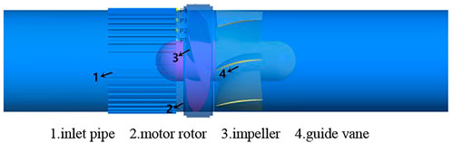
FIGURE 1. 3D model of numerical calculation of full-tubular pump.
1.2 Meshing and Mesh Independence Verification
The model grid of the computational domain adopts the block drawing method. The impeller and guide vane are imported into Turbo-Grid for modeling and dividing the structured grid. The number of impeller grids is about 600,000, and the number of guide vane grids is about 800,000. The grooved inlet pipe and the motor rotor are modeled by UG, and the unstructured grid is divided by ICEM and the grid of the pipe wall is refined. The number of grids is about 700,000 and 1,700,000 respectively, the grid quality is above 0.5, and the y + value of each part of this paper is controlled within 100 to meet the calculation requirements. The grid diagram of the main components of the calculation model of the full-tubular pump is shown in Figure 2.
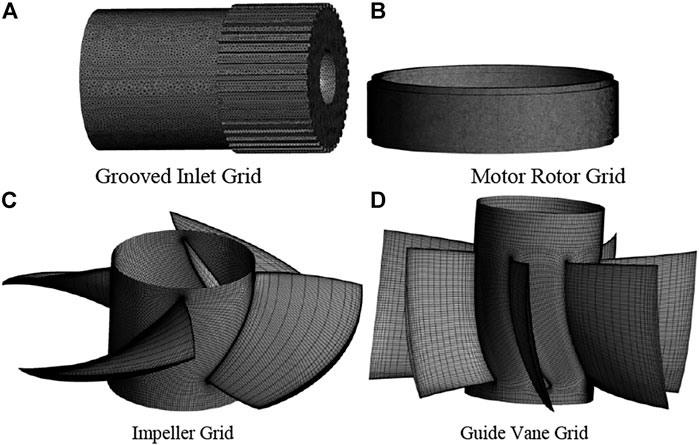
FIGURE 2. Meshing of the main components of the computational domain. (A) grooved inlet grid, (B) motor rotor grid, (C) impeller grid, (D) guide vane grid.
In order to avoid the influence of the number of grids on the calculation results, the grid-independent analysis of the calculation domain was carried out in the design condition (Qd = 390L/s). As shown in Figure 3, it can be found that when the total number of grids is from 4.2 million to 8 million, the increase in the number of grids has little effect on the efficiency of the full-tubular pump. In order to save computing resources and reduce the total calculation time, the total number of grids was finally selected as 4.2 million for further numerical calculation of the full-tubular pump.
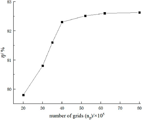
FIGURE 3. Grid-independent analysis of computational domain of the full-tubular pump.
1.3 Governing Equations and Boundary Conditions
In this paper, ANSYS CFX is used to carry out the numerical calculation of the full-tubular pump. The control equation adopts the time-averaged Navier-Stokes equation, and the turbulence model adopts the SST k-ω turbulence model. The turbulence model has high predictability in terms of internal flow and external energy characteristics. Especially for the flow separation under the adverse pressure gradient, it has high prediction accuracy.
The continuity equation is:
The Navier-Stokes equation is:
Where ui is fluid the velocity, ρ is the fluid density, fi is mass force, p is pressure intensity, u is dynamic viscosity, and xi and xj are position vectors.
The turbulent eddy viscosity ut, the turbulent energy k equation and the turbulent eddy frequency ω equation are as follows:
Where k is the turbulent kinetic energy, ω is the turbulent frequency, ρ is the fluid density, Uj is the velocity vector, Pk is the production rate of turbulence, xj is position vectors, The model constants are given by: β1 = 0.09, α1 = 5/9, β = 0.075, σk1 = 2, σω1 = 2.
The boundary conditions are: the inlet is set to total pressure and the pressure is 1 atm; the outlet is set to mass-flow, and the design flow is 390L/s; the flow is incompressible and the density is constant everywhere; the flow-passing part adopts a smooth non-slip wall. Set the impeller and rotor as rotating domains and the other computational domains as stationary domains. At the same time, for the unstable stall condition, this paper conducts an unsteady calculation of the flow field inside the full-tubular pump. The dynamic and static interface is set to Transient Rotor Stator, the time step is set to 5.2632 × 10⁻⁴s, each time step the impeller rotates 3°.
2 Model Test and Scheme Selection
2.1 Numerical Reliability Verification
Numerical simulation is carried out on the calculation model of the initial full-tubular pump without the grooved inlet pipe in Figure 1, and compared with the existing model experiments. In this paper, the model test of the full-tubular pump is carried out on the high-precision vertical closed-cycle hydraulic mechanical test bench. The actual test picture is shown in Figure 4.
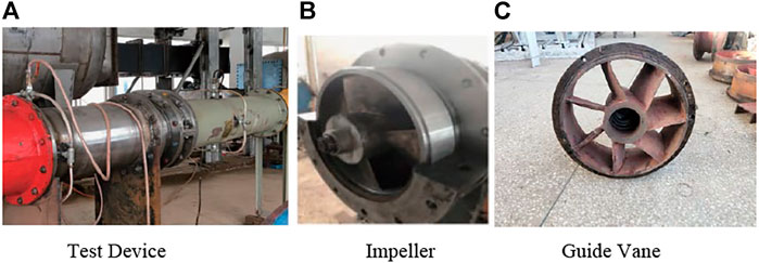
FIGURE 4. Model pump device. (A) test device, (B) impeller, (C) guide vane.
The test refers to the relevant model test procedures, and the external characteristics experiment of six blade placement angles is carried out on a full-tubular pump with a clearance of 0.65 mm. Each placement angle has at least 18 test points. In this paper, the blade placement angle is 0°for comparative research.
According to the comparison in Figure 5, it can be seen that the flow-head curve of the test and numerical simulation of the full-tubular pump is in good agreement near the design condition, and the maximum head error value is 0.23 m under the small flow condition (Q/Qd = 0.62); The flow-efficiency curve has a high degree of agreement near the small flow condition. The experimental efficiency under the design condition is 78.83%, the numerical simulation efficiency is 82.24%, and the error value is 3.41%. The head and efficiency errors are within the allowable range and meet the calculation accuracy requirements. Through the comparison between the test and the numerical simulation of the full-tubular pump, it shows that the numerical simulation (Kan et al., 2020) of the full-tubular pump in this paper is accurate and credible.
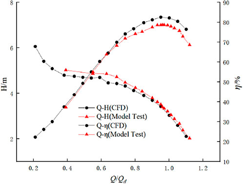
FIGURE 5. Model test and numerical simulation comparison.
2.2 Influence of Inlet Groove Parameters on Hydraulic Performance of Full-Tubular Pump
In this paper, the number of grooves n, the groove length L and the groove depth h are respectively studied to explore the degree of improvement of the saddle zone of the full-tubular pump with different groove parameters, and select the optimal solution for analysis. Take the number of grooves n = 40, 60, the groove length L/D1 = 0.33 and 0.67, and the groove depth h/D1 = 0.01, 0.02, 0.03 for comparison. The specific parameter corresponding scheme is shown in Tab.1.
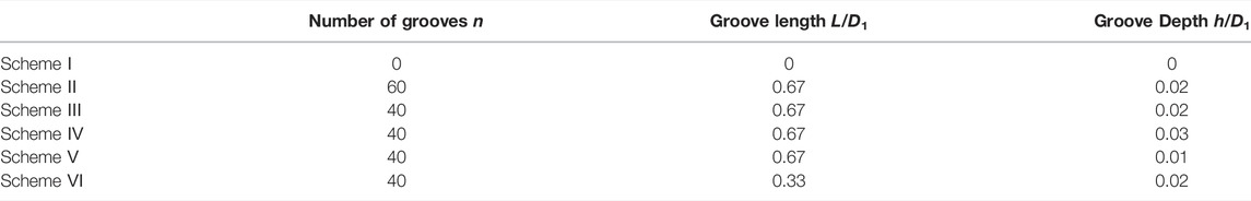
TABLE 1. Schemes of inlet grooves of different full-tubular pumps.
According to Figure 6, it can be found that the flow-head curve of scheme Ⅰ has a long flat section with the decrease of the flow rate in the small flow condition, indicating that the pump has entered the stall area operation at this time. After the inlet pipe is grooved, it is found that the saddle zone is significantly improved in this working condition, the flat head section basically disappears, and the efficiency is improved under the small flow conditions. Compared with other groove parameters, the length of the groove has the greatest influence on the head of the full-tubular pump, and when the number of grooves and the groove length are constant, the groove depth of 0.02 is better. Among all the schemes, scheme Ⅲ is the best, which is embodied in: in terms of head, the head near the deep stall condition (Q/Qd = 0.40) is about 1.61 m higher than scheme one; In terms of efficiency, it is about 1.5% smaller than that of scheme Ⅰ near the design flow, but the efficiency is improved by about 2.2% under small flow conditions. By comparison, this paper selects the original scheme, scheme Ⅰ, and the optimal scheme, scheme Ⅲ, to analyze the internal flow field.
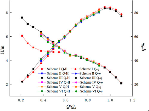
FIGURE 6. Performance curves under different groove parameters.
Computational Results and Analysis
Variation of Static Pressure of Full-Tubular Pump
In order to analyze the influence of grooves on the working performance of each component of the full-tubular pump, Figure 7B describes the pressure difference changes of the full-tubular pump under the conditions of Q/Qd = 0.40 and Q/Qd = 0.62. The central cross section of the impeller blade is taken as the reference plane, and the direction of the water flow is positive, D1 is the diameter of the impeller, and X/D1 represents the relative position to the reference plane, as shown in Figure 7A. ΔH represents the static pressures between the cross section of the corresponding relative position and the inlet, and the specific formula is as follows:

FIGURE 7. Variation of hydraulic performance in different computational domains.
It can be seen from the Figure 7B that when Q/Qd = 0.62, the changes of the pressures between the two schemes are almost the same, indicating that the groove has no effect on the performance of the full-tubular pump before entering the saddle zone, that is, when the stall does not occur. When the full-tubular pump is in deep stall Q/Qd = 0.40, it can be found that the pressure difference value of scheme Ⅲ in the impeller area is 1.32 times that of scheme Ⅰ, indicating that the groove greatly improves the pressure difference in the impeller area. This can also explain why the head of the groove schemes in Figure 6 has a significant increase in the saddle zone. The negative pressure area of scheme Ⅰ in the inlet pipe area is significantly higher than that of scheme Ⅲ, indicating that scheme Ⅰ has a longer backflow. In the guide vane area, the variation law of the pressure difference between the two schemes is almost the same.
Analysis of Inlet Pipe Flow Field
In order to analyze how grooving affects the hydraulic characteristics of the full-tubular pump, the axial velocity cloud diagrams and streamline diagrams of the inlet pipe and impeller under two different working conditions (Q/Qd = 0.62, 0.40) in the saddle zone are taken in this paper, as shown in Figure 8. Through comparison, it can be found that when Q/Qd = 0.62, there is no obvious difference in the flow state of the inlet pipe of the two schemes, indicating that the groove does not affect the flow state of the design condition. In the deep stall condition, the velocity distribution of the inlet pipe of scheme Ⅰ is uneven, and the velocity gradient changes greatly at the impeller inlet. In scheme Ⅲ, it is obvious that the velocity distribution of the inlet pipe is uniform, and the velocity gradient of the impeller inlet is slowed down, which also explains why the groove can increase the head and efficiency of the full-tubular pump under small flow conditions. It can also be found that in the case of deep stall conditions (Q/Qd = 0.40) in scheme Ⅰ, there are obvious vortices and backflows at the impeller inlet near the wheel rim, which seriously squeeze the flow state of the inlet pipe, especially at the side wall of the inlet pipe. From Figure 8D, we can see that the groove effectively reduces the vortex strength and backflow range of the full-tubular pump under stall conditions, and the flow pattern of the inlet pipe is significantly improved compared with the scheme Ⅰ.
FIGURE 8. Internal flow characteristics of the inlet pipe and impeller of the full-tubular pump. (A) Scheme Ⅰ Q/Qd=0.62, (B) Scheme Ⅰ Q/Qd=0.40, (C) Scheme ⅠII Q/Qd=0.62, (D) Scheme ⅠII Q/Qd=0.40.
Since the backflow gap in the full-tubular pump has a great influence on the hydraulic characteristics of the impeller, for the vortex and backflow changes when Q/Qd = 0.40, this paper analyzes the effect of grooves on the gap flow characteristics under this working condition. It can be seen from Figure 9 that since the backflow flow in the gap flows from the rim of the impeller outlet to the rim of the inlet of the impeller, there is an obvious bias flow from the outlet of the impeller to the rim of the impeller in scheme Ⅰ. In the scheme Ⅲ, the pressure at the backflow inlet of the gap increases due to the groove, so that the bias flow phenomenon at the outlet of the impeller is improved.
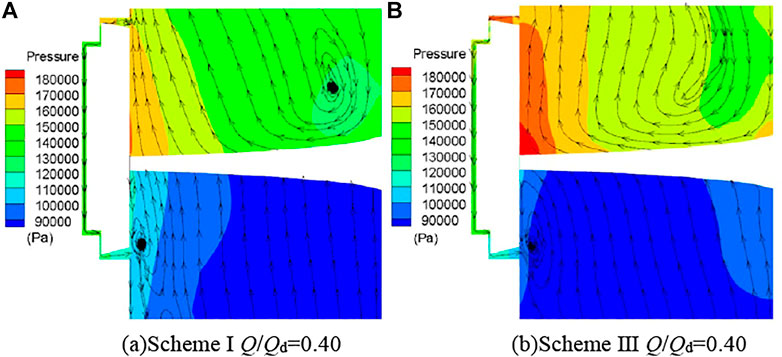
FIGURE 9. Characteristics of internal flow in the gap of the full-tubular pump. (A) Scheme Ⅰ Q/Qd = 0.40 (B) Scheme Ⅲ Q/Qd = 0.40.
As shown in Figure 10, the gap backflow of scheme Ⅰ increases gradually as the flow rate decreases, and the pressure difference between the inlet and outlet of the impeller also gradually increases. However, when Q/Qd = 0.62, the backflow begins to decrease, and the growth of the inlet and outlet pressure difference begins to slow down. However, the backflow in the gap of scheme Ⅲ keeps increasing as the flow rate decreases, and the pressure difference between the inlet and outlet of the impeller still increases rapidly when Q/Qd = 0.62 due to the groove. The increase in the pressure difference between the inlet and outlet of the impeller increases the head of the full-tubular pump behind the groove in the stall condition, and at the same time, the gap backflow at the stator and rotor also increases.
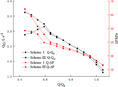
FIGURE 10. Gap backflow and pressure difference between impeller inlet and outlet under all working conditions.
Axial Velocity Uniformity of the Impeller Inlet
In order to further illustrate the degree of turbulence of the impeller inlet flow field of the two, this paper uses the axial velocity distribution uniformity to describe the quality of the impeller inlet flow state. The calculation formula is:
Where
Figure 11 shows the axial velocity uniformity of the impeller inlet under all working conditions. It can be seen that the values of scheme Ⅲ are higher than those of scheme Ⅰ. Under the design conditions (Q/Qd = 1.0), the axial velocity uniformity values of the two schemes are both higher than 92%, indicating that the grooves have no influence on the impeller inlet flow state under the design conditions and large flow conditions. When the flow rate decreases, the uniformity values of the two schemes both decrease and the decreasing trend of scheme Ⅰ is higher than that of scheme Ⅲ. When in the deep stall condition (Q/Qd = 0.40), we can see that the axial velocity uniformity value of scheme Ⅲ is increased by nearly 10%, indicating that the groove improves the flow state of the impeller inlet. This also proves the reliability of the velocity cloud diagrams and streamline diagram of the inlet pipe and impeller in Figure 8 and Figure 9.
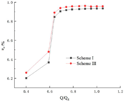
FIGURE 11. Impeller inlet axial velocity uniformity under all working conditions.
Analysis of Impeller Inlet Pressure Pulsation
The above analysis of the inlet flow field of the full-tubular pump shows that under the stall condition, there are complex flows such as vortex and secondary backflow at the impeller inlet, which may cause hydraulic excitation, and the pressure pulsation is the main manifestation of hydraulic excitation. In this paper, four monitoring points are set along the radial direction at the impeller inlet section (as shown in Figure 1 P1-4), to study the effect of grooves on the pressure pulsation of the impeller inlet of the full-tubular pump. The rotational frequency fn of the blade and the pressure pulsation coefficient Cp are cited as indicators for evaluating the internal pressure pulsation characteristics. The formula is as follows:
Where F is the actual frequency after taking the Fourier transform; n is the impeller speed; ΔP is the difference between the instantaneous pressure and the time-averaged pressure; ρ is the liquid density; u is the peripheral speed of the blade tip.
Figure 12 shows the time domain diagram of the impeller inlet pressure pulsation under the deep stall condition. The periodicity of the pressure pulsation changes in the two schemes is good. There are four obvious peaks and troughs in one rotation cycle of the impeller, which are consistent with the number of blades, which indicates that the impeller is the main factor for inducing hydraulic vibration. The pressure pulsation amplitude of scheme Ⅰ changes drastically, while the change of the pressure pulsation amplitude of scheme Ⅲ after slotting is much smaller than that of scheme Ⅰ. Figure 13 shows the frequency domain diagram of the impeller inlet pressure pulsation under deep stall conditions. It can be seen that since the circumferential speed of the impeller increases with the increase of the radius, the pressure pulsation amplitude decreases from the rim to the hub. The internal flow field of scheme Ⅰ is extremely unstable, and there is obvious low-frequency pulsation at the inlet. The main frequency of the pressure pulsation is 0.45 times the frequency and 4 times the frequency, and the amplitudes are 0.1439, 0.1324, 0.1272, 0.1154 and 0.102, 0.0984, 0.0865, 0.0732. In scheme Ⅲ, it is found that the low-frequency pressure pulsation at the impeller inlet is significantly improved, and the amplitude is nearly 6.6 times lower than that of the scheme Ⅰ. The high-frequency pulsation almost disappears, the main frequency of the pressure pulsation is 4 times the rotational frequency, and the amplitude of the blade frequency is about 3 times smaller than that of the scheme Ⅰ. The impeller inlet pressure pulsation can be obviously improved by grooving in stall condition, which proves that grooving can reduce the hydraulic excitation of the full-tubular pump in small flow condition and improve the internal flow.
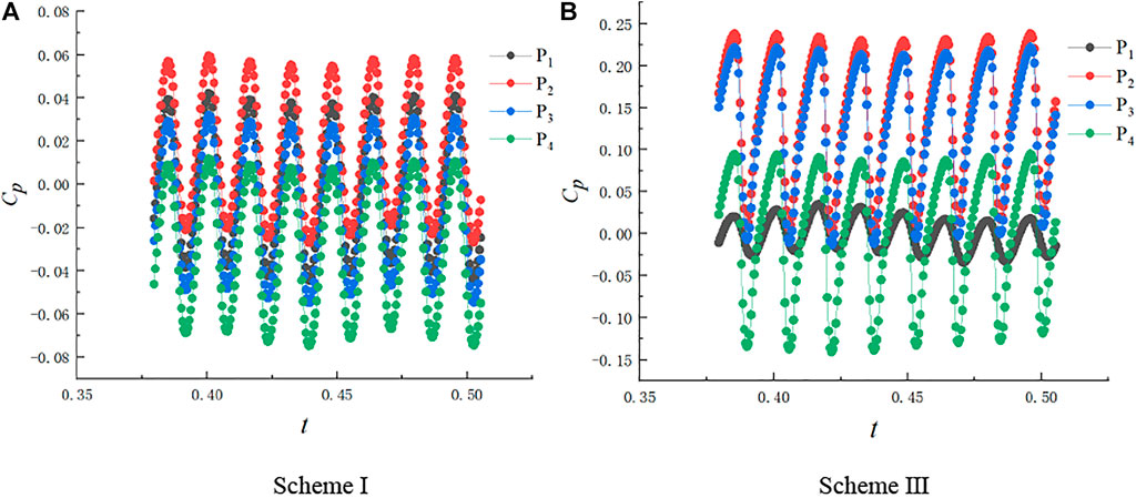
FIGURE 12. Time domain diagram of impeller inlet pressure pulsation(Q/Qd = 0.40). (A) Scheme I, (B) Scheme III.
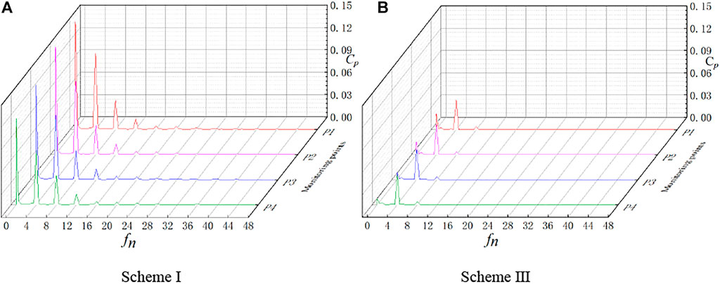
FIGURE 13. Frequency domain diagram of impeller inlet pressure pulsation(Q/Qd = 0.40).(A) scheme I, (B) scheme III.
Conclusion
This paper uses numerical simulation to study the improvement of the inlet groove on the saddle area of the full-tubular pump and its influence on the impeller inlet flow field. The specific conclusions are as follows:
1) When the flow gradually decreases, the full-tubular pump has a longer saddle zone, and the inlet groove improves the saddle zone and lifts the maximum head by 1.61 m. The groove mainly increases the pressure difference of the impeller under the condition of small flow, thereby increasing the head of the full-tubular pump.
2) When in the deep stall condition, the flow state of the full-tubular pump is extremely poor, and there are serious backflow and vortex on the pipe wall. The groove obviously reduces the backflow length and vortex range of the inlet pipe wall and improves the velocity gradient distribution at the impeller inlet. Due to the increase in head, the groove will increase gap backflow at the stator and rotor.
3) By comparing the time domain characteristics and frequency domain characteristics of the pressure pulsation between the original model and the groove model under the stall condition, the impeller inlet pressure pulsation is affected by the impeller. The groove can effectively improve the impeller inlet pressure pulsation characteristics under stall conditions, and reduce the pressure pulsation amplitude and low frequency components.
Data Availability Statement
The original contributions presented in the study are included in the article/Supplementary Material, further inquiries can be directed to the corresponding author.
Author Contributions
Conceptualization, LS and FT; methodology, YJ and YGC; software, TX and JZ; validation, LS and BC; data curation, BC and YAC; writing original draft preparation, LS, YJ and FT; writing review and editing, LS, YJ and YGC; visualization, BC and JZ; supervision, LS, YGC, and FT; funding acquisition, LS and FT; All authors have read and agreed to the published version of the manuscript.
Funding
This article was supported by the Natural Science Foundation of the Jiangsu Province of China (No. BK20190914); the China Postdoctoral Science Foundation Project (No.2019M661946); the Natural Science Foundation of Jiangsu Higher Education Institutions of China (No. 19KJB570002); the Jiangsu Water Conservancy Science and Technology project (No. 2021012); the Postdoctoral Research Fund project of the Jiangsu Province (No. 2021K360C); the Postgraduate Research Innovation Program of the Jiangsu Province (No. KYCX21_3227); the Postgraduate Practice Innovation Program of the Jiangsu Province (No. SJCX21_1585); the Priority Academic Program Development of Jiangsu Higher Education Institutions (No. PAPD).
Conflict of Interest
Author BC was employed by the company Jiangsu Pumping Station Technology Co.Ltd. of South-to-North Water Diverslon Project
The authors declare that the research was conducted in the absence of any commercial or financial relationships that could be construed as a potential conflict of interest.
Publisher’s Note
All claims expressed in this article are solely those of the authors and do not necessarily represent those of their affiliated organizations, or those of the publisher, the editors and the reviewers. Any product that may be evaluated in this article, or claim that may be made by its manufacturer, is not guaranteed or endorsed by the publisher.
References
Chen, W., Lu, L., Wang, G., and Dong, L. (2012). Influence of Axial-Flow Pump Operating Condition on the Pre-swirl at Impeller Chamber Inlet[J]. J. Hydroelectr. Eng. 31 (01), 213
Feng, J., Yang, K., Zhu, G., Luo, X., and Li, W. (2018). Elimination of Hump in Axial Pump Characteristic Curve by Adopting Axial Grooves on Wall of Inlet Pipe[J]. Trans. Chin. Soc. Agric. Eng. 34 (13), 105. doi:10.11975/j.issn.1002-6819.2018.13.013
Gs, A., Zl, A., Yx, B., Hl, A., and Xl, A. (2020). Tip Leakage Vortex Trajectory and Dynamics in a Multiphase Pump at Off-Design Condition. Renew. Energy 150, 703. doi:10.1016/j.renene.2020.01.024
Kan, K., Chen, H., Zheng, Y., Zhou, D., Binama, M., and Dai, J. (2021). Transient Characteristics during Power-Off Process in a Shaft Extension Tubular Pump by Using a Suitable Numerical Model. Renew. Energy 164, 109–121. doi:10.1016/j.renene.2020.09.001
Kan, K., Yang, Z., Lyu, P., Zheng, Y., and Shen, L. (2021). Numerical Study of Turbulent Flow Past a Rotating Axial-Flow Pump Based on a Level-Set Immersed Boundary Method. Renew. Energy 168, 960–971. doi:10.1016/j.renene.2020.12.103
Kan, K., Zheng, Y., Chen, H., Zhou, D., Dai, J., Binama., M., et al. (2020). Numerical Simulation of Transient Flow in a Shaft Extension Tubular Pump Unit during Runaway Process Caused by Power Failure. Renew. Energy 154, 1153–1164. doi:10.1016/j.renene.2020.03.057
Kan, K., Zheng, Y., Chen, Y., Xie, Z., Yang, G., and Yang, C. (2018). Numerical Study on the Internal Flow Characteristics of an Axial-Flow Pump under Stall Conditions. J. Mech. Sci. Technol. 32 (10), 4683–4695. doi:10.1007/s12206-018-0916-z
Li, D., Wang, H., Qin, Y., Wei, X., and Qin, D. (2018). Numerical Simulation of Hysteresis Characteristic in the Hump Region of a Pump-Turbine Model. Renew. Energy 115, 433–447. doi:10.1016/j.renene.2017.08.081
Liu, C. (2015). Researches and Developments of Axial-Flow Pump System[J]. Trans. Chin. Soc. Agric. Mach. 46 (06), 49. doi:10.6041/j.issn.1000-1298.2015.06.008
Mu, T., Zhang, R., Xu, H., Zheng, Y., and Li, J. (2020). Study on Improvement of Hydraulic Performance and Internal Flow Pattern of the Axial Flow Pump by Groove Flow Control technology[J]. Renewable Energy.
Qu, H., Chen, Y., Tang, F., Zhang, W., Liu, H., Bai, Z., et al. (2021). The Impact of the Inlet Water Guide Cone Bracket on Function of the Saddle Zone in Vertical Axial-Flow Pump[J]. J. Irrigation Drainage 40 (7), 97. doi:10.13522/j.cnki.ggps.2020694
Saha, S. L., Kurokawa, J., Matsui, J., and Imamura, H. (2000). Suppression of Performance Curve Instability of a Mixed Flow Pump by Use of J-Groove. J. Fluids Eng. 122 (3), 592–597. doi:10.1115/1.1287855
Shi, L., Jiao, H., Gou, J., Yuan, Y., Tang, F., and Yang, F. (2020). Influence of Backflow Gap Size on Hydraulic Performance of Full-Flow Pump[J]. Trans. Chin. Soc. Agric. Mach. 51 (04), 139. doi:10.6041/j.issn.1000-1298.2020.04.016
Shi, L., Zhu, J., Wang, L., Chu, S., Tang, F., Jiang, Y., et al. (2021). Analysis of Strength and Modal Characteristics of a Full Tubular Pump Impeller Based on Fluid-Structure Interaction[J]. Energies, 14. doi:10.21203/rs.3.rs-627588/v1
Shi, L., Zhu, J., Yuan, Y., Tang, F., Huang, P., Zhang, W., et al. (2021). Numerical Simulation and Experiment of the Effects of Blade Angle Deviation on the Hydraulic Characteristics and Pressure Pulsation of an Axial-Flow Pump. Shock Vib. 2021 (6), 1–14. doi:10.1155/2021/6673002
Tang, F., Liu, C., Xie, W., Yuan, J., and Cheng, L. (2012). Experimental Studies on Hydraulic Models for a Reversible, Tubular, and Submersible Axial-Flow Pump Installation[J]. Trans. Chin. Soc. Agric. Mach., 74–77.
Wang, W., Tai, G., Pei, J., Pavesi, G., and Yuan, S. (2022). Numerical Investigation of the Effect of the Closure Law of Wicket Gates on the Transient Characteristics of Pump-Turbine in Pump Mode. Renew. Energy 194, 719–733. doi:10.1016/j.renene.2022.05.129
Wang, W., Wang, W., Zhang, L., Zhao, L., Lu, J., Feng, J., et al. (2020). X Mechanism for End-Wall Slots to Improve Hump in an Axial Flow Pump[J]. Trans. Chin. Soc. Agric. Eng. 36 (23), 12–20.
Wang, W., Zhang, X., Lu, J., Luo, X., and Chu, W. (2020). Coupling Method and Mechanism of Stability Enhancement for Endwall Stall in Axial-Flow Compressor[J]. J. Propuls. Technol. 41 (03), 544. doi:10.11975/j.issn.1002-6819.2020.23.002
Wang, Y., Xie, S., and Wang, W. (2016). Numerical Simulation of Cavitation Performance of Low Specific Speed Centrifugal Pump with Slotted Blades[J]. J. Drainage Irrigation Mach. Eng. 34 (03), 210. doi:10.3969/j.issn.1674-8530.15.0009
Yang, F., Jin, Y., Liu, C., Tang, F., and Yang, H. (2012). Numerical Analysis and Performance Test on Diving Tubular Pumping System with Symmetric Aerofoil Blade[J]. Trans. Chin. Soc. Agric. Eng. 28 (16), 60. doi:10.3969/j.issn.1002-6819.2012.16.010
Zhang, D., Liu, J., Geng, L., Shi, L., and Zhang, J. (2017). Numerical Simulation and Experiment of Pressure Fluctuation in Mixed-Flow Pumps under Low Flow Conditions[J]. Trans. Chin. Soc. Agric. Mach. 48 (02), 117. doi:10.6041/j.issn.1000-1298.2017.02.016
Zhang, D., Shi, L., Zhao, R., Shi, W., Pan, Q., and Van Esch, B. P. (2017). Study on Unsteady Tip Leakage Vortex Cavitation in an Axial-Flow Pump Using an Improved Filter-Based Model[J]. J. Mech. Sci. Technol. 31, 659–667. doi:10.1007/s12206-017-0118-0
Zhang, H., Wu, J., Chu, W., Wu, Y., and Wang, W. (2013). Full-annulus Numerical Investigation of Influence on Flow-Field in an Axial Flow Compressor with Inlet Distortion[J]. J. Propuls. Technol. 34 (08), 1056
Zhang, R., and Chen, H. (2014). Study on the Improvement of Hydrodynamic Performance of Axial-Flow Pump at Stall Condition[J]. J. Hydroelectr. Eng. 33 (03), 292. doi:10.4321/S0004-05922009000400017
Zhang, X., and Tang, F. (2022). Investigation of the Hydrodynamic Characteristics of an Axial Flow Pump System under Special Utilization Conditions[J]. Sci. Rep. 12 (1), 9157. doi:10.1038/s41598-022-09157-1
Zhang, X., Tang, F., Liu, C., Shi, L., Liu, H., Sun, Z., et al. (2021). Numerical Simulation of Transient Characteristics of Start-Up Transition Process of Large Vertical Siphon Axial Flow Pump Station. Front. Energy Res. 9, 706975. doi:10.3389/fenrg.2021.706975
Zheng, Y., Chen, Y., Zhang, R., Ge, X., and Sun, A. (2017). Analysis on Unsteady Stall Flow Characteristics of Axial-Flow Pump[J]. Trans. Chin. Soc. Agric. Mach. 48 (07), 127. doi:10.6041/j.issn.1000-1298.2017.07.016
Zheng, Y., Mao, Y., Zhou, D., and Zhang, D. (2011). Flow Characteristics of Low-Lift and Large Flow Rate Pump Installation in Saddle Zone[J]. J. Drainage Irrigation Mach. Eng. 29 (05), 369. doi:10.3969/j.issn.1674-8530.2011.05.001
Nomenclature
D1 the diameter of the impeller:mm.
D2 the diameter of the guide vane:mm.
Ns the rotation speed, r/min.
dh1 the impeller hub ratio.
dh2 the guide vane hub ratio.
Lgroove length: groove length:mm.
Qd the design flow of the pump, L/s.
ρ fluid density.
hgroove depth: groove depth:mm.
n number of grooves.
k the turbulent kinetic energy.
ω the turbulent frequency.
xi a cross section.
ΔH the pressure difference between a cross section and the inlet pipe.
Pxi static pressure of a cross section, kPa.
Pinlet static pressure of the inlet pipe, kPa.
QG gap backflow, L/s.
ΔP the pressure difference between the inlet and outlet of the impeller, kPa.
fn the rotational frequency of the blade.
Cp the pressure pulsation coefficient.
Keywords: stall condition, numerical simulation, gap backflow, hydraulic performance, model test, full-tubular pump
Citation: Shi L, Jiang Y, Cai Y, Chen B, Tang F, Xu T, Zhu J and Chai Y (2022) Influence of Inlet Groove on Flow Characteristics in Stall Condition of Full-Tubular Pump. Front. Energy Res. 10:949639. doi: 10.3389/fenrg.2022.949639
Received: 21 May 2022; Accepted: 13 June 2022;
Published: 05 July 2022.
Edited by:
Kan Kan, College of Energy and Electrical Engineering, ChinaReviewed by:
Tianyi Li, University of Minnesota Twin Cities, United StatesWenjie Wang, Jiangsu University, China
Copyright © 2022 Shi, Jiang, Cai, Chen, Tang, Xu, Zhu and Chai. This is an open-access article distributed under the terms of the Creative Commons Attribution License (CC BY). The use, distribution or reproduction in other forums is permitted, provided the original author(s) and the copyright owner(s) are credited and that the original publication in this journal is cited, in accordance with accepted academic practice. No use, distribution or reproduction is permitted which does not comply with these terms.
*Correspondence: Lijian Shi, c2hpbGlqaWFuQHl6dS5lZHUuY24=