 Yongliang Zhang
 Nansheng Xu1
 Kevin Huang
- 1Department of Mechanical Engineering, University of South Carolina, Columbia, SC, United States
- 2Hydrogen and Fuel Cell Technologies Office, United States Department of Energy, Washington, DC, MD, United States
Water/steam electrolysis is a key enabling technology for clean, low-carbon and sustainable production of hydrogen and will play a crucial role in future hydrogen economy. For high temperature solid oxide electrolytic cells, steam is the chemical feedstock. A stable and accurate supply of steam to solid oxide electrolytic cells is of vital importance to smooth production of hydrogen. In this study, we compare steam supply performance of two commonly used steam generators: steamer and bubbler. Our results show that bubbler with proper volume and fritted inlet gas tubing can provide more stable and accurate steam supply than steamer for laboratory use. We also provide the explanation for the unstable steam supply observed in steamer. Overall, we conclude that bubbler is generally a better choice for small-scale laboratory use (e.g., ≤50%H2O, ≤100 sccm carrier gas flow) to produce stable and accurate steam and steamer might be a better choice for higher steam contents and flow rates (e.g., >60% H2O and >200) encountered in large-scale testing and/or aggressive high steam conditions.
Introduction
Producing hydrogen from water/steam is considered as a key enabling technology to realize a sustainable clean and low-carbon future (Buttler and Spliethoff, 2018; Glenk and Reichelstein, 2019; Staffell et al., 2019). There are three types of water/steam electrolyzers categorized on the types of electrolytes used: alkaline solutions (Zeng and Zhang, 2010), proton exchange membranes (PEMs) (Carmo et al., 2013) anion exchange membranes (AEMs) (Vincent and Bessarabov, 2018) and solid oxides (SOs) (Hauch et al., 2020), among which solid oxide electrolyzers are operated at elevated temperatures with unique thermodynamic and kinetic advantages to achieve high H2 production rate at high electrical efficiency (Buttler and Spliethoff, 2018; Hauch et al., 2020). The current effort on solid oxide electrolysis cells (SOECs) development is primarily focused on improving the durability of H2 production at the highest possible hydrogen production rate and electrical efficiency.
Steam supply is an important component of SOEC systems. A stable and accurate supply of steam can ensure smooth operation of electrolyzers, precise determination of electrolysis performance (e.g., Faradaic efficiency) and identification of the root causes of any cell anomalies. Currently, three types of steam generators have been devised to provide steam for SOECs: 1) bubbler (O’Brien et al., 2007; Zhang et al., 2013; Schefold et al., 2017), 2) steamer (Kim-Lohsoontorn and Bae, 2011; Shen et al., 2022; Zhang et al., 2022), and 3) hydrogen-burner (Hauch et al., 2005). The bubbler is the most popular design, by which a carrier gas is passed through and exits with saturated steam. The bubble design is simple, easy to operate and often used for low-flow-rate steam supply. Therefore, it is widely adopted in laboratory-scale testing, not larger-scale testing. In the steamer design, a precise amount of liquid water per unit time is injected by a syringe pump into a superheated confined space where liquid water is instantaneously vaporized into steam; the latter is then mixed with the carrier gas in the downstream before feeding into the electrolyzer. This design is often used for bench-scale testing, where medium-scale steam flow rates are encountered (Yamada et al., 2006; Fujiwara et al., 2008). Hydrogen-burner design operates on the principle that excess hydrogen is burned in a pure oxygen environment to produce the desirable hydrogen/steam mixture for electrolysis (Hochmuth, 1978; Hauch et al., 2005; Alabbadi, 2012). By controlling the ratio of hydrogen/oxygen, different ratios of hydrogen/steam can be created. This design produces stable steam supply in precision flow rates, but requires special design of reactor (or microreactor) and additional safety considerations. Therefore, it is only suited for large-scale SOECs requiring high steam flow rates and high safety standard.
There are commercial steam generators on today’s market. However, nearly all of them are designed for high steam-flow-rate applications. Direct use of these commercial steam generators in small-scale laboratory testing would compromise the accuracy of steam supply. For example, Scribner 850 stand-along humidifier has a range of 0–5 slpm with ±0.25% accuracy, which translates to ±12.5 sccm uncertainty in steam flow rate. This level of uncertainty is well within the range of steam flow rate used by laboratory-scale electrolyzers. On the other hand, studies on the design and performance of steam generators are also rather rare in the literature. The present study is aimed to develop a technical solution for laboratory-scale steam electrolyzers by conducting a comparative study of the steam generation performance between bubbler and steamer. To ensure the accuracy and responsiveness of the results, we used an online mass spectrometer (MS) to constantly monitor steam concentration variations during testing. The stability and accuracy of the obtained steam content are closely compared between bubbler and steamer. The accuracy of the steam content is also verified by Nernst equation in a practical solid oxide cell (SOC).
Experimental procedure
Bubbler and steamer setup
For this study, we have designed two steam-generators: steamer and bubbler; their actual pictures along with schematic internal structures are shown in Figure 1. Figure 1A shows the steamer system, mainly consisting of a syringe pump (SyringeONE Programmable syringe pump) controlling the DI water feed rate in the range of 0.452 μL/h (1 cc syringe) to 1,451 ml/h (60 cc syringe) and an in-house evaporator. For the evaporator, a stainless-steel tubing with a diameter of 1/8″ and a length of 25′ was wound tightly around a heating rod (Metric Cartridge Heaters, McMaster-Carr). At the end of ϕ1/8″ tubing, for the purpose of easy steam expansion, thus providing stable steam flow, another ϕ1/4″ tubing in a length of 6′ wound around another heating rod is connected. The above assembly is finally inserted along with a thermocouple into an aluminum tubing (ϕ2″) filling with ceramic fiber insulation. The two heaters are controlled by two independent Variac transformers set at 30V, which results in ∼180°C. The steam line is then mixed with the carrier gas through a “T” connector and led to the analytical instrument (MS). All gas lines are wrapped with heating tape and insulation material and controlled at 120°C with a temperature controller (TC-508, VivTek Instruments).
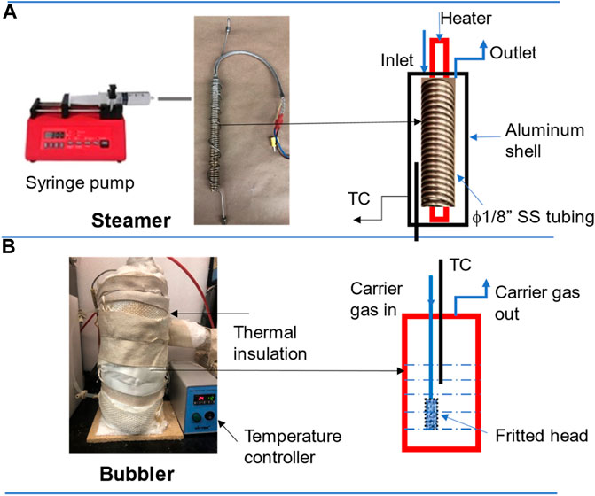
FIGURE 1. System setup of (A) steamer and (B) bubbler.
For the bubbler system, Figure 1B, it consists of a cylindrical aluminum tank in diameter of 3″ and height of 9″ wound by a heating tape (Tubing Heaters, McMaster-Carr), and a thick layer of ceramic fiber thermal insulation. The temperature of the bubbler is provided by the heating tape and controlled by a temperature controller (TC-508, VivTek Instruments). The carrier gas is led through a tube with a fritted end (a metal sponge) into the bubbler set at a desirable temperature and expected to be saturated with the amount of steam determined by the bubbler temperature. Table 1 lists some typical vapor pressures of water vs. temperatures. To study the effect of the bubble volume and fritted bubble head on the steam concentration, we made two bubblers: one with a volume of 1.25 L without the fritted end and another one with a volume of 3.0 L with the fritted end, for comparison.
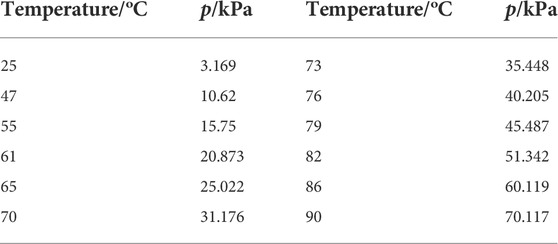
TABLE 1. Typical vapor pressure of water versus temperature (Lide, 2004).
Steam content and fuel cell measurements
The steamer and the bubbler were evaluated by a mass spectrometer (MS, Pfeiffer Omnistar 100), see Figure 2. The argon with a flow rate of 60 ml/min was used as the carrier gas for the measurement and was controlled by a mass flow controller (Alicat Scientific MFC Series). For the steamer, the generated steam was mixed with the carrier gas in a buffer vessel (200 ml, maintained at 200°C) through a “T” connector, where the steam content was controlled by the feeding rate of the syringe pump. For the bubbler, the carrier gas was fed directly into the water tank and the steam content was controlled by the bubbler temperature. The mixed gas was also led into a buffer vessel (1 L volume) for a better mixing before measurement. In all the measurements, the gas pipelines after the steamer/bubbler were made of stainless-steel tubing and maintained at 120°C all the time using the heating tape and ceramic fiber thermal insulation.
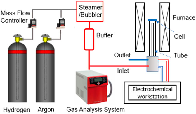
FIGURE 2. System setup for steam content and fuel cell measurement.
To independently verify the steam content measured by the MS, we also used a SOC to measure open circuit voltage (OCV), by which it was compared with the theoretical Nernst potential using H2/H2O ratio measured from the MS.
The SOC used for this study is consisted of a Ni/ScSZ (Sc-stabilized ZrO2) hydrogen electrode (HE)-supported ScSZ electrolyte cell with a GDC (Gd0.1Ce0.9O2) barrier layer and SrCo0.9Ta0.1O3-δ (SCT) oxygen electrode (OE). The overall testing system is shown in Figure 2. Silver wire/mesh together with gold paste were used as the current collector for OE, and Pt wire/Ni mesh with NiO paste was used as the current collector for HE. The cell was first glass sealed to an alumina tube and then heated to 700°C. The HE was first reduced by a 3% H2O-H2 at a flow rate of 50 ml min−1. The OCV of the cell was then measured at the same H2 flow rate but with different H2O contents: 3, 10, 20, 30, 40 and 50% H2O; the latter steam contents were created by either syringe-pump’s push rate in the steamer design or tank temperature of the bubbler design. At each steam content, OCV was measured continuously for 24-hour to check the stability of the steam supply. We have also measured the short-term electrolysis stability of the cell under 40%H2O-H2 using an electrochemical workstation (Solartron 1470E/FRA1255 Multi-Channel System).
Results and discussion
Comparison of steam contents by different steam generating devices
We first measured and compared the steam contents vs. device temperature for in-house steamer and Bubbler-1.25 L with an inlet gas tubing without fritted end; Figure 3 shows the results. For the steamer, oscillations occurred throughout the measurements at all H2O contents studied. We believe that it was due to the noncontinuous (stepwise) water feed by the syringe pump, particularly at low feed rate (low steam content). This explanation is supported by the fact that at a higher steam content (higher feed rate), the oscillations become less pronounced. Therefore, it is reasonable to predict that a better precision pump will produce more stable steam flow. Nevertheless, the average steam content for the steam seems to match with the desired value. On the other hand, a longer tube may also help provide steam stability. For Bubbler-1.25 L without inlet gas tubing fritted head, the steam content is stable during the test and no fluctuation was observed. However, roughly 5∼8% lower steam content than the set values is consistently observed. We believe this is likely due to the insufficient mixing of carrier gas and the steam caused by un-fritted inlet gas tubing head.
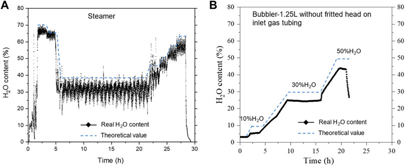
FIGURE 3. Comparison of steam contents from the homemade (A) steamer and (B) bubbler. Carrier gas flow rate: 60 sccm Ar.
Based on the above observation, we then changed the bubbler by increasing the total volume of the bubble from 1.25 to 3.0 L and added a fritted head to the inlet gas tubing. The testing results are shown in Figure 4. It is clear that the steam content is stable at all levels during the test; no sign of oscillations is seen. Moreover, the difference of H2O content between the set and measured values is within 0∼2%, demonstrating the improvement by the change of bubbler volume and inlet tubing. On the other hand, it is found that the steam content tends to drift with time, particularly at higher steam contents. This can be attributed to the partial steam condensation somewhere such as dead corners inside the bubbler as well as gradually lowered water level inside the bubbler. Thus, a larger volume is always preferrable for the bubbler to operate longer time without interruption such as water refill. In addition, the steam content variations at each temperature transition are likely caused by the bubbler temperature variations, which can be mitigated by re-tuning the temperature controller.
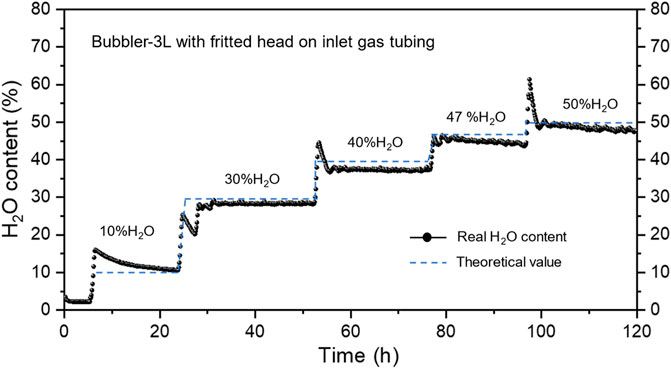
FIGURE 4. Steam content at different temperatures of a 3 L bubbler with fritted head of gas inlet tubing. Carrier gas flow rate: 60 sccm Ar.
Tesing bubbler performance in a solid oxide cell
To further verify the accuracy of the steam content generated by the 3.0 L bubbler, we used a solid oxide cell and measured its OCV as a function of H2/H2O ratio. From the measured steam contents, we first used Nernst equation to calculate the theoretical OCV; the comparison between the measured and calculated ones is shown in Figure 5. It is evident that the two data sets are reasonably close. Alternately, we also used the measured OCV to back calculate the steam content. Figure 5 again shows excellent agreement between the two. We, therefore, conclude that the bubbler is suited for providing accurate steam content for laboratory-scale solid oxide cell testing.
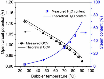
FIGURE 5. Comparison of OCV and steam content between measured and calculated values.
To demonstrate the steam stability in real cells, we tested SOFC operation at a low steam content for 50 h and SOEC operation at a high steam content for 264 h at 700°C; the results are shown in Figure 6. Evidently, there is no oscillation in either case, further proving the suitability of the bubbler we have designed for the laboratory-scale testing.
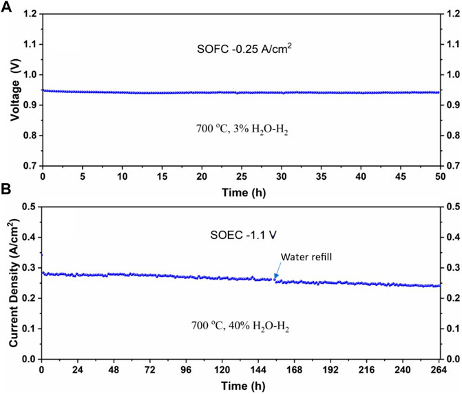
FIGURE 6. The stability of the cell under (A) low-steam SOFC and (B) high-steam SOEC modes at 700°C.
Throughout this study, we have gained some experience on designing and testing bubblers and steamers. Here we would like to share our candidate views on how to correct common abnormalities of steam generators; they are summarized in Table 2.
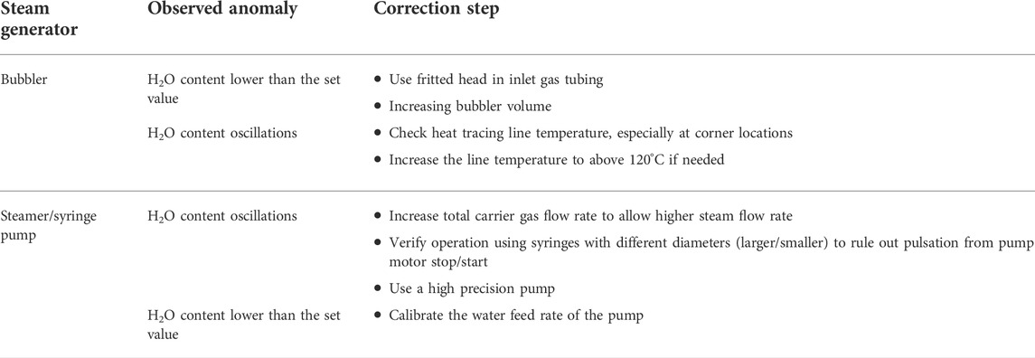
TABLE 2. Steam generators anomalies and corresponding correction actions.
Conclusion
In summary, we have demonstrated in this study that bubbler can provide a more stable steam supply than steamer at low steam flow rates, exhibiting less oscillations and accurate steam content up to 50% H2O. The main reason for the unstable steam generation by the steamer is likely due to the noncontinuous or stepwise water feed by the syringe pump, particularly at low water feed rates. At higher steam concentrations (or water feed rates), particularly at >60% H2O, where the accuracy of water feed of the pump is improved, steamer design may be better suited than bubbler. However, the energy consumption of steamers might be higher than bubblers since the former requires more energy to produce superheated steam (e.g., >150°C) than heating bubbler at less than 100°C. We also recommend the use of fritted inlet gas tubing to maximize the steam saturation of the carrier gas and larger volume to avoid interruptions by the frequent water refilling. Overall, bubbler is a better choice for laboratory-scale SOEC testing when low steam flow rates are encountered.
Data availability statement
The raw data supporting the conclusion of this article will be made available by the authors, without undue reservation.
Author contributions
YZ: Conducting experiments NX: Steamer setup QT: MS setup WG: design and results discussion KH: Supervision and manuscript writing.
Acknowledgments
This material is based upon work supported by the U.S. Department of Energy’s Office of Energy Efficiency and Renewable Energy (EERE) under the Fuel Cell Technologies Office (FCTO) under Award Number DE-EE-0008842. We would also like to thank National Science Foundation for the financial support under award number 1801284.
Conflict of interest
The authors declare that the research was conducted in the absence of any commercial or financial relationships that could be construed as a potential conflict of interest.
Publisher’s note
All claims expressed in this article are solely those of the authors and do not necessarily represent those of their affiliated organizations, or those of the publisher, the editors and the reviewers. Any product that may be evaluated in this article, or claim that may be made by its manufacturer, is not guaranteed or endorsed by the publisher.
References
Alabbadi, S. A. (2012). Hydrogen oxygen steam generator integrating with renewable energy resource for electricity generation. Energy Procedia 29, 12–20. doi:10.1016/j.egypro.2012.09.003
Buttler, A., and Spliethoff, H. (2018). Current status of water electrolysis for energy storage, grid balancing and sector coupling via power-to-gas and power-to-liquids: A review. Renew. Sustain. Energy Rev. 82, 2440–2454. doi:10.1016/j.rser.2017.09.003
Carmo, M., Fritz, D. L., Mergel, J., and Stolten, D. (2013). A comprehensive review on PEM water electrolysis. Int. J. hydrogen energy 38, 4901–4934. doi:10.1016/j.ijhydene.2013.01.151
Fujiwara, S., Kasai, S., Yamauchi, H., Yamada, K., Makino, S., Matsunaga, K., et al. (2008). Hydrogen production by high temperature electrolysis with nuclear reactor. Prog. Nucl. Energy 50, 422–426. doi:10.1016/j.pnucene.2007.11.025
Glenk, G., and Reichelstein, S. (2019). Economics of converting renewable power to hydrogen. Nat. Energy 4, 216–222. doi:10.1038/s41560-019-0326-1
Hauch, A., Jensen, S., Menon, M., and Mogensen, M. (2005). “Stability of solid oxide electrolyser cells,” in Risø international energy conference, 23–25.
Hauch, A., Küngas, R., Blennow, P., Hansen, A. B., Hansen, J. B., Mathiesen, B. V., et al. (2020). Recent advances in solid oxide cell technology for electrolysis. Science 370, eaba6118. doi:10.1126/science.aba6118
Hochmuth, F. W. (1978). Burning hydrogen and oxygen to superheat steam. Hudson, Canada: Google Patents.
Kim-Lohsoontorn, P., and Bae, J. (2011). Electrochemical performance of solid oxide electrolysis cell electrodes under high-temperature coelectrolysis of steam and carbon dioxide. J. Power Sources 196, 7161–7168. doi:10.1016/j.jpowsour.2010.09.018
O’Brien, J. E., Stoots, C. M., Herring, J. S., and Hartvigsen, J. J. (2007). Performance of planar high-temperature electrolysis stacks for hydrogen production from nuclear energy. Nucl. Technol. 158, 118–131. doi:10.13182/nt07-a3830
Schefold, J., Brisse, A., and Poepke, H. (2017). 23, 000 h steam electrolysis with an electrolyte supported solid oxide cell. Int. J. Hydrogen Energy 42, 13415–13426. doi:10.1016/j.ijhydene.2017.01.072
Shen, F., Welander, M. M., and Tucker, M. C. (2022). Metal-supported solid oxide electrolysis cell test standard operating procedure. Front. Energy Res. 10, 500. doi:10.3389/fenrg.2022.817981
Staffell, I., Scamman, D., Abad, A. V., Balcombe, P., Dodds, P. E., Ekins, P., et al. (2019). The role of hydrogen and fuel cells in the global energy system. Energy Environ. Sci. 12, 463–491. doi:10.1039/c8ee01157e
Vincent, I., and Bessarabov, D. (2018). Low cost hydrogen production by anion exchange membrane electrolysis: A review. Renew. Sustain. Energy Rev. 81, 1690–1704. doi:10.1016/j.rser.2017.05.258
Yamada, K., Makino, S., Ono, K., Matsunaga, K., Yoshino, M., Ogawa, T., et al. (2006). High temperature electrolysis for hydrogen production using solid oxide electrolyte tubular cells assembly unit. San Francisco, CA: AIChE Annual Meeting.
Zeng, K., and Zhang, D. (2010). Recent progress in alkaline water electrolysis for hydrogen production and applications. Prog. Energy Combust. Sci. 36, 307–326. doi:10.1016/j.pecs.2009.11.002
Zhang, X., O'Brien, J. E., O'Brien, R. C., Hartvigsen, J. J., Tao, G., and Housley, G. K. (2013). Improved durability of SOEC stacks for high temperature electrolysis. Int. J. Hydrogen Energy 38, 20–28. doi:10.1016/j.ijhydene.2012.09.176
Keywords: water feed rate, fritted head, bubbler volume, steam content, solid oxide electrolytic cell
Citation: Zhang Y, Xu N, Tang Q, Gibbons W and Huang K (2022) Evaluation of steam supply performance: Steamer vs. bubbler. Front. Energy Res. 10:963777. doi: 10.3389/fenrg.2022.963777
Received: 07 June 2022; Accepted: 28 July 2022;
Published: 02 September 2022.
Edited by:
Roel Van de Krol, Helmholtz Association of German Research Centers (HZ), GermanyReviewed by:
Bin Chen, Shenzhen University, ChinaFaran Razi, University of British Columbia—Okanagan Campus, Canada
Copyright © 2022 Zhang, Xu, Tang, Gibbons and Huang. This is an open-access article distributed under the terms of the Creative Commons Attribution License (CC BY). The use, distribution or reproduction in other forums is permitted, provided the original author(s) and the copyright owner(s) are credited and that the original publication in this journal is cited, in accordance with accepted academic practice. No use, distribution or reproduction is permitted which does not comply with these terms.
*Correspondence: Kevin Huang, SFVBTkc0NkBjZWMuc2MuZWR1