Abstract
State of health (SoH) imbalance causes capacity waste and cycle life reduction of the battery-based energy storage systems (BESS), which demands SoH balancing control of the parallel-connected packs and the series-connected cells of the BESS. This study proposed a multi-layer SoH balancing control to extend the cycle life of the BESS. For the series-connected battery cells, active equalization circuits based on the fly-back converter are used to exchange energy between cells and control the depth of discharge (DoD) of cells to achieve the SoH balance. For the parallel-connected packs, SoH is equalized by distributing the output power based on the SoH balancing principle and the minimum power distribution constraints of packs caused by the bidirectional balancing current among the series-connected cells are considered. Because the proposed method achieves the SoH balancing by utilizing the active equalization circuits to transfer the energy between the cells with different SoH, it can achieve higher capacity and energy utilization efficiency and lower heat release compared with the passive equalization typology that dissipates the energy. The effectiveness of the proposed method is verified by a case study based on a 3-packs-15-cells BESS. Simulation results show that this method can prolong the cycle life of BESS by about 52.9% compared with the active SoC balancing method using the same fly-back converter and 18.3% with a passive multi-layer SoH balancing method, respectively.
1 Introduction
With lithium-ion batteries being used extensively in both electric vehicles (EVs) and battery-based energy storage systems (BESS), cascade utilization of batteries is proposed to reduce cost and increase the capacity utilization of batteries. As the widespread application of EVs and BESS has brought huge requirements for lithium-ion batteries, cascade utilization of batteries is proposed to decrease carbon emission, reduce cost, and increase the capacity utilization of batteries. As the popular battery application, the EVs are recommended to retire the battery pack when its state of health (SoH) is reduced to 80% by manufacturers (Neubauer and Pesaran, 2011) to guarantee performance and adequate mileage. BESS for frequency regulation application also require high SoH of batteries because of the frequent and deep charge/discharge cycles (Zhang et al., 2020), so the batteries will be replaced when their SoH is even relatively healthy. However, the retired batteries from these applications remain sufficient capacity for the less-demanding energy storage service (Mukherjee and Strickland, 2015), such as the load-shifting BESS or the energy arbitrage BESS. The recycling of batteries is regarded as the second life of the battery and beneficial to the investors (Olsson et al., 2018).
Both the state of health (SoH) and the state of charge (SoC) of batteries in BESS should be considered and measured during the batteries management (Pattipati et al., 2011; Yang et al., 2021). The SoC regulation, which aims to keep the SoC of all batteries consistent, is applied for the short-term operation to fulfill the maximum energy release and prevent the overcharge/overdischarge condition of each battery cell during the process (Dogger et al., 2011; Lu et al., 2014). Meanwhile, the SoH regulation is appropriate for long-term operation to prolong the cycle life of the BESS (Tran and Khambadkone, 2013), which is expected to attain similar SoH values for all batteries. Therefore, it can avoid capacity waste when the minority battery cells or packs reach the lowest SoH level but others can still offer normal energy throughput. The SoH imbalance is inevitable during the reassembly due to the retired batteries come from different operating conditions with different initial SoH (Chowdhury et al., 2019).
In practice, BESS usually consist of parallel-connected battery packs, while the packs are composed of series-connected battery cells. Thus, regulation techniques have to consider parallel and series layers as their operation conditions are disparate. For battery packs in parallel, droop control is quite common in SoC regulation control by modifying a suitable droop coefficient for the different charge/discharge currents to accomplish the SoC balance (Belal et al., 2019; Bi et al., 2020). Huang et al. (2015) presented an energy-sharing SoC balancing control scheme based on a distributed BESS architecture. Cao and Abu Qahouq (2021) proposed a hierarchical SoC balancing control method, which can control the SoC at both the cell level and the module level while simultaneously maintaining bus voltage regulation at the battery system or pack output. For battery cells in series, the equalization circuit is regarded as the most straightforward solution for SoC balancing as it can change the output current of each series-connected cell. The passive or active equalization circuits are usually used to balance the SoC of series-connected battery cells in a pack. They are also referred to as dissipation and non-dissipation equalization circuits, respectively. Cao et al. (2008); Daowd et al. (2011) reviewed and compared several state-of-the-art equalization topologies to show the characteristics of different equalization circuits. Koseoglou et al. (2020) proposed a high-effective cell equalization method using MOSFET and a shunt resistor to balance the cells. The dissipation equalization topology is applied in this method. For non-dissipation topologies, Azad et al. (2020) presented a novel active balancing topology using a single LC series resonant circuit and a single capacitor. An optimal cell-to-cell balancing topology is proposed to improve the balancing speed of equalization circuits (Ouyang et al., 2018). The fly-back converter topology has higher balancing efficiency compared with the inductor or capacitor and a more straightforward structure than those novel improving topologies (Lee et al., 2017). Overall, most SoC balancing methods aim to realize the same depth of discharge (DoD) for cells by controlling the output of each battery to maintain the SoC balance. In contrast, SoH balancing method requires a different DoD for each battery, which leads to disparate capacity degradation for batteries with different initial SoH and finally balances the SoH of all batteries. Because of the same control principle, the SoC balancing methods can be referenced for SoH balancing control.
Several works have discussed BESS’s cycle life degradation during operation, either among cells in battery packs or battery packs in the system. A pack-level SoH balancing control method applied to the modular multilevel converter-based battery energy storage system (MMC-BESS) is proposed by Li et al. (2018) as controlling the DC circulating current and fundamental frequency circulating current to realize the power distribution between each sub-module. Chowdhury et al. (2019) presented an integrated SoH balancing method for lithium-ion batteries with a simplified topology connected through a DC/DC converter. Output distribution is a common method to balance the SoH of parallel-connected batteries, which can be implemented by offering different currents for each battery. However, it is not applicable for battery cells in series as all cells have the same series current. The SoH imbalance among series-connected cells in the battery pack also leads to the low equivalent SoH of the battery pack, which is even lower than the SoH of the poorest cell in that pack. Therefore, equalization circuit techniques are the appropriate method to balance the SoH of cells in series. For series-connected cells, Ma et al. (2018) presented an enhanced SoH balancing control by using passive equalization topology based on shunt resistors to achieve the SoH balancing for cells in MMC-BESS. This method can increase the equivalent SoH of battery packs to the SoH of the poorest cell in that battery pack due to utilizing the passive equalization technique. In addition, Probstl et al. (2018) presented an SoH-aware active cell balancing strategy using an inductor-based active cell balancing architecture to transfer the energy from cells with higher SoH to the low SoH neighbors. This method can increase the equivalent SoH of the battery pack to the average SoH of all cells in that pack. However, the SoH balancing efficiency is not high because the energy transfer efficiency of the inductor is limited. Ziegler et al. (2018) believed that active equalization has no negative ageing on cells and can accomplish a longer cycle time compared with passive equalization. A long-term testing for all single cells in the system is carried out to verify his viewpoint. Furthermore, Bouchhima et al. (2018) proposed a novel multi-cell lithium-ion storage system called a ’self-reconfigurable battery’ to enhance the lifetime of BESS.
However, few studies have investigated the SoH balancing for the parallel layer and series layer simultaneously in the BESS. For BESS, the SoH balancing is not a simple combination of SoH balancing in series and SoH balancing in parallel as the status of each battery pack and cell during the operation is coupled dynamically and needs coordinated control.
Khasawneh and Illindala (2014) presented three possible directions to balance the cycle life of all batteries in the microgrid.
Ma et al. (2020) presented a multi-layer SoH equalization scheme that can balance the SoH for all cells in BESS. The parallel-connected battery packs are equalized based on the SoH balancing scheme (
Ma et al., 2018). The passive equalization circuit with the shunt resistor is applied to balance each cell among battery packs by dissipating the redundant energy from the cells with higher SoH. This scheme can equalize all cells in BESS. It also increases the equivalent SoH of each battery pack to the SoH value of the poorest cell among that pack, as the equivalent SoH of a battery pack is normally lower than this value without balancing methods. In this study, a modified multi-layer SoH balancing control is proposed for BESS which is already installed or planning to install the active equalization circuits for battery management. The principle and characteristics of passive and active equalization topologies have been analyzed. Compared with the passive multi-layer SoH balancing method mentioned in the study by
Ma et al. (2020), the proposed method considered the constraints brought by the bidirectional balancing current for cells in series. The determination of all balancing parameters is modified to appropriate the active balancing among cells. The power distribution between parallel-connected packs is also modified by considering the constraints obtained by the balancing parameters in the series layer. The proposed method has been verified by simulation in a 3-packs-15-cells BESS model. The traditional SoC equalization methods and a multi-layer SoH equalization scheme (
Ma et al., 2020) have been carried out under the same conditions to compare the result. The proposed method can balance the SoH of all cells in BESS and further extend the cycle life of the system. The main contributions can be summarized as follows:
• This study proposes a multi-layer SoH balancing control method for BESS to extend the cycle life based on the active equalization circuits
• The proposed method utilizes the fly-back converter equalizer to achieve less power dissipation with higher balancing efficiency during the balancing control process
• The control scheme considers the bidirectional balancing current in the active equalization circuits and proposes a determination method for balancing current in the cell equalizer
• Compared with the traditional active SoC equalization method and the multi-layer SoH equalization scheme with passive equalization circuits, the proposed method can improve the cycle life by 52.9% and 18.3%, respectively
This article has been organized as follows: Section 2 introduces the imbalance among batteries and the application of battery equalization topologies for SoH balancing control. The control structure, the proposed control method, and the detailed formula derivation are explained in Section 3. Based on a 3-packs-15-cells BESS model in MATLAB/Simulink, Section 4 demonstrates the simulation result of the proposed balancing method. A comparison is also carried out by comparing the result of several state-of-the-art balancing methods. At last, the result of this study is concluded and future research is discussed in Section 5.
2 Battery imbalance and equalization
2.1 SoH modeling
In general, the SoH is usually defined as the capacity degradation of batteries, which is interpreted as the maximum available capacity to its initial nominal capacity during the study of energy storage system control. The definition of SoH in terms of capacity degradation is expressed as follows:where Qmax and Qrated are the available maximum capacity and the nominal capacity, respectively.
Full charge capacity estimation (Shahriari and Farrokhi, 2013) is the common method to estimate the SoH of batteries but requires a long-term experiment. To find out an easily accessed measurement variable for the SoH estimation, Dogger et al. (2011) studied the relationship between battery capacity degradation and life cycles and identified it as a linearized or quasi-linearized curve, which provides the possibility to estimate the SoH by the life cycle (Tran and Khambadkone, 2013). Meanwhile, the relationship between the life cycle and DoD has been carried out by eliminating the temperature difference during the battery ageing process (Dallinger, 2012). Although the battery ageing progress is a complex process that can be affected by operating temperature, current rate, DoD, or their combination (Hu et al., 2016), the temperature difference could be eliminated because the commercial or industrial BESS general has installed heat dissipation apparatus to avoid over-heat or high-temperature difference. Thus, the relationship between SoH and DoD can be obtained aswhere Cleft is the life cycles left before the SoH drop to 0, Cltotal is the total life cycles, Cacu is the accumulated life cycles, and SoH(0) is the initial SoH value. The a and b are parameters obtained from the fitting curve of the battery’s ageing (Li et al., 2018). Cleft, Cltotal, and Cacu are all obtained under the same DoD, which stands for the percentage of the practical released amount of charge compared with total capacity (Shahriari and Farrokhi, 2013) and can be defined by the coulomb counting method, similar to the SoC, as follows (Meissner and Richter, 2003):where Qrelease and id represent the released energy of the battery and the discharge current during the operation, respectively.
According to the above mentioned Eqs 2, 3, it can be assumed that the SoH is related to the discharge current id, making the SoH balancing control for BESS possible.
2.2 Battery imbalance
Generally, the BESS consists of several high voltage battery packs connected in parallel to attain a large capacity. The battery cells are series-connected to constitute a battery pack with high voltage, as shown in Figure 1. However, most battery balancing control methods usually regard the battery pack of series-connected cells as a single “high voltage battery” (Li et al., 2018) because the operation of cells in series cannot be controlled separately with the traditional structure, which means the working states of every single cell are ignored.
FIGURE 1

Simple BESS structure.
The ideal operation condition for series-connected cells is shown in Figure 2A, where all cells can reach the same charging/discharging status simultaneously. The length of the battery represents the available capacity and the colored rectangle indicates the remaining power.
FIGURE 2

Illustration of the performance of series-connected cells in battery pack under (A) ideal status and (B) real status.
However, due to the inevitable error during the battery manufacturing process, such as the different initial capacity of internal resistance, each cell’s charging/discharging status (SoC/DoD) is usually different. Different discharging statuses (DoD) will lead to different ageing speeds based on the Eq. 2. Even for the brand new batteries, the imbalance will become pronounced in long-term operation, and the condition of the batteries retired from EVs can be worse. Figure 2B shows one of the worst situations where all cells have different SoH and unequal initial SoC. For all cells in series, the charging process will be stopped when cell-1 is fully charged. The discharging process will only continue before cell-3 is completely discharged because the battery management system (BMS) will avoid the overcharge/overdischarge condition for all cells. This situation will cause capacity and energy waste during each operation and the further widening of imbalance as the capacity of cells with lower SoH will degrade faster and the ageing process of cells with higher SoH will become slower (Cao et al., 2008).
2.3 Equalization circuits for battery in series
Thus, the straightforward solution is to use the traditional cell SoC equalization methods with balancing circuits, such as passive or active balancing circuits (Cao et al., 2008; Daowd et al., 2011), to enlarge the available capacity. Figure 3 demonstrates two conventional equalization circuits.
FIGURE 3

Two typical cell equalization topologies by using (A) shunt resistor for passive equalization and (B) fly-back converter for active equalization.
Figure 3A shows the shunt resistor topology for the passive equalization, which balances the series-connected cells’ energy by dissipating the redundant energy through the resistor. So, the passive equalization methods are also referred to as the dissipation equalization methods. However, the active equalization circuits balance the series-connected cells by transferring the energy from the healthier cells to the poorer cells. Figure 3B demonstrates the typical fly-back converter topology for active equalization.
Based on the balancing circuits, the operation current for all cells in series can be controlled individually by offering a different balancing current ibal for each cell, shown in Figure 4. Because the current flow is in series is equal for each cell, the practical discharge current id,i for cell-i can be straightly modified by changing the balancing current ibal,i for cell-i, which means the balancing circuits can control the DoD/SoC of each cell in series according to Eqs 2, 3.
FIGURE 4

Principle of equalization circuits for cells in series.
The balancing performance of passive equalization circuits is illustrated in Figure 5A where the blue rectangle represents the remaining energy in the cells. The red rectangle expresses the power dissipated by the shunt resistor and the white rectangle referred to the effective output. Although this method can achieve similar depth of discharge (as A, B, and C) for each cell, the effective output or effective capacity of each cell can only reach the poorest cell’s value (shown as cell-3). The equivalent SoH of the battery pack equals the SoH of the poorest cell (cell-3) (Ma et al., 2020).
FIGURE 5
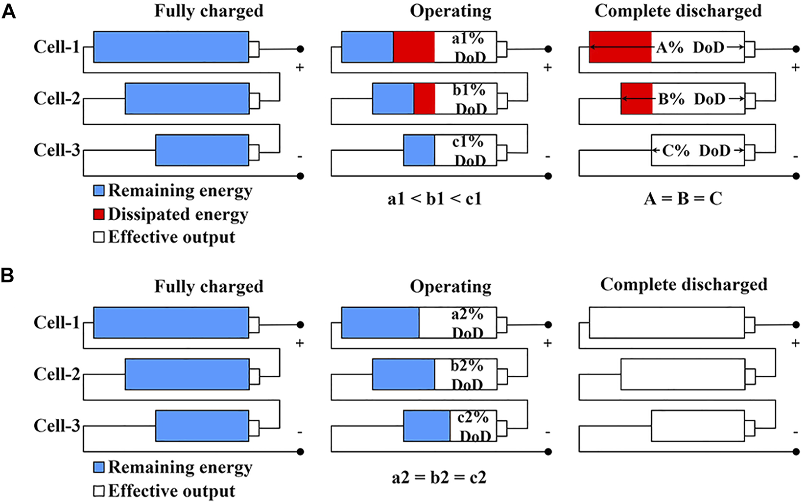
Illustration of the performance of series-connected cells in a battery pack with (A) passive balancing circuits and (B) active balancing circuits.
On the other hand, Figure 5B shows the operation performance of active equalization circuits. Because the poorer cell (cell-3) can receive additional energy transferred from the healthier cell (cell-1/cell-2), the SoC of each cell can be balanced (a2, b2, and c2 are equal) and the poorer cell can output less energy during the operation. The active equalization method can make full use of the capacity of each cell and the effective output of each cell can rise to the available maximum value itself. The equivalent SoH of the battery pack is equal to the average value of the SoH of all cells (Ma et al., 2020).
Hence, in theory, the equivalent SoH of the battery pack with different equalization circuits can be summarized as follows:
2.4 Application of the equalization circuit in SoH equalization
Because the equalization circuits can control the DoD of each cell in series individually, it is possible to realize the SoH equalization for cells by utilizing the relationship between SoH and DoD mentioned in the Eq. 2. Unlike the SoC balancing method, the SoH balancing method requires the DoD of each cell to be varied to achieve the different SoH decreases. Assuming two batteries (i and j) with different initial SoH, their instant SoH value can be addressed as
Setting the Cacu,i equal to the Cacu,j, the SoH value of two batteries can be balanced by offering different DoD.
Ma et al. (2020) have already proposed a multi-layer SoH balancing method applied for the BESS with the passive equalization circuits (shunt resistors topology). However, the BESS cycle life extending of passive equalization circuits is not as good as the active equalization circuits due to its dissipation characteristics. Using Figure 4 as the reference for current direction, during the discharge process, although the passive equalization circuits can boost the practical discharging current id for cells with higher SoH by increasing the balancing current ibal to achieve the SoH equalization, it cannot reduce the actual discharging current for cells with lower SoH because the balancing current cannot be negative, which means the lowest discharging current cannot be lower than the series current is. Because the poorest battery determines the retirement of BESS, the passive equalization can achieve the SoH balancing but hardly further extend the cycle life of the system.
On the other hand, active equalization circuits could overcome this issue as the balancing current of active equalization topologies is bidirectional, which means the ibal can be negative and the practical discharge current id for cells with lower SoH can be decreased towhere ibal,min is the maximum balancing current of the equalization circuits in the opposite direction. According to the Eqs 2, 3, a lower discharge current will lead to a slower ageing process, which reflects the ability of active equalization topologies for BESS cycle life extending.
For the multi-layer SoH balancing control scheme, active equalization circuits own the ability to balance the SoH of cells in BESS and satisfactory performance in BESS life extending. Although it is difficult to trade-off between the benefit of BESS life extension and the extra cost of active equalization circuits installation, it is still worthwhile to propose a modified multi-layer SoH balancing method for those BESS who have already installed or plan to install the active equalization circuits. Thus, the fly-back converter balancing circuits (shown in Figure 3B) are chosen as the cells’ equalization topology in this research.
3 Multi-layer SoH balancing control
3.1 BESS operation scheme
Based on the relationship between SoH and DoD and the characteristics of the cell equalization circuits, the modified multi-layer SoH balancing control method for BESS with active equalization circuits are proposed. The general BESS block structure with active equalization circuits is shown in Figure 6, where a 3-packs-15-cells BESS is applied as an example to briefly demonstrate the control structure and logic.
FIGURE 6
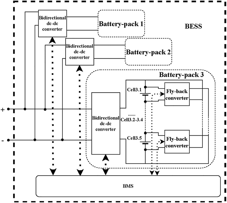
3-packs-15-cells BESS block structure with multi-layer SoH balancing control.
This BESS consists of three battery packs in parallel and each battery pack includes five cells connected in series. As the total power demand is confirmed, the BMS will first distribute the power output to three parallel-connected battery packs based on the equivalent SoH of each pack. After the reference output of each pack is distributed, the BMS will balance the cells among each battery pack using the secondary SoH balancing control method. The detailed control method and formula derivation will be introduced as follows.
The BESS should satisfy the following constraints during the operation to avoid dangerous conditions and significantly accelerated ageing.where DoD limitation DoDlimit is 0.8 and SoH retired level SoHretired is 0.4. The SoC operation range SoCmin and SoCmax are 0.1 and 0.9, respectively.
3.2 SoH balancing control for parallel-connected battery packs (pack level)
Different DoD could be simply achieved for parallel-connected battery packs by offering different reference power for each pack. According to the Eq. 5, once the DoD of the pack with the highest SoH value is set as the maximum DoD (0.8), the DoD for other packs could be easily calculated by determining the accumulated life cycle Cacu,pack for battery packs. The value of Cacu,pack should not be less than the minimum value, which can be calculated aswhere Cacu, min,pack is the minimum value of the accumulated life cycle to achieve the SoH balance for battery packs. SoHini,best and SoHini,worst are the SoH value of the battery pack with best condition and worst condition (highest SoH and lowest SoH), respectively. DoDmin,worst is the minimum DoD for battery pack with the lowest SoH value. Because the balancing current is bidirectional in the active equalization circuits, the DoDmin,worst should satisfy the following constraints to avoid circulating currents in packs.where ic, min,worst is the minimum practical charging current for cells in that battery pack, which has opposite direction with id, min,worst. Combining with Eq. 6, it can be obtained as the constraints for DoDmin,worst by regarding the series current is,worst as applied current iapp,worst, which can be calculated as follows:
Once the Cacu,pack is determined, the DoDpack of other battery packs can be obtained based on the Eq. 5, which is described as
For battery packs connected in parallel, SoH balancing control can be achieved by offering a different reference output to each battery pack. The normalized DoDs are proportional to the average output power of corresponding battery packs during each charging and discharging cycle. Li et al. (2018) has proposed a power distribution method appropriate for SoH balancing control of parallel-connected battery packs. According to the normalized DoDs, the output power per battery pack can be calculated aswhere Ppack,i is the power demand allocated to the ith battery pack and Ptotal is the total output power.
3.3 SoH balancing control for series-connected battery cells (cell level)
Once each battery pack’s power demand is determined, the applied current for each battery pack can be easily expressed aswhere and vpack represent the power reference of battery packs calculated by the SoH balancing among battery packs and the pack’s real-time terminal voltage, respectively. After the applied current for each battery pack is calculated, the next step is the SoH balancing control among cells in the relevant battery pack.
Generally, both the passive and active equalization circuits can be utilized to realize the SoH balance among cells by properly controlling their DoD. In brief, different DoDs of cells could cause different degradative rates. Thus, for example, the SoH of all cells in a series can be equalized by offering larger DoDs to cells with higher SoHs and smaller DoDs to cells with lower SoHs.
Choosing the cells in ith pack as an example, setting the DoD value of the healthiest cell as the maximum value DoDi, max (0.8), the normalized DoD of other cells can be obtained using a similar calculation like the Eq. 11. For the jth cell in ith pack, the DoDi,j can be calculated as follows:
However, it is quite different between cells’ connection in a pack and packs’ connection in the BESS. Although the minimum accumulated cycle life Cacu,min,i can be calculated by the similar equation as in the study by Dogger et al. (2011), the minimum DoD (DoDmin,worst,i) for the cell in pack-i with the lowest SoH value should be determined by the different equation.
Setting the maximum available DoD (as DoDmax,i) in pack-i as the DoD of the healthiest cell. The balancing current Ibal is set to the maximum value with the same direction of applied charging and discharging currents (iapp,i) for the healthiest cell and with the opposite direction of applied charging and discharging current for the poorest cell within balancing current limitation (Ibal,max or Ibal,min) to get the smallest DoD for the poorest cell (DoDworst,i). The direction of current refers to Figure 3B. According to the same charging/discharging time, Eqs 15, 16 can be obtained as follows:where Qmax,best,i and Qmax,worst,i are the capacity of the healthiest cells and the poorest cells in pack-i, respectively, which are already calculated by the SoH estimation process. ic,i and id,i are the applied charging and discharging currents (iapp,i) in the series branch of the ith battery pack, calculated by Huang et al. (2015). DoDworst,c,i and DoDworst,d,i refer to the DoD of the poorest cell in pack-i when charging/discharging obtained by solving the Eqs 15, 16. The DoDmin,worst,i is addressed as the larger one to maintain the same DoD during charging and discharging operation. Then the minimum accumulated cycle life Cacu,min,i can be obtained by Eq. 8. The setting value of Cacu,i should be equal to or larger than Cacu,min,i.
Next, the balancing current for each cell can be calculated for charging and discharging, respectively. During the charging process, fly-back converters separate the charging current (Ibal,c > 0) of poor cells to lower their charging power and send back extra charging current (Ibal,c < 0) to healthier cells to make them charged deeper. The balancing current of the healthiest cell is set to the maximum value with the same direction of applied charging current as Ibal,min to achieve the deepest charging. Replacing the charging parameters of the cell with the lowest SoH value to the parameters of the jth cell in pack-i in the Eq. 15, the reference balancing current of the jth cell in pack-i during the charging process is obtained as follows:
Similarly, when discharging, the cells with the smaller SoH will receive extra power (Ibal,d < 0) from the fly-back converter to slow down its discharging and the cells with higher SoH will be required to send extra power (Ibal,d > 0) to the fly-back converter to achieve deeper discharge. The balancing current of the poorest cell is set to the maximum value with the opposite direction of applied discharging current as Ibal,min to accomplish the most shallow discharge. Replacing the discharging parameters of the cell with the highest SoH value to the parameters of the jth cell in pack-i in the Eq. 16, so the reference balancing current of the jth cell in pack-i during discharging process can be calculated as follows:
Generally, the efficiency of the typical fly-back converter is 0.80–0.9. A research (Boeke, 2007) has pointed out that the efficiency of the fly-back converter can achieve 96% during the experimental test. Although many advanced topologies have been proposed in recent research with higher efficiency, the proposed method is appropriate for these topologies if the energy transfer principle is similar. Considering that the selected fly-back converter topology is just an example of the active balancing circuits, the energy transfer efficiency is set a little bit higher, as ηp = 0.95 and ηs = 0.9, to reflect the energy loss through the active balancing circuits during the operation. ηp and ηs represent the energy transfer efficiency of the equalization circuit on the primary and secondary sides. Based on the efficiency, the effective charging/discharging current of the cells in series could be obtained as follows:where Id,i,j is the effective discharging current of the jth cell in pack-i. Ibal,d,i is the total equivalent discharging balancing current on the secondary side of the active equalization circuit, which can be calculated as follows:
is the ratio of the transformer in the fly-back converter. Ibal,d,i,pos and Ibal,d,i,neg reflect the positive and negative balancing current during the discharging process. The direction of the balancing current refers to Figure 4.
The effective charging current can be calculated by a similar method, as follows:where Ic,i,j is the effective charging current of the jth cell in pack-i. Ibal,c,i is the total equivalent charging balancing current on the secondary side of the fly-back converter, which can be calculated as
I bal,c,i,pos and Ibal,c,i,neg reflect the positive and negative balancing current during the charging process. The direction is the same as the discharging current.
Because of the inevitable power loss during the power transmission, all cells in a pack will be charged less and discharged more than the reference value. Therefore, the power supplement is required during the charging process to avoid out-of-limit SoC value caused by mismatched charging/discharging. The supplement charging current Ic,i, sup can be obtained as follows:
It should be noticed that the “cell” in this section does not necessarily represent every battery cells in a BESS. Instead, it means the series-connected minimum controllable unit in the system as some systems are not able to control every single cells but the series-connected packs.
3.4 Overall control structure
The overall control structure and logic are illustrated in Figure 7.
FIGURE 7
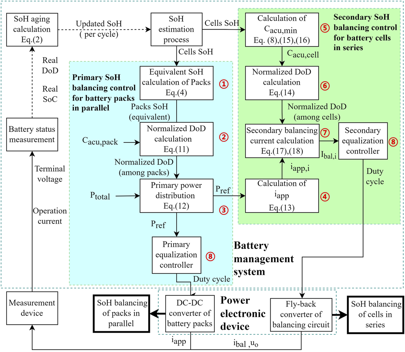
Overall control structure diagram of the multi-layer SoH balancing control with active equalization circuits.
From the figure, ① to ⑧ show the control logic and order of the multi-layer SoH balancing control method, which can be briefly summarized as follows. The SoH estimation process obtained the SoH of each cell in BESS at first; then,
① Based on the SoH of each cell in battery packs, the primary SoH balancing control will calculate the equivalent SoH of each pack according to the equalization circuits used in the BESS as Eq. 4
② The normalized DoD of each battery pack then be calculated due to the equivalent battery pack SoH and Cacu,pack as Eq. 11
③ According to the normalized DoD, the total power demand will be distributed to each battery pack, as Eq. 12.
To this step, the calculation of the primary SoH balancing control is finished. The secondary SoH balancing control then proceeds to refer to the reference power of each battery pack.
④ Based on the reference power distributed by primary SoH balancing control, the applied charging and discharging current iapp will be calculated at first as Eq. 13.
⑤ Different from primary balancing control, the Cacu,cell needs to be calculated due to the SoH of cells and equalization circuits, as Eqs 15, 16, 8.
⑥ Then the normalized DoD of each cell is calculated referring to the SoH of cells and the obtained Cacu,cell as Eq. 14.
⑦ Next, the balancing current of each cell can be calculated as Eqs 17, 18.
The final step ⑧ is to send the control signal from the controller to the power electronic device and realize the balancing control. During the operation, the measurement device collects the operation data from each power electronic device to monitor each battery cell’s terminal voltage and operating current. After each cycle, the information will be organized to calculate and update the SoH of each cell as an Eq. 2.
In practical applications, errors exist in SoH estimation and the accurate SoH values of cells are difficult to monitor during the online operation, which brings challenges for the balancing control. However, the proposed method only requires the accurate SoH value at the beginning before the first cycle and the end after the system reaches the retired level. For the first condition, offline SoH determination is not difficult and there are already many commercial solutions. For the second condition, the SoH determination is decided by the protection system, which means it will affect the total cycle time for all control methods. Because this error is inevitable and caused by the system, it can be ignored when comparing different control methods.
During the operation, the proposed method only requires the relative deviation of SoH between each cell in a pack to estimate whether the pack is balanced or not. Thus, instead of an accurate SoH value, an approximate value calculated by the available measurement will be applied to determine the status of the batteries. The calculation of the approximate SoH is shown follows:where SoHapp is the approximate SoH and Qrated is the nominal capacity. ΔQ and DoD are the released energy and the depth of discharge in the time duration. The status measurement device can obtain both these two values.
4 Simulation and comparison
4.1 Simulation condition
A simulation model of the 3-packs-15-cells BESS with the fly-back converter equalization circuits is built in MATLAB/Simulink. Due to the balancing current ratio (ratio of the equalizing current to the operating current) can effectively enhance the performance of balancing (Lou et al., 2017); a single battery cell (nominal voltage 3.7 V) is selected as the minimum unit in this simulation. The prototype of the fly-back converter equalization circuits is the same as Figure 3B and the parameters of BESS and equalization circuits are listed in Table 1. In addition, the BESS structure is shown in Figure 6 and the overall control structure is shown in Figure 7, which is applied in simulation.
TABLE 1
| Item | Value |
|---|---|
| Pack number | 3 |
| Amount of series-connected cells per pack | 5 |
| Battery cell type | Lithium-ion |
| Nominal capacity of cell | 12 Ah |
| Nominal voltage of cell | 3.7 V |
| Parameters of degradation, a, b | 694,0.795 |
| Power demand | 150 W |
| Maximum balancing current | 2A |
| Minimum balancing current | -2A |
| Ratio of transformer in fly-back converter | 1:5 |
| n p : ns | |
| Energy transfer efficiency ηp | 0.95 |
| Energy transfer efficiency ηs | 0.9 |
Simulation parameters.
In Simulink, the Lithium-ion batteries are simulated using the battery block from the library ElectronicDrive/ExtraSources. The initial SoH and initial SoC of each cell are set manually at the beginning of the simulation. They will automatically change after each charging/discharging cycle with equalization control during the simulation process. With the active equalization circuits, SoHpack can be promoted to the level of its average value of all cells in the pack. The power distribution and the equivalent SoH values for three battery packs are shown in Table 2.
TABLE 2
| Pack | 1 | 2 | 3 |
|---|---|---|---|
| SoH ini | 0.85 | 0.8 | 0.75 |
| Power distribution | 62.53 | 49.79 | 37.68 |
Equivalent initial SoH for battery packs with active balancing circuit.
The 3-packs-15-cells BESS is applied to supply 150 W power for 50 min. According to the Eqs 11, 12, the distributed output power of pack-3 can be calculated. For cells in pack-3, the parameter Cacu is calculated as 171 based on the Eqs 8, 13, 15, 16 with the setting simulation condition. The maximum DoD of the simulation is chosen as 80% to avoid overdischarge. Only the values of each cell in pack-3 are shown in Table 3. Thus, with the initial SoH shown in Table 3 and the chosen DoDmax as 80%, the DoD and balancing current of cells undercharging/discharging conditions in pack-3 during the first cycle can be calculated according to the SoH equalization Eqs 14, 17, 18, and listed in Table 3.
TABLE 3
| Cell | 1 | 2 | 3 | 4 | 5 |
|---|---|---|---|---|---|
| SoH ini | 0.85 | 0.80 | 0.75 | 0.70 | 0.65 |
| SoC ini | 0.9 | 0.9 | 0.9 | 0.9 | 0.9 |
| DoD | 0.80 | 0.6369 | 0.4821 | 0.3396 | 0.2037 |
| 1.80 | 0.51 | -0.56 | -1.42 | -2 | |
| -2 | -0.64 | 0.49 | 1.39 | 2 |
Initial states and SoH equalization parameters for each cell.
4.2 BESS cycle time comparison
During each discharging cycle, the total demanding power is 150 W with a time duration of 50 min. Then, all battery cells are recharged to the initial SoC levels (set as 0.9) and the number of the life cycle is accumulated. The SoH is estimated and recorded after each life cycle. Once the unbalance of SoH between cells reaches the acceptable value, the control strategy will transfer to SoC balancing control to maintain the acceptable SoH difference until the cell is retired. This principle is also appropriate for pack-level SoH balancing control.
According to the simulation result, the balancing performance of the active equalization circuit-based multi-layer SoH balancing control of cells in pack-3 is shown in Figure 8A and Figure 9B. All cells in BESS can operate 691 times before one of them attach the retiring level. Thus, the 3-packs-15-cells BESS are considered to cycle 691 times under the multi-layer active SoH balancing control.
FIGURE 8

Cell-level balancing performance of (A) proposed method, (B) passive SoC balancing control, (C) active SoC balancing control, (D) and SoH equalization control with passive balancing circuits.
FIGURE 9
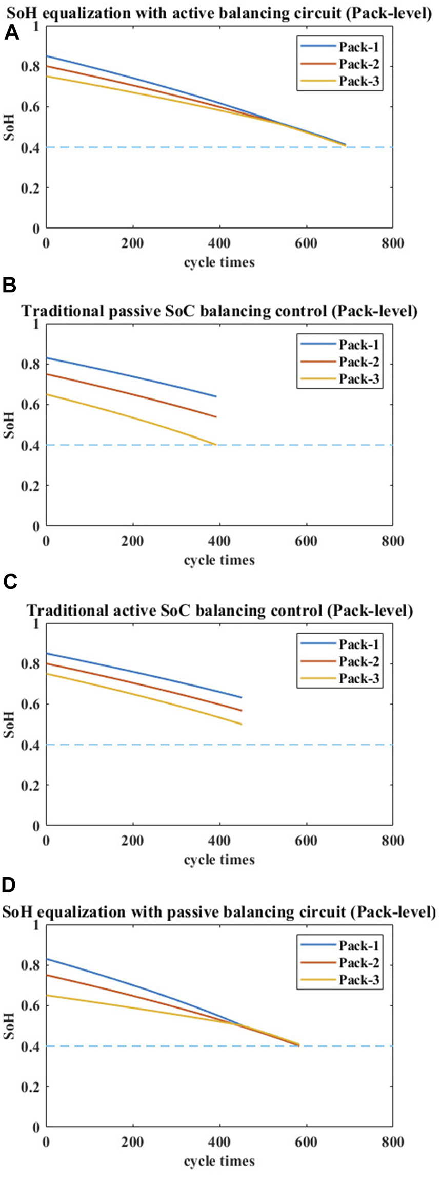
Pack-level balancing performance of (A) the proposed method, (B) passive SoC balancing control, (C) active SoC balancing control, and (D) SoH equalization control with passive balancing circuits.
As a comparison, Figures 8B, 9B, Figures 8C, 9C, and Figures 8D, 9D show the ageing phenomenon of packs in BESS and cells in pack-3 under passive SoC balancing control, active SoC balancing control, and multi-layer SoH equalization control with passive balancing circuits, respectively.
Although there are other SoH balancing methods, the multi-layer method has a better performance than those single-layer methods. Thus, only the performance of the multi-layer SoH balancing method is compared. The effective cycle times before BESS retired of these methods are 393, 452, and 584, respectively. Thus, the proposed multi-layer SoH balancing control with active equalization circuits can increase about 75.8, 52.9, and 18.3% life cycle compared with the three methods previously mentioned for the mentioned condition. The total energy stored and released of the BESS under different control methods has also been calculated as a quantitative reference for energy storage and supply. The comparison can also be observed in Table 4. Therefore, the proposed balancing method can well equalize the SoH of all cells and all packs and significantly prolong cycle times compared with the state-of-the-art battery balancing method.
TABLE 4
| Balancing method | Effective | Improvement of the | Total energy |
|---|---|---|---|
| cycle times | proposed method | stored and released | |
| Passive SoC balancing | 393 | +75.8% | 49.125 kWh |
| Active SoC balancing | 452 | +52.9% | 56.5 kWh |
| Multi-layer SoH equalization (passive equalization circuits) |
584 | +18.3% | 73.0 kWh |
| Proposed multi-layer SoH balancing (active equalization circuits) |
691 | - | 86.375 kWh |
Comparison of the previous methods and the proposed method.
4.3 SoC curve and other conditions
As the active multi-layer SoH balancing control method is used to replace the active SoC balancing method, while the cycle time of the BESS is extended, the SoC value of each cell should also satisfy the limitation of the SoC balancing method, as shown in the Eq. 7. The SoC curve of all cells in pack-3 was measured during the operation. Figure 10A shows the SoC variation during the whole operation. The SoC level of all cells is slowly decreased due to the error between the effective charging current and the effective discharging current. Thus, the SoC of all cells is charged to the initial level by applying an additional charging process when the cells are determined as ‘balanced’.
FIGURE 10
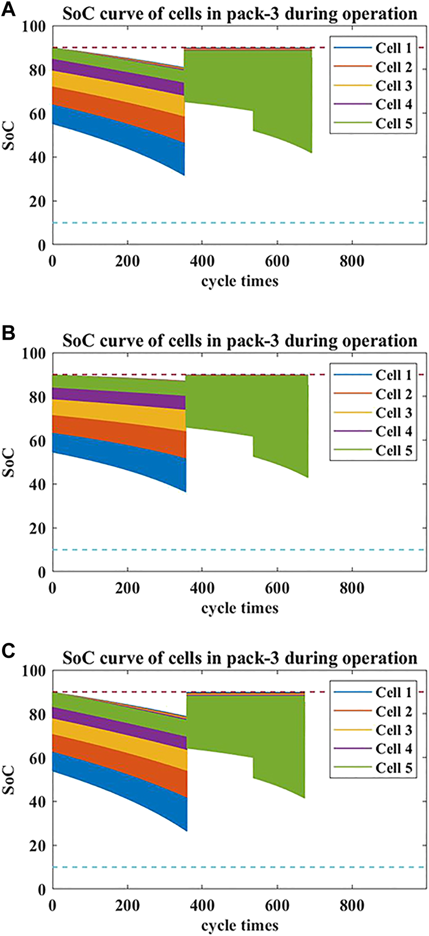
SoC curve of cells in pack-3 during the operation with (A)ηp = 0.95 and ηs = 0.9; (B)ηp = 0.9 and ηs = 0.85; and (C)ηp = 0.85 and ηs = 0.8.
Another two cases are investigated to show the performance of the active multi-layer SoH balancing method with different energy transfer efficiency, as usually, the efficiency of fly-back converter efficiency is between 0.80 and 0.9. The energy transfer efficiency is set as ηp = 0.9, ηs = 0.85 and ηp = 0.85, ηs = 0.8, respectively. The SoC curve is shown in Figures 10B,C. The total cycle time has been decreased to 682 and 674, which means the energy transfer efficiency of the active equalization circuit will slightly affect the effective cycle times. Notice that the SoC level decreases slower in Figure 10B mainly because the setting supplement charging current is closer to the practical error between charging/discharging current than the other two cases under the determined accuracy.
Meanwhile, three more cases are studied to focus on the SoC curves of the proposed method with different initial SoC values. Figure 11A shows the case that the initial SoC values of cells 1–5 are 80–60 with the efficiency ηp = 0.95 and ηs = 0.9. Figure 11B demonstrates another power supplement scheme where several additional charging operations are applied every 150 cycles before the cells are determined as ‘balanced’. This scheme can avoid the out-of-limit SoC condition before the cells are balanced, especially if the balancing process among cells takes a longer cycle time. A case with poor conditions is carried out as shown in Figure 11C that the initial SoC of cells 1–5 are 60–80, with an active equalization circuit efficiency as ηp = 0.85 and ηs = 0.8. The SoC value keeps the limitation by applying the same scheme as in Figure 11B.
FIGURE 11

SoC curve of cells in pack-3 during the operation with (A)ηp = 0.95 and ηs = 0.9, initial SoC 80–60; (B)ηp = 0.95 and ηs = 0.9, initial SoC 80–60, multi additional charge; and (C)ηp = 0.85 and ηs = 0.8, initial SoC 60–80, multi additional charge.
These results prove that the proposed active multi-layer SoH balancing control method can extend the effective cycle times of BESS while satisfying the SoC limitation of the SoC balancing method.
5 Conclusion
This study proposes a modified multi-layer SoH balancing control method for BESS with active equalization circuits to achieve the SoH balancing among cells. The fly-back converter equalization technique and the power distribution balancing method are coordinated to balance the SoH of all batteries at parallel-level and series-level simultaneously. In the parallel layer, the SoH is balanced by controlling the output current of battery packs. The power distribution is determined by the initial equivalent SoH of each pack. In the series layer, the series-connected battery cells among each pack will be equalized individually by offering disparate balancing currents with the fly-back converter equalization technique. The result verifies the effectiveness of the proposed method. It can improve the cycle life by 52.9% compared to traditional active SoC balancing control. Compared with the existing multi-layer SoH equalization scheme, the proposed method can extend the cycle by about 18.3%. Meanwhile, the proposed method can satisfy the SoC limitation during the whole process.
In summary, the primary principle of SoH balancing control is that the SoH among batteries can be balanced by offering different DoD for batteries with different SoH. The simulation has already demonstrated the effectiveness of the proposed method in allocating different output/DoD for different batteries, balancing the SoH of all cells in a BESS, and prolonging the cycle time of the whole system. The proposed method has the potential to be applied to the BESS with lower output power with regular operation, such as the BESS used for market arbitrage. However, there are some challenges to the proposed method. The range of application is not wide enough as the active equalization circuits are not as cheap as passive equalization circuits. Meanwhile, the practical application’s effectiveness is not as good as the simulation because the parameter measurement has some errors. The performance of the proposed method will be reduced when the system misses or gets a wrong equalization point. All these issues will be discussed and resolved by applying the hardware experiment.
Further research will contain the hardware or hardware-in-loop experiment to verify the effectiveness of the proposed method in a hardware environment. The different initial conditions will be considered. In addition, a discussion is proposed as the performance of cycle life extending will be better if all balancing current is determined individually. Thus, an optimal issue will be carried out by setting all balancing currents as the decision variables to verify the discussion and find the optimal value of balancing parameters in the future study. On the other hand, the cost and benefit of the fly-back converter topology will also be investigated to find an optimized trade-off between the raised cost caused by the active topology and the increased benefit brought by the extended cycle time.
Statements
Data availability statement
The raw data supporting the conclusions of this article will be made available by the authors, without undue reservation.
Author contributions
Conceptualization: XL, XY, and XJ; investigation: XL and XY; project administration: XY, LJ, and ZT; supervision: XY, LJ, ZT, and JS; software: XL; validation: XL, XY, and ZT; writing—original draft: XL; and writing—-review and editing: XY, LJ, and ZT.
Conflict of interest
Author XJ is employed by Guangzhou Zhiguang Electric Ltd.
The remaining authors declare that the research was conducted in the absence of any commercial or financial relationships that could be construed as a potential conflict of interest.
Publisher’s note
All claims expressed in this article are solely those of the authors and do not necessarily represent those of their affiliated organizations, or those of the publisher, the editors, and the reviewers. Any product that may be evaluated in this article, or claim that may be made by its manufacturer, is not guaranteed or endorsed by the publisher.
References
1
Azad F. S. Habib A. K. M. A. Rahman A. Ahmed I. (2020). Active cell balancing of Li-Ion batteries using single capacitor and single LC series resonant circuit. Bull. EEI.9 (4), 1318–1325. 10.11591/eei.v9i4.1944
2
Belal E. K. Yehia D. M. Azmy A. M. (2019). Adaptive droop control for balancing SOC of distributed batteries in DC microgrids. IET Gener. Transm. &. Distrib.13 (20), 4667–4676. 10.1049/iet-gtd.2018.6849
3
Bi K. Yang W. Xu D. Yan W. (2020). Dynamic SOC balance strategy for modular energy storage system based on adaptive droop control. IEEE Access8, 41418–41431. 10.1109/access.2020.2976729
4
Boeke U. (2007). “High efficiency flyback converter Technology,” in 2007 power conversion conference (Nagoya, Japan: Nagoya), 1268–1273.
5
Bouchhima N. Gossen M. Schulte S. Birke K. P. (2018). Lifetime of self-reconfigurable batteries compared with conventional batteries. J. Energy Storage15, 400–407. 10.1016/j.est.2017.11.014
6
Cao J. Schofield N. Emadi A. (2008). “Battery balancing methods: A comprehensive review,” in 2008 IEEE vehicle power and propulsion conference (Harbin, China: Harbin, Spet.), 1–6.
7
Cao Y. Abu Qahouq J. A. (2021). Hierarchical SOC balancing controller for battery energy storage system. IEEE Trans. Ind. Electron.68 (10), 9386–9397. 10.1109/tie.2020.3021608
8
Chowdhury S. Bin Shaheed M. N. Sozer Y. (2019). “An integrated state of health (SOH) balancing method for lithium-ion battery cells,” in IEEE energy convers. Congr. Expo. (Baltimore: ECCE), 5759–5763. Spet.-3 Oct. 2019.
9
Dallinger D. (2012). Plug-in electric vehicles integrating fluctuating renewable electricity. 1st edn.Kassel, German: Kassel University Press, 190.
10
Daowd M. Omar N. van den Bossche P. (2011). A review of passive and active battery balancing based on MATLAB/Simulink. Int. Rev. Electr. Eng.6 (7), 2974–2989.
11
Dogger J. D. Roossien B. Nieuwenhout F. D. J. (2011). Characterization of Li-ion batteries for intelligent management of distributed grid-connected storage. IEEE Trans. Energy Convers.26 (1), 256–263. 10.1109/tec.2009.2032579
12
Hu X. Jiang J. Cao D. (2016). Battery health prognosis for electric vehicles using sample entropy and sparse Bayesian predictive modeling. IEEE Trans. Ind. Electron.63 (4), 2645–2656.
13
Huang W. Abu Q. JaberHuang A. W. Abu Qahouq J. A. (2015). Energy sharing control scheme for state-of-charge balancing of distributed battery energy storage system. IEEE Trans. Ind. Electron.62 (5), 2764–2776. 10.1109/tie.2014.2363817
14
Khasawneh H. J. Illindala M. S. (2014). Battery cycle life balancing in a microgrid through flexible distribution of energy and storage resources. J. Power Sources261, 378–388. 10.1016/j.jpowsour.2014.02.043
15
Koseoglou M. Tsioumas E. Jabbour N. Mademlis C. (2020). Highly effective cell equalization in a lithium-ion battery management system. IEEE Trans. Power Electron.35 (2), 2088–2099. 10.1109/tpel.2019.2920728
16
Lee K. M. Lee S. W. Choi Y. G. Kang B. (2017). Active balancing of Li-ion battery cells using transformer as energy carrier. IEEE Trans. Ind. Electron.64 (2), 1251–1257. 10.1109/tie.2016.2611481
17
Li N. Gao F. Hao T. Ma Z. Zhang C. (2018). SOH balancing control method for the MMC battery energy storage system. IEEE Trans. Ind. Electron.65 (8), 6581–6591. 10.1109/tie.2017.2733462
18
Lou W. Lv J. Song W. (2017). “Study on passive balancing characteristics of serially connected lithium-ion battery string,” in 2017 13th IEEE international conference on electronic measurement & instruments (ICEMI) (Yangzhou, China), 489–495.
19
Lu X. Sun K. Guerrero J. M. Vasquez J. C. Huang L. (2014). State-of-Charge balance using adaptive droop control for distributed energy storage systems in DC microgrid applications. IEEE Trans. Ind. Electron.61 (6), 2804–2815. 10.1109/tie.2013.2279374
20
Ma Z. Gao F. Gu X. Li N. Wu Q. Wang X. et al (2020). Multilayer SOH equalization scheme for MMC battery energy storage system. IEEE Trans. Power Electron.35 (12), 13514–13527. 10.1109/tpel.2020.2991879
21
Ma Z. Hao T. Gao F. (2018). “Enhanced SOH balancing method of MMC battery energy storage system with cell equalization capability,” in IEEE applied power electronics conf. And exposition (Charlotte, USA: IEEE), 3591–3597.
22
Meissner E. Richter G. (2003). Battery monitoring and electrical energy management. J. Power Sources116 (1-2), 79–98. 10.1016/s0378-7753(02)00713-9
23
Mukherjee N. Strickland D. (2015). Control of second-life hybrid battery energy storage system based on modular boost-multilevel buck converter. IEEE Trans. Ind. Electron.62 (2), 1034–1046. 10.1109/tie.2014.2341598
24
Neubauer J. Pesaran A. (2011). The ability of battery second use strategies to impact plug-in electric vehicle prices and serve utility energy storage applications. J. Power Sources196 (23), 10351–10358. 10.1016/j.jpowsour.2011.06.053
25
Olsson L. Fallahi S. Schnurr M. Diener D. van Loon P. (2018). Circular business models for extended EV battery life. Batteries4 (4), 57. 10.3390/batteries4040057
26
Ouyang Q. Chen J. Zheng J. Fang H. (2018). Optimal cell-to-cell balancing topology design for serially connected lithium-ion battery packs. IEEE Trans. Sustain. Energy9 (1), 350–360. 10.1109/tste.2017.2733342
27
Pattipati B. Sankavaram C. Pattipati K. (2011). System identification and estimation framework for pivotal automotive battery management system characteristics. IEEE Trans. Syst. Man. Cybern. C41 (6), 869–884. 10.1109/tsmcc.2010.2089979
28
Probstl A. Park S. Narayanaswamy S. (2018). “Soh-Aware active cell balancing strategy for high power battery packs,” in 2018 design, automation & test in europe conference & exhibition (DATE) (Dresden, Germany), 431–436.
29
Shahriari M. Farrokhi M. (2013). Online state-of-health estimation of VRLA batteries using state of charge. IEEE Trans. Ind. Electron.60 (1), 191–202. 10.1109/tie.2012.2186771
30
Tran D. Khambadkone A. M. (2013). Energy management for lifetime extension of energy storage system in micro-grid applications. IEEE Trans. Smart Grid4 (3), 1289–1296. 10.1109/tsg.2013.2272835
31
Yang B. Wang J. Cao P. Zhu T. Shu H. Chen J. et al (2021). Classification, summarization and perspectives on state-of-charge estimation of lithium-ion batteries used in electric vehicles: A critical comprehensive survey. J. Energy Storage39, 102572. 10.1016/j.est.2021.102572
32
Zhang Y. Xu Y. Yang H. Dong Z. Y. Zhang R. (2020). Optimal whole-life-cycle planning of battery energy storage for multi-functional services in power systems. IEEE Trans. Sustain. Energy11 (4), 2077–2086. 10.1109/tste.2019.2942066
33
Ziegler A. Oeser D. Arndt B. (2018). “Comparison of active and passive balancing by a long term test including a post-mortem analysis of all single battery cells,” in 2018 international IEEE conference and workshop in óbuda on electrical and power engineering (Budapest, Hungary: CANDO-EPE), 000015–000020.
Summary
Keywords
battery-based energy storage system, state of health, state of charge, battery equalization, fly-back converter
Citation
Li X, Yin X, Tian Z, Jiang X, Jiang L and Smith J (2022) Multi-layer state of health balancing control for a battery-based energy storage system to extend cycle life based on active equalization circuits. Front. Energy Res. 10:966422. doi: 10.3389/fenrg.2022.966422
Received
10 June 2022
Accepted
30 August 2022
Published
30 September 2022
Volume
10 - 2022
Edited by
Sudhakar Babu Thanikanti, Chaitanya Bharathi Institute of Technology, India
Reviewed by
K. Deepa, Amrita Vishwa Vidyapeetham University, India
Jian Yang, Central South University, China
Updates
Copyright
© 2022 Li, Yin, Tian, Jiang, Jiang and Smith.
This is an open-access article distributed under the terms of the Creative Commons Attribution License (CC BY). The use, distribution or reproduction in other forums is permitted, provided the original author(s) and the copyright owner(s) are credited and that the original publication in this journal is cited, in accordance with accepted academic practice. No use, distribution or reproduction is permitted which does not comply with these terms.
*Correspondence: Lin Jiang, ljiang@liverpool.ac.uk
This article was submitted to Smart Grids, a section of the journal Frontiers in Energy Research
Disclaimer
All claims expressed in this article are solely those of the authors and do not necessarily represent those of their affiliated organizations, or those of the publisher, the editors and the reviewers. Any product that may be evaluated in this article or claim that may be made by its manufacturer is not guaranteed or endorsed by the publisher.