 Mohamed Murshid Shamsuddeen
 Sung Kim2
 Mohammad Abu Shahzer
 Jin-Hyuk Kim
- 1Convergence Manufacturing System Engineering (Green Process and Energy System Engineering), Korea University of Science & Technology, Daejeon, South Korea
- 2Carbon Neutral Technology R&D Department (Fluid Machinery), Korea Institute of Industrial Technology, Cheonan, South Korea
The flow in a double-suction twin-volute five-stage centrifugal pump is studied numerically using Computational Fluid Dynamics (CFD) calculations. The pump performance at various flow rates obtained numerically are compared with the theoretically results. The deterioration in pump performance at various flow rates were investigated to find the losses associated with the design of the pump components. The stage-wise performance analysis revealed the hydraulic losses associated with the second-stage impeller due to highly swirled flow exiting from the first stage twin-volute. The fluid exiting the twin-volute have a high circumferential velocity than its radial component leading to a high pre-swirl at the inlet of stage 2 impeller. In order to regulate the high pre-swirl, baffle plates were installed at the exit of the twin-volute. Three baffle plate configurations were studied and their effects on the pump performances were compared. The vertical configuration improved the pump efficiency by 1.36% and head by 6.04% while the horizontal configuration improved them by 2.42% and 5.96% respectively. The 4-plate baffle configuration improved the pump performance by only a small margin. The installation of the baffle plates also improved the stage performances in both design and off-design conditions. The horizontally installed baffle plates were then tested at various angles. The plates installed at 300° clock-wise increased the pump head by 9.08% and efficiency by 3.87%. A comprehensive analysis of the flow physics inside the pump are also presented.
1 Introduction
In the recent years, CFD calculations have been extensively used in the early stages of product development even before manufacturing particularly in turbomachinery. The pump designers, in order to respond to rapid fluctuations in market requirements and to reduce development costs, use CFD methods to test their designs for their hydraulic performances prior to manufacturing. This eliminates the need to manually test several designs at various flow conditions in a turbomachinery test facility in the design stage. The design faults occurring at this stage can be identified and corrected by this technique. The design faults of a multi-stage centrifugal pump is identified and corrected in this study using CFD tools.
A 5-stage centrifugal pump was designed for application in several industries where a high head and high flow rate was required to pump water or other chemicals over a long distance. The pump was specially developed for unique applications such as boiler feedwater, reactor charge service, water injection, power recovery, seawater injection, and other high-pressure services (McGuire, 2019). In our previous study, the pump’s design feasibility study demonstrated its ability to handle different fluids at vast flow rates ranges (Shamsuddeen et al., 2021b). A stage-to-stage loss analysis revealed the areas of performance degradation between stage 1 and stage 2. Two design proposals were made to correct the losses and improve the pump performance. One of the solutions was to install an additional guide vane between the first and second stage to correct the flow angle. This has been investigated previously (Shamsuddeen et al., 2021a), which showed significant improvement in the pump performance. However, the installation of an additional guide vane increased the length of the pump which accounted for additional manufacturing costs. The second solution was to install baffle plates at the twin volute exit such that it can decrease the losses without altering the pump dimensions. The proposal to install baffle plates at the exit of the twin-volute is presented in this study.
Installation of baffle plates is a standard practice to regulate the swirling flow in pumps. (Sato et al., 2010, 2011; Tanaka et al., 2012) studied the cavitation characteristics of a single-stage double suction volute pump with baffle plates. (Li et al., 2014; Li et al., 2018) investigated the effect of baffle plate on a single-stage self-priming pump. The baffle plate was found to prevent the formation of swirling flow in the pump chamber and increase the self-priming performance of the pump. The head and efficiency of the pump were increased when the baffle plate was installed at 36° in the clock-wise direction. (Luo et al., 2019) studied three baffle plate configurations in a low specific speed centrifugal pump and found that baffle plates helped in decreasing the pressure pulsation amplitude in the volute. (Lin et al., 2020) studied the effect of an inlet guide vane installed at the inlet of a centrifugal pump and found to reduce the hydraulic losses and improve the hydraulic performance. (Lin et al., 2022) further studied the effect of installation angle of the inlet guide vane and found that the head and efficiency improved at 25° angle. (Wang et al., 2017; Koranteng Osman et al., 2019) installed baffle plates at the inlet channel between the suction chamber and impeller in a two-stage axially split centrifugal pump and found to improve the head by a great margin. (Shukla et al., 2017) improved the pump characteristics at off-design conditions after modifying the baffle plate geometry in a single-stage double-suction centrifugal pump. (Wei et al., 2021) added baffle plates at the centrifugal pump inlet to suppress the pump vibration and cavitation instabilities. (Zhao and Zhou, 2022) studied the effect of adding a small plate (tiny blade) in the impeller flow passage to obtain a stable pump operation. From these studies, it is evident that the installation of baffle plates not only regulates the swirling flow but also improve the pump performance.
Several researchers have installed baffle plates for various purposes especially in single-stage pumps. However, the effects of baffle plates in a 5-stage centrifugal pump at the twin-volute between two stages and the significance of the installation location and angle are not found in literatures. In this study, the effects of the baffle plate on the multistage pump performance and on individual stages are studied in depth to determine its role in mitigating hydraulic losses and improving pump efficiency. Moreover, the significance of the baffle plate installation location and angle are studied and design recommendations are provided based on the performance of the pump. The internal flow physics observed inside the pump with the installation of the baffle plates are presented in detail. This scientific study aids the pump designers to correct their design flaws prior to manufacturing the pump.
2 Description of the models
The first stage of the centrifugal pump comprise of a double-suction impeller inscribed in an inlet passage followed by a twin-volute. The twin-volute is staggered at 180° to offset the radial forces to each other. A single-suction impeller, a diffuser and a return vane are assembled in the second stage and is repeated for stages 3 and 4. The fifth stage has an impeller similar to the previous stages, but the diffuser is larger and is secured to the outlet volute. The impeller is engineered to reach a high head with maximum efficiency, while a diffuser is designed to increase pressure in its vanes while reducing pressure gradients in the return vanes. Figure 1 shows the centrifugal pump design. The proposed 5-stage pump is assembled in such a way that the number of stages may be adjusted to obtain the Net Positive Suction Head Required (NPSHr) and flow rate requirements. They are usually determined by the API BB5 pump standards (Api, 1995). The specification and the dimensions of the pump is given in Table 1.

FIGURE 1. 3D design of the five-stage centrifugal pump.
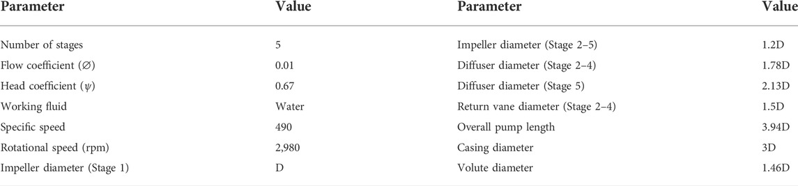
TABLE 1. Pump specification and dimensions.
Three baffle plate designs were studied for its effect to control the swirl components of the fluid exiting the volute. The selected design is further studied to find the optimal angle of installation such that the overall efficiency and head of the pump is further improved. Figure 2 shows the reference volute design along with the three baffle plate designs. The baffle plates were installed vertically, horizontally, and combined horizontal and vertical design at the volute exit. Baffle plates are shaped according to the shape of the volute casing with 10 mm thickness, 46.5 mm height and 62.8 mm width.
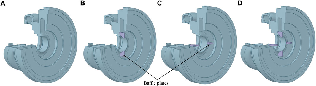
FIGURE 2. Volute configurations (A) Reference design (B) Baffle 1 (C) Baffle 2 (D) Baffle 3.
3 Numerical model
3.1 Geometry and grid generation
The geometrical design process of the centrifugal pump structure was done using a CAD software, obtained from a geometrically similar scaled-down pump model used for low-flow rate applications provided by the manufacturer. ANSYS Bladegen tool was used to generate the impeller, diffuser and the return vane geometries. The fluid domains of all the components were extracted using ANSYS Space Claim. The baffle plates were added by modifying the geometry of the volute fluid domain. The fluid domains were then meshed using various meshing tools supplied by ANSYS. The suction chamber, the twin-volute, diffuser vanes, return vanes, and the outlet chamber were meshed using tetrahedral grids while the impellers were meshed using hexahedral grids. The generated grids are then tested for grid independency so that the results do not show a discrepancy based on the grid size. To identify the most appropriate grid size for the study, the grids of first and second stages were studied independently instead of the entire pump since third, fourth and fifth stage grids are a repetition of the former stages. Multiple layers of boundary mesh were applied along the impeller suction and pressure side surfaces to resolve the boundary layers and keep the y+ value below 30. Diffuser and return channel grids were also given similar boundary layers. One passage of each component; impeller, diffuser and return vanes were modeled for reducing the computational costs.
The most accurate approach for a grid convergence research is the grid convergence index (GCI), which is obtained using the Richardson extrapolation method (Celik et al., 2008). For a key variable collected from three independent sets of grids with considerable resolutions, an estimated relative error (ea) and fine grid convergence index (GCIfine) are computed. The key variables studied are the efficiency (η) and the head (H) generated by the centrifugal pump. The GCIfine can be calculated from the following formula:
where r is the ratio between two grids in comparison.
The GCI values of the 2 stages are shown in Table 2.
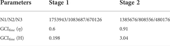
TABLE 2. Calculation of GCI values for the 2 stages.
The GCI values of both stages and for both variables are less than 4% for the fine mesh N1. Since the GCI values of both variables are reasonable, grid size N1 can be considered optimal, and additional grid refining is not required. Generating the grids for all pump stages using N1 grid size of stages 1 and 2 summed upto 6.25 million nodes. The optimum grids of the impeller, volute and the diffuser are shown in Figure 3.
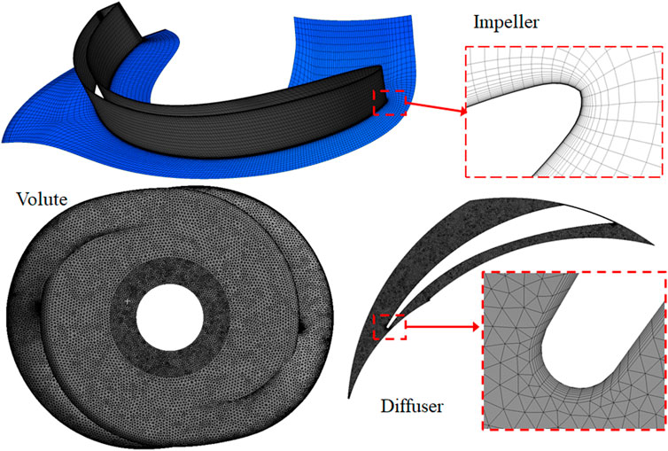
FIGURE 3. Optimal grid of the impeller, volute and diffuser.
The grids of all the components generated through the meshing software were assembled together in CFX-Pre module of the ANSYS CFX package. The initial and boundary conditions of the assembled fluid domains were defined for the inlet, outlet, boundary walls, periodic faces, and the interfaces between each component in this module. The pump inlet was defined at atmospheric pressure while the outlet was defined with mass flow rate. The boundary walls were defined as stationary walls and the periodic faces of the single passage domains were defined periodic with appropriate pitch ratios. All components where defined as stationary domains except for the impeller domains which rotates along the z-axis. The interfaces between the stationary and rotating domains were defined as mixing-plane (stage) interface due to a high pitch ratio between the components. A mesh connectivity is established at all interfaces to interconnect the non-conformal elements between the domains using a General Grid Interface (GGI). By means of an intersection algorithm, the GGI determines the connectedness between the grids on each side of the interface (ANSYS Inc, 2011). Water is used as the working fluid in the pump.
The governing equations for the fluid transportation were defined in a steady-state setting based on the Reynolds-averaged Navier-Stokes (RANS) formulas for incompressible fluids which are well-documented in a variety of sources (ANSYS, 2013; Siddique et al., 2017). In order to accurately model the turbulent behavior of the fluid inside the pump, the Shear Stress Transport (SST) turbulence model was used coupled with the standard wall function (Menter, 1994). The SST model is a widely used method for modeling turbulent flow in rotating fluid machinery and has been validated by several researchers from around the world (Kim et al., 2019a; Kim et al., 2019b). In the near-wall region and freestream area, the SST model uses the k–ω and k–ε equations, respectively, along with a blending function that guarantees seamless transitions between these models.
The computations are carried out using an Intel Xeon CPU with a clock speed of 2.4 GHz equipped with 56 cores and 128 GB RAM capacity. The computation time for each simulation was 18–20 h to achieve convergence.
4 Pump performance
The pump performances are expressed in terms of head coefficient (ψ), flow coefficient (φ), and efficiency which are calculated using the following formulas:
where D, g, n, P and ρ corresponds to the impeller diameter, acceleration due to gravity, rotational velocity, input power and fluid density, respectively.
A dynamically similar model pump design given by the supplier served as the basis for the proposed centrifugal pump’s preliminary design. The model pump was a scaled-down model used for low flow rate industrial applications. The current pump prototype is the scaled-up design particularly to handle fluids at high flow rates and high head operations. The pump affinity rules are employed to extract the dynamically similar prototype design, as is seen below:
where the variables denoted by subscriptions 1 and 2 refer to the model and the prototype. The variables Q, n, H and P corresponds to the flow rate, rotational velocity, head and the input power, respectively.
The performance of the pump design derived from affinity laws is determined theoretically and then validated numerically using CFD tools. The theoretical prediction was confirmed by the projected trend of the head and efficiency curves at different flow rates. With an error margin of less than 8%, the graphs obtained from the CFD analysis are in satisfactory agreement with the theoretical results as shown in Figure 4. Due to the general constraints of the steady-state simulation with a simplified geometrical model, and the disregarding of losses in the numerical simulations, the computational accuracy does have a certain impact on the error margin. Therefore, the generated CFD results are suitable for further study since this is an initial design feasibility assessment prior to experimental testing without accounting for unexplained mechanical losses.
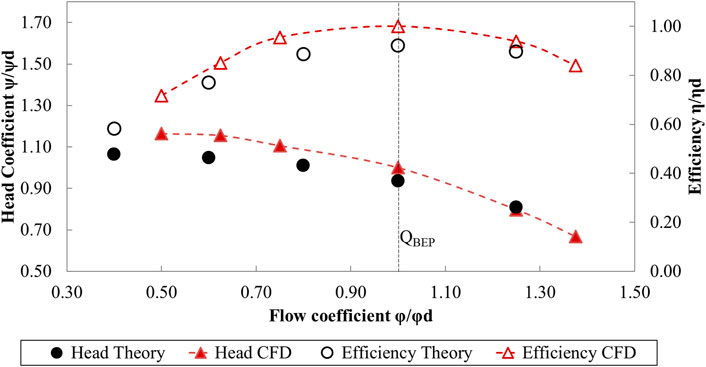
FIGURE 4. Comparison of theoretical calculations and numerical simulations.
Figure 5 compares the pump’s performance comparison between different baffle plate designs. A significant increase in the head is witnessed at each flow rate for all cases with the baffle plates, with baffle 3 design having the highest head. The head at the QBEP increased by 6.04%, 5.97%, 7.07% for baffle 1, 2 and 3 designs, respectively compared to the reference pump. A fair increase in efficiency is also observed for the pump with baffle plates at large flow rates. The efficiency at the design point improved by 1.36%, 2.43%, and 0.37% respectively for baffle designs 1, 2, and 3 in comparison to the reference pump. The baffle 2 design shows the highest efficiency among the three designs. A similar increase in efficiency of 2.41% is observed at the high flow rate for baffle 2. However, the improved pump performance comes at the expense of slightly higher power consumption. With the installation of baffle plates, power consumption rose by 3.46 percent at the QBEP and by 8.46 percent at the highest flow rate condition for baffle 2 model. Even while power consumption increases at maximum flow rate, the gain in efficiency and head is sufficient to compensate for the difference. Therefore, with the installation of baffle plates, the pump’s overall performance has considerably improved.
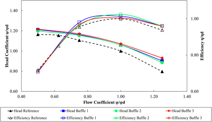
FIGURE 5. Performance comparison of different baffle designs with the reference pump.
In a multistage centrifugal pump, individual stage performance is just as critical as the total pump performance. Studying the efficiency and head of individual stages provides insight into the local characteristics of the pump and aids in identifying the losses associated with the pump. The stage-wise head is calculated by measuring the total pressure gradient at the entry and exit of each stage. The stage-wise efficiency is calculated from the input power measured by the torque on the impeller at that stage, the flow rate through the stage outlet and the stage-wise head put together in the efficiency equation. Figure 6 shows the stage-by-stage efficiency and head coefficient curves of the reference pump. At the low flow rate, the efficiency of the pump is nearly identical at all stages. Except for stage 2, all stages’ hydraulic efficiency improves as the flow rate increases. Beyond QBEP, the efficiency and head at stage 2 plummets at a rapid pace. The reference pump’s high decline in efficiency and head suggests a significant loss at the stage 2. The performance of the pumps with baffle plates are compared with the reference pump at the second stage in Figure 7. The installation of baffle plates has contributed to head loss recovery at the second stage at all flow rates. A difference of 63.7%, 57.3%, and 76.75% in head are observed for baffle designs 1, 2, and 3, respectively at the QBEP. Meanwhile, the efficiency increased substantially at high flow rates for all baffle plate models thereby decreasing the pump stage losses. The baffle plate 2 model has the highest efficiency at stage 2 with an increase of 29.13% at the QBEP. A small improvement in performance can also be found in the subsequent stages as well. Installation of baffle plates has not only increased the stage 2 performance significantly, but it also enhanced the performance at all stages. The stage-to-stage improvement in performance has collectively reflected in the overall pump performance as seen in Figure 5.
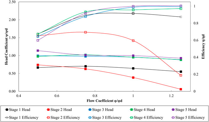
FIGURE 6. Stage-wise performance of the reference pump.
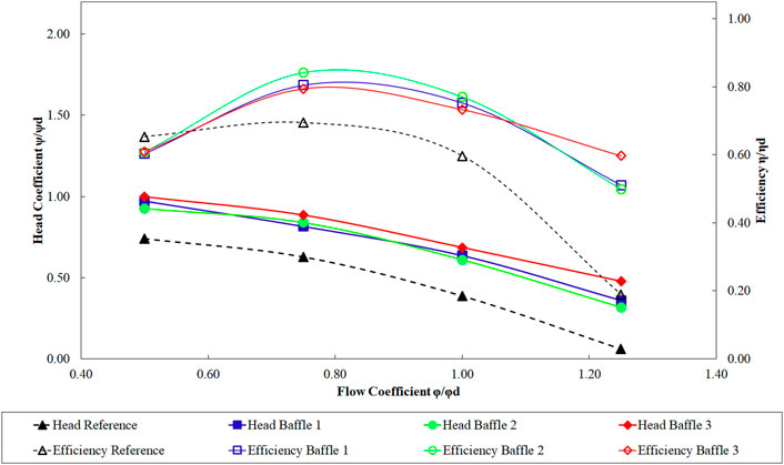
FIGURE 7. Performance comparison of stage 2.
To fully comprehend the flow dynamics at the volute-impeller interface, a thorough examination of the losses seen at stage 2 and the role of the baffle plates in reducing these losses is required. The pump running at the design point is chosen for the in-depth examination since it is operated at the design point more frequently than others. The impeller, diffuser, and return vanes make up the second stage. For the reason that the losses are most noticeable at the impeller’s inlet, the loss analysis is limited to the flow through the volute to the second stage impeller. Unless otherwise noted, here onwards, the word ‘impeller’ refers to the second stage impeller.
Figure 8 displays the blade loading at the center-span of the impeller from leading edge to trailing edge for the 4 pump designs at QBEP. The maximum value of the pressure is used to normalize the parameter. The reference pump shows a significant drop in pressure along the leading edge, highlighting the location of the peak loss. Cavitation bubbles may form as a result of such rapid pressure drops, which can easily cause damage to the impeller. The baffle plates, installed at the exit of the volute, reduced the pressure loss at the impeller’s leading edge by a great margin. The pressure drop at the leading edge has been curtailed by 88.37%, 79.49%, and 143.02% by the pump with baffle plates design 1, 2, and 3, respectively. The overall improvement in the blade loading curve is measured by calculating the weighted average of the pressure distribution which provides an accurate representation of the average change in percentage of the entire curve. The blade loading curves of baffle designs 1, 2, and 3 has improved by a weighted average of 39.4%, 37.62%, and 52.98%, respectively compared to the reference blade. The impact of the baffle plates on stage 2 impeller in improving the blade loading can also been seen in the subsequent stages as well.
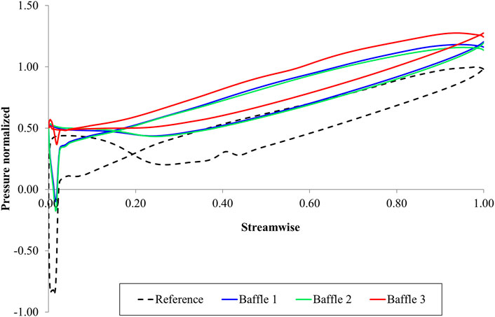
FIGURE 8. Blade loading comparison of the second stage impeller at QBEP.
4.1 Internal flow field analysis
The behavior of the fluid passing through the volute and the second stage impeller is investigated in order to discover the reasons of the losses and to study how baffle plates aid in the flow correction. The fluid exiting the impeller at stage 1, separates into the two arms of the symmetrical twin-volute, continues along the volute surface, and rejoins at the volute’s outlet. The velocity vector and the pressure distribution at the exit of the twin-volute of the 4 pumps are shown in Figure 9. In the reference pump (Figure 9A), a low-pressure region is detected around the shaft due to a high circumferential velocity formed due to the rotating flow incoming from the two arms of the twin-volute. The rotating flow exits the volute after 2-3 revolutions. At the volute outlet, the fluid has a stronger circumferential velocity than the axial velocity, resulting in a pre-swirl at the leading edge of the stage two impeller. The circumferential velocity is found to be approximately 5 times higher than the axial velocity. This creates recirculation zones between the impellers causing vertices to develop at the pressure side of the blade The vortices formed at the flow passage of the second stage impeller is shown in Figure 11A. These vortices create obstruction to the flow leading to the development of blockage effect on the flow through the impeller. These blockages have a direct impact on the stage-wise performance resulting in an overall performance loss of the pump.
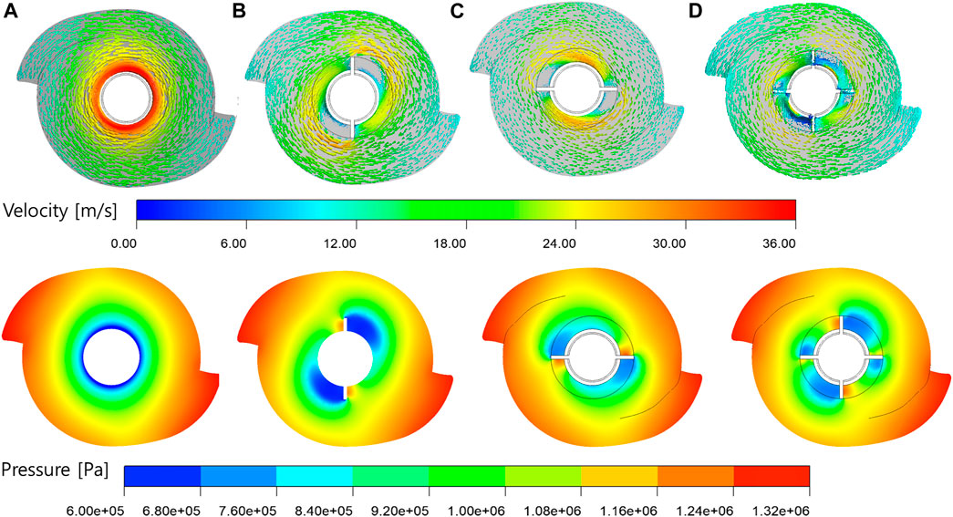
FIGURE 9. Velocity vector and pressure contour at the volute exit for (A) Reference pump (B) Baffle 1 (C) Baffle 2 (D) Baffle 3 designs.
With the introduction of the vertical baffle plates (baffle plate design 1) as shown in Figure 9B, the incoming flow from the two arms of the volute, strike on the baffle plate after a complete rotation. The fluid incoming from the top arm completes a revolution and strikes on the top baffle plate, while the fluid incoming from the bottom arm completes a revolution and strikes the bottom plate. The fluids striking the baffle plates loses its circumferential velocity and immediately changes its direction to exit the volute. The pre-swirl formation at the leading edge of the impeller is reduced thereby reducing the formation of vertices between the blades. The formation of vortices at the impeller flow passage has decreased considerably at the pressure side of the impeller as shown in Figure 11B. There are still few vortices observed at the leading edge and trailing edge of the runner. The reduction in vertex formations decrease the blockage to the flow through the impeller which directly contributes to decreasing head losses and improving the stage performance. The baffle plate design 1 however, has a drawback at the downstream of the plates. Low-pressure regions are formed behind the plates causing a cavity at the volute exit. This is due to the vertical orientation of the plates against the incoming flow direction. This low-pressure zone may cause cavitation of the plates and decrease the pump life rapidly.
Installing the baffle plates horizontally (baffle plate design 2) functions similarly to the design 1 by allowing the rotational flow to change its direction and exit the volute. The flow incoming from the top arm completes one revolution and strikes the left plate, while the flow from the bottom arm completes one revolution and strikes the right plate as shown in Figure 9C. The intensity of the low-pressure regions formed behind the plates have decreased by 16.53% compared to the vertical plates since the plates are installed parallel to the incoming flow. The change in flow direction of the fluid exiting the volute towards the impeller is shown in Figure 10. The fluid striking on the baffle plate, loses its momentum by half and turns towards the exit. The streamlines with high velocity, exit the volute without impact with the baffle plates. The fluid particles behind the plate due to the low-pressure zone loses all its momentum and recirculates at that region. However, the area of the recirculation zone has decreased compared to the vertical design. The effect of the change in installation location can be observed the behavior of the vortex formation in the impeller as seen in Figure 11C. The vortices formed at the leading edge and trailing have decreased while a small increase in vortex volume is observed at the pressure side.
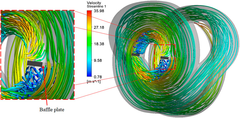
FIGURE 10. Velocity streamline at the volute exit of baffle 2 design.
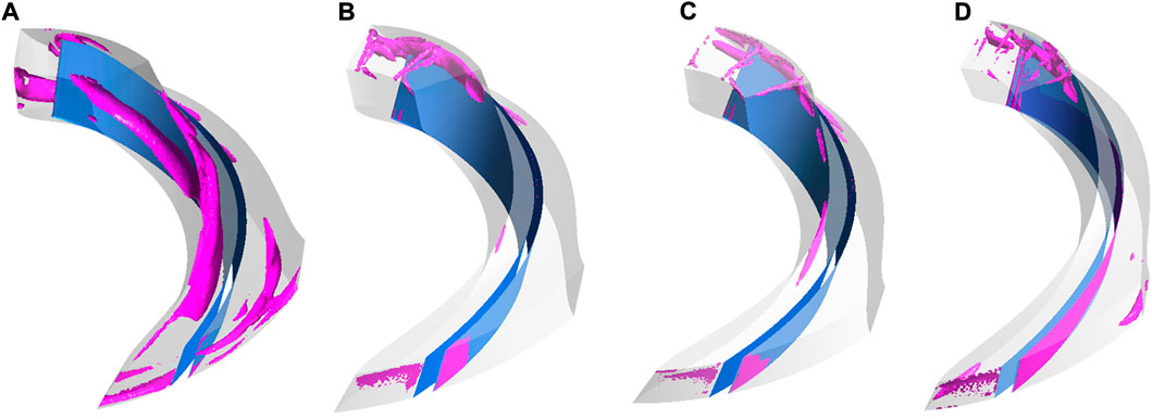
FIGURE 11. Comparison of vortex formation at the second stage impeller at QBEP (velocity swirling strength = 1,500 s−1) for (A) Reference pump (B) Baffle 1 (C) Baffle 2 (D) Baffle 3 designs.
The baffle 3 design is a combination of vertical and horizontal plates. The flow incoming from the two arms of the volute, strike on the baffle plates before completing a full revolution as shown in Figure 9D. Several low-pressure recirculation zones are created at the downstream of the baffle plates causing more harm than good. However, the vortex formation at the impeller pressure side has been completely eliminated as seen in Figure 11D. This comes at a cost of small vortices forming at the suction side and at the trailing edge.
From Figure 11, it can be observed that the vortices formed between the impellers at stage two in the reference model has been diminished with the installation of baffle plates. The formation of these vortices at the impeller obstructs the incoming flow by creating a blockage effect thereby decreasing the pressure at the impeller pressure-side. This is further explained by drawing the velocity triangle at the impeller leading edge. The velocity triangles of the 4 models are shown in Figure 12. The angle β represents the relative flow angle, α represents the absolute flow angle, W is the relative velocity, C is the absolute velocity and U is the blade velocity. The velocity triangle of baffle 2 design shows a decrease in the relative angle from β = 128.51° to β = 88.1°. The magnitude of the relative velocity increased by 9.1% while the absolute velocity decreased by 36.26%. The significance of this flow angle correction can explain the decrease in the circumferential velocity at the leading edge of the impeller. The circumferential velocity decreased by 35.84% with horizontal installation of baffle plates.
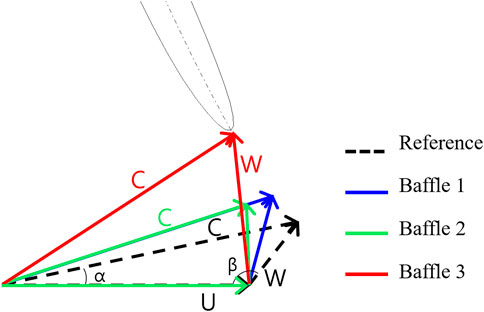
FIGURE 12. Velocity triangles at the impeller inlet of the pump models.
The pump performance comparison and the internal flow field analysis showed that the baffle plate designs have succeeded in mitigating the losses associated with the twin-volute design. However, it is observed that there is still room for improvement in the baffle plate design as certain low-pressure stagnation zones are observed downstream of the plates. Among the three baffle designs, the baffle 2 pump is chosen for further analysis. The decision to choose the baffle 2 design over other designs for is based on the pump performance. The performance curve of different baffle designs (Figure 5) shows that the baffle 2 has the highest efficiency at the design point. Another important parameter in the decision making is the power consumption of the pump. The power consumption increased with the installation of the plates. At the QBEP, the baffle 3 pump consumed the highest power at 6.68% higher than the reference pump while baffle 1 and 2 designs consumed 4.62% and 3.45% higher power, respectively.
5 Study on baffle plate installation angle
The baffle plate installation angles are studied with an aim to reduce the low-pressure zones observed at the downstream of the plates and to improve the pump performance. The baffle plate design 2, being the most efficient design among others, is selected for this study. The baffle plates are installed at angles 45°, 315°, 300°, and 280° as shown in Figure 13. The angles 315°, 300°, and 280° correspond to −45°, −60°, and −80° in the anti-clockwise direction, respectively.

FIGURE 13. Baffle plate design 2 installed at various angles. (A) 45° (B) 315° (C) 300° (D) 280°.
The angle of installation of the baffle plates has significant effect on the performance of the pump. The efficiency and head at the QBEP are plotted in Figure 14. The head and efficiency parameters are normalized with the head and efficiency of the baffle 2 design for ease of comparison. The subscript “B2” corresponds to the baffle 2 design installed horizontally at 0°. The baffle plate design 2 installed at 300° shows the highest efficiency and head with an increase of 1.41% and 2.94%, respectively compared to the baffle plate design 2 installed at 0°. This is because, the pressure behind the baffle plate as shown in Figure 15 has been increased by 27.29%, thereby eliminating any low-pressure zones at the volute exit. As a result, the velocity streamline plot shows low volute exit velocity for baffle plate at 300° than for other angles. The blade loading curve showed an increase in weighted average of 15.66%, 17.83%, and 8.17% for the 315°, 300°, and 280°, respectively compared to B2. Meanwhile, rotating the baffle plate to +45° showed negative impact since it is against the flow direction. The efficiency, head and weighted average of blade loading curve decreased by −0.97%, −1.41%, and −3.31%, respectively. Therefore, the baffle plate design 2 installed at an angle of 300° is selected for manufacturing.
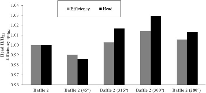
FIGURE 14. Efficiency and head comparison of baffle 2 design at various angles.
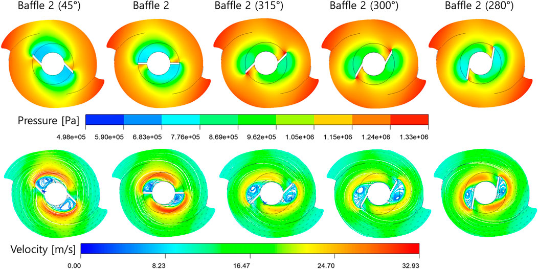
FIGURE 15. Pressure and velocity streamlines at volute exit for different baffle plate angles.
In comparison with the initial reference pump (without baffle plates), the selected design (baffle plates installed at 300°) exhibited substantial improvement in the overall pump performance. The efficiency of the pump at QBEP improved by 3.87% while the head increased by 9.1%. The overall blade loading distribution of the second stage impeller improved by a weighted average of 62.16%. The fluid pressure at the exit of the volute increased by 52.45% while the circumferential velocity weakened by −43.88%. Thereupon, the selected design is recommended for manufacturing and testing in a test facility.
6 Conclusion
A multistage centrifugal pump developed for high-head and high flow rate application in industrial flows, showed performance degradation due to faulty design. The 5-stage pump consisting of a double-suction impeller and a twin volute in the first stage; impeller, diffuser and return vanes in the consecutive stages exhibited head losses at the second stage. The in-depth flow analysis revealed that the flow exiting from stage 1 to stage 2 had high radial forces than axial force, leading to formation of recirculation zones and vortices at the second stage impeller. The fluid exiting the twin-volute had a high circumferential velocity contributing to excessive pre-swirl formation at the impeller inlet. Installation of baffle plates at the volute exit weakened the circumferential velocity exiting the volute thereby regulating the pre-swirl formation at the second stage impeller inlet. Three baffle plate designs were tested for its loss mitigating capability and performance enhancement. A pair of vertical plates (baffle 1), horizontal plates (baffle 2) and a combination of both (baffle 3) were studied using computational fluid dynamic tools. The effects of the baffle plates on the pump performance compared with the initial pump model are:
1. An increase in head of the pump were observed for pump with baffle plates at all flow rates. At the design point, the pump with baffle plate showed a rise in pump head by 6.04%, 5.97%, 7.07% for baffle 1, 2, and 3 designs, respectively.
2. The efficiency of the pump had little change at low flow rates but at the high flow rates, the efficiency improved by 1.36%, 2.43%, and 0.37% respectively for baffle designs 1, 2, and 3.
3. The stage-to-stage analysis showed the loss mitigation at the second stage by the installation of the baffle plates in the first stage. The stage head loss decreased by 63.7%, 57.3%, and 76.75% while stage efficiency rose by 26.1%, 29.13%, and 22.84% for baffle plate designs 1, 2, and 3, respectively.
4. Plotting the blade loading chart over the blade mid-span revealed a low-pressure point at the leading edge which may cause cavitation of the pump impeller. The blade loading chart improved with a weighted average of 39.4%, 37.62% and 52.98% with the installation of baffle plates 1, 2, and 3 respectively.
5. Understanding the change in flow phenomena with the baffle plate installation was facilitated by a comprehensive flow field investigation at the volute-impeller interface. The baffle plates prevented the fluid from swirling within the volute before exiting towards the impeller. The fluid incoming from the volute arms strike at the baffle plate, thereby changing its course towards the second stage impeller.
6. Baffle plate design 2 being the most efficient design among the proposed designs were later tested at various installation angles to further enhance the effectiveness of the plates. The plates were studied at 45°, 315°, 300°, and 280° at the same flow conditions.
7. The baffle plate installed at 300° is found to be the most effective design with an increase in efficiency by 3.87% and head by 9.1% at the design point compared to the reference pump.
The installation of the baffle plates proved to be successful in mitigating losses associated with the second stage of the pump and thereby increasing the overall pump performance. The effect of the baffle plates would be tested experimentally prior to manufacturing the final prototype and is an ongoing research. The pump cavitation analysis and fatigue test of the twin-volute with the baffle plates using FSI techniques is the future work of this study. The baffle plate shape optimization can be carried out if necessary. The pump design and redesign technique using CFD in the design phase prior to manufacturing has indeed saved a certain amount of the testing cost before product commercialization. This study provides design recommendations to the pump designers to decrease the hydraulic losses and improve the pump performance in the design stage itself.
Data availability statement
The raw data supporting the conclusion of this article will be made available by the authors, without undue reservation.
Author contributions
Conceptualization: J-HK, SK, MMS, and S-BM, methodology: MMS; software: MMS; validation: J-HK and MMS; formal analysis: MMS investigation: MMS and SK; resources: J-HK; data curation: MMS and MAS; writing—original draft preparation: MMS; writing—review and editing: MMS, and MAS; visualization: MMS; supervision: J-HK; project administration: J-HK; funding acquisition: J-HK. All authors have read and agreed to the published version of the manuscript.
Funding
This work was supported by Korea Institute of Energy Technology Evaluation and Planning (KETEP) grant funded by the Korea government (MOTIE) (2021202080026A, Development of Variable Operating Technology for Medium and Large Size Pump) and partially supported by a grant (No. JB220011) from the Korean Institute of Industrial Technology (KITECH).
Conflict of interest
The authors declare that the research was conducted in the absence of any commercial or financial relationships that could be construed as a potential conflict of interest.
Publisher’s note
All claims expressed in this article are solely those of the authors and do not necessarily represent those of their affiliated organizations, or those of the publisher, the editors and the reviewers. Any product that may be evaluated in this article, or claim that may be made by its manufacturer, is not guaranteed or endorsed by the publisher.
References
ANSYS (2013). “ANSYS BladeModeler,” in ANSYS TurboSystem user’s guide (Fort Cannon, PA, USA: ANSYS, Inc).
ANSYS Inc (2011). “Domain interfaces,” in ANSYS CFX-pre user’s guide (Pennsylvania, USA: ANSYS, Inc.), 146–147.
API (1995). API 610 - centrifugal pumps for petroleum, heavy duty chemical, and gas industry services.
Celik, I. B., Ghia, U., Roache, P. J., Freitas, C. J., Coleman, H., and Raad, P. E. (2008). Procedure for estimation and reporting of uncertainty due to discretization in CFD applications. J. Fluids Eng. Trans. ASME 130, 0780011–0780014. doi:10.1115/1.2960953/444689
Kim, J. H., Cho, B. M., Kim, S., Lee, Y. K., and Choi, Y. S. (2019a). Detailed flow characteristic analysis of a three-stage centrifugal pump at design and off-design conditions. IOP Conf. Ser. Earth Environ. Sci. 240, 092004. doi:10.1088/1755-1315/240/9/092004
Kim, J. H., Cho, B. M., Kim, S., Lee, Y. K., and Choi, Y. S. (2019b). Steady and unsteady flow characteristics of a multi-stage centrifugal pump under design and off-design conditions. Int. J. Fluid Mach. Syst. 12, 64–70. doi:10.5293/IJFMS.2019.12.1.064
Koranteng Osman, M., Wang, W., Yuan, J., Zhao, J., Wang, Y., and Liu, J. (2019). Flow loss analysis of a two-stage axially split centrifugal pump with double inlet under different channel designs. Proc. Institution Mech. Eng. Part C J. Mech. Eng. Sci. 233, 5316–5328. doi:10.1177/0954406219843573
Li, G., Wang, Y., and Mao, J. (2018). Numerical investigation on the gas–liquid entraining and separating effects on self-priming performance in a flow-ejecting centrifugal pump. Proc. Institution Mech. Eng. Part A J. Power Energy 233, 232–248. doi:10.1177/0957650918784418
Li, G., Wang, Y., Yin, G., Cui, Y., and Liang, Q. (2014). “Investigation of the self-priming process of self-priming pump under gas-liquid two-phase condition,” in Volume 1B, symposia: Fluid machinery; fluid-structure interaction and flow-induced noise in industrial applications; flow applications in aerospace; flow manipulation and active control: Theory, experiments and implementation; multiscale methods for multi (New York, United States: American Society of Mechanical Engineers ASME). doi:10.1115/FEDSM2014-21199
Lin, P., Li, Y., Xu, W., Chen, H., and Zhu, Z. (2020). Numerical study on the influence of inlet guide vanes on the internal flow characteristics of centrifugal pump. Processes 8, 122. doi:10.3390/pr8010122
Lin, P., Yang, T., Xu, W., and Zhu, Z. (2022). Influence of different offset angles of inlet guide vanes on flow characteristics of centrifugal pump. Front. Energy Res. 10, 2. doi:10.3389/fenrg.2022.818244
Luo, K., Wang, Y., Liu, H., Chen, J., Li, Y., and Yan, J. (2019). Effect of suction chamber baffles on pressure fluctuations in a low specific speed centrifugal pump. J. Vibroengineering 21, 1441–1455. doi:10.21595/jve.2018.18943
McGuire, J. T. (2019). “Centrifugal pumps,” in pumps for chemical processing (Boca Raton, Florida, United States: CRC Press), 27–105.
Menter, F. R. (1994). Two-equation eddy-viscosity turbulence models for engineering applications. AIAA Journal 32 (8), 1598–1605. doi:10.2514/3.12149
Sato, T., Nagahara, T., Tanaka, K., Fuchiwaki, M., Shimizu, F., and Inoue, A. (2011). Vortex cavitation from baffle plate and pump vibration in a double-suction volute pump. Int. J. Fluid Mach. Syst. 4, 76–83. doi:10.5293/ijfms.2011.4.1.076
Sato, T., Nagahara, T., Tanaka, K., Fuchiwaki, M., and Shimizu, F. (2010). Vortex cavitation and oscillation in a double-suction volute pump. IOP Conf. Ser. Earth Environ. Sci. 12, 012019. doi:10.1088/1755-1315/12/1/012019
Shamsuddeen, M. M., Ma, S. B., Kim, S., Yoon, J. H., Lee, K. H., Jung, C., et al. (2021a). Effect of an inducer-type guide vane on hydraulic losses at the inter-stage flow passage of a multistage centrifugal pump. Processes 9, 526. doi:10.3390/pr9030526
Shamsuddeen, M. M., Ma, S., Kim, S., Yoon, J., Lee, K., Jung, C., et al. (2021b). Flow field analysis and feasibility study of a multistage centrifugal pump designed for low-viscous fluids. Appl. Sci. (Basel). 11, 1314. doi:10.3390/app11031314
Shukla, S. N., Khare, R., and Prasad, V. (2017). CFD approach for off-design efficiency improvement of double suction centrifugal pump. Int. J. Mech. Prod. Eng. Res. Dev. 7, 289–300. doi:10.24247/ijmperdoct201730
Siddique, M. H., Bellary, S. A. I., Samad, A., Kim, J. H., and Choi, Y. S. (2017). Experimental and numerical investigation of the performance of a centrifugal pump when pumping water and light crude oil. Arab. J. Sci. Eng. 42, 4605–4615. doi:10.1007/s13369-017-2592-1
Tanaka, K., Inoue, A., Sato, T., Nagahara, T., Fuchiwaki, M., and Shimizu, F. (2012). Oscillation caused by vortex cavitation in a double-suction volute pump. ASME-JSME-KSME 2011 Jt. Fluids Eng. Conf. AJK 2011 1, 2275–2284. doi:10.1115/AJK2011-08040
Wang, Y., Pei, J., Yuan, S., and Wang, W. (2017). “Effect of baffles in between stages on performance and flow characteristics of a two-stage split case centrifugal pump,” in Am. Soc. Mech. Eng. Fluids Eng. Div. FEDSM 1A-2017, Waikoloa, Hawaii, USA, July 30–August 3, 2017. doi:10.1115/FEDSM2017-69121
Wei, Z., Tao, R., Xiao, R., and Hu, H. (2021). Hydrodynamic improvement by adding inlet baffles on centrifugal pump for reducing cavitation instabilities. J. Vib. Control, 1–12. doi:10.1177/10775463211047401
Keywords: multistage centrifugal pump, double-suction impeller, twin-volute, computational fluid dynamics, baffle plates, head loss
Citation: Shamsuddeen MM, Kim S, Shahzer MA, Ma S-B and Kim J-H (2022) Numerical investigation of losses in a double-suction multistage centrifugal pump and its mitigation using baffle plates. Front. Energy Res. 10:969706. doi: 10.3389/fenrg.2022.969706
Received: 15 June 2022; Accepted: 15 September 2022;
Published: 30 September 2022.
Edited by:
Daqing Zhou, Hohai University, ChinaCopyright © 2022 Shamsuddeen, Kim, Shahzer, Ma and Kim. This is an open-access article distributed under the terms of the Creative Commons Attribution License (CC BY). The use, distribution or reproduction in other forums is permitted, provided the original author(s) and the copyright owner(s) are credited and that the original publication in this journal is cited, in accordance with accepted academic practice. No use, distribution or reproduction is permitted which does not comply with these terms.
*Correspondence: Jin-Hyuk Kim, amluaHl1a0BraXRlY2gucmUua3I=