 Chaobo Chen
 Ye Song
 Youmin Zhang1,3*
 Song Gao
- 1School of Automation and Information Engineering, Xi’an University of Technology, Xi’an, China
- 2School of Electronic Information Engineering, Xi’an Technological University, Xi’an, China
- 3Department of Mechanical, Industrial and Aerospace Engineering, Concordia University, Montreal, QC, Canada
- 4School of Electrical Engineering, Xi’an University of Technology, Xi’an, China
Both torque ripple and current harmonics are enlarged due to single-phase open-circuit fault of five-phase permanent magnet synchronous motor (FPMSM). Based on chaotic-particle swarm, an adaptive optimization fault tolerant control algorithm is proposed for the FPMSM current. First, Park and Clarke matrices are modified in coordinate transformation process. A reduced-order decoupling matrix is obtained under the open-circuit fault of FPMSM stator winding. Second, the fault-tolerant current is generated with the principle of constant magnetomotive force. Third, the current is adaptively optimized using chaotic-particle swarm algorithm. Hence, motor torque and motor current keep uniform steady state and dynamic performance with them in regular operation. Finally, numerical simulations are carried out to verify the effectiveness of the developed method.
Introduction
The five-phase permanent magnet synchronous motor has the advantages of low torque ripple, multiple control degrees of freedom, and high efficiency (Liu et al. (2022); Zhang et al. (2021); Zhao et al. (2022)). It can achieve fault-tolerant operation without additional hardware support. Hence, it is widely used in industrial applications requiring high efficiency and reliability, such as systems in aerospace, energy conversion (Okedu Kenneth and Barghash, 2021), electric vehicle drive, etc. (Tao et al. (2019)). Among main body faults of a motor, the winding fault happens mostly. The faults include the winding open-circuit fault and the interturn short circuit fault. In particular, the winding open-circuit fault is the most common (Salehifar et al. (2014)). The open-circuit fault of the motor winding will generate a large torque ripple. The heat generated by a large current usually causes irreversible demagnetization of permanent magnet (Huang et al. (2021)). These phenomena lead to a fast drop of control performance. Besides, the function of whole system is seriously affected. Therefore, it is necessary and critical to adopt an appropriate fault-tolerant control (FTC) strategy under fault conditions.
Field-oriented control (FOC) and direct torque control (DTC) are widely used in motor control strategies. At present, many advanced control strategies have been employed for fault-tolerant control of motors, including fuzzy control, adaptive control, model predictive control, etc. The principle of constant instantaneous torque was employed in (Zhao et al. (2011)). Lagrangian multiplication was used to obtain the expression of the fault-tolerant reference current. The ripple component was eliminated in output torque. However, the process is complicated. In addition, the method cannot work in the online case. A new coordinate transformation was developed in (Zhou et al. (2019)). The d-q axis current keeps unchanged before and after the phase failure. The torque remains intact at the moment of phase failure. However, it cannot guarantee the effect of suppressing the subsequent torque ripple. In (Gaeta et al. (2013)), three new coordinate transformations were proposed. A mathematical model was deduced for embedded PMSM after phase failure. Nevertheless, the influence of the third harmonic current is ignored. The effectiveness of the algorithm should be improved. Reference (Wu et al. (2019)) introduced a method of virtual voltage vector based on DTC. By optimizing its duty cycle and distributing the vector action time, it effectively suppressed the low-order harmonic current. Besides, it improved the utilization rate of the DC bus voltage, and widened the speed regulation range of the motor. Reference (Liu (2020)) designed a new direct torque control strategy based on matrix converter and DTC theory of PMSM. The developed method effectively suppressed torque fluctuations and made the system more robust. However, the above methods (Wu et al. (2019); Liu (2020)) lead to large ripple, due to the interaction of the fundamental current and the third harmonic back EMF in the FT-DTC method. Reference (Chen et al. (2021)) proposed a fault-tolerant control method combining quasi-proportional resonance and sliding mode observer. The method is suitable for the non-fault state of a motor. It can also accurately estimate the rotor position and motor speed in the event of a motor fault. In (Chen et al. (2019)), a model predictive torque control strategy was proposed, based on the voltage vector pre-screening. This method determined the sector position of the stator flux linkage and combined the transformation of torque and flux linkage amplitude. The corresponding voltage vector set was selected as the candidate vector of a prediction model by the look-up table method. The method effectively reduced the traversal times based on satisfying the control performance. However, the selection of the weight coefficient reduced the adaptability of the algorithm. In (Fnaiech et al. (2010)), the fuzzy reasoning and sliding mode control theory was employed for the fault-tolerant control of winding phase-missing faults of six-phase induction motors. The system had robust stability. Besides, the tracking accuracy was improved. Unfortunately, the selection of fuzzy control parameters relied on expert experience and was highly subjective. Meanwhile, there was also the defect of high-frequency switching of sliding mode. Based on this, this paper proposes an adaptive fault-tolerant control of five-phase permanent magnet synchronous motor current using chaotic-particle swarm optimization.
The rest of the paper is arranged as follows: FOC and coordinate transformation Section corrects the Park and Clarke transformation matrices of FPMSM in the process of coordinate transformation. Optimizing the reference current with the adjustment factor Section solves the problem of phase loss of the motor in the FOC control framework, and at the same time, adaptively optimizes the solved fault-tolerant current using the adjustment factor. Simulation and verification Section builds a simulation in MATLAB/Simulink, and verifies the algorithm’s feasibility through the simulation results and data. The conclusion of the thesis is given in Conclusion Section.
FOC and coordinate transformation
Both the air gap magnetic field and the stator magnetic field have a coupling phenomenon in the flux linkage relationship, which leads to the vector control structure more complicated. Figure 1 shows the schematic diagram of the system based on field-oriented control, where the motor is working normally, FOC is also known as vector control. The rotor field orientation is modeled on the control method of a DC motor. It uses coordinate transformation to decompose the stator current of an AC motor into a magnetic field component current and a torque component current, which are separately controlled. The magnetic flux current component and the torque current component are completely decoupled, to obtain the dynamic performance similar to the DC speed control system. The permanent magnet synchronous motor, established by coordinate transformation, can analyze the steady-state operation of the motor when the sine wave is input. The motor’s instantaneous performance can also be analyzed.
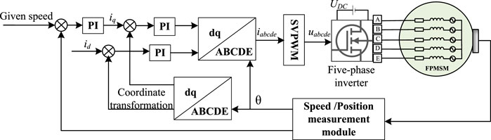
FIGURE 1. Block diagram of motor control system based on FOC.
Mathematical model of five-phase permanent magnet synchronous motor
The basic idea of coordinate transformation is to convert relevant variables into the five-phase static coordinate system to the d-q rotating coordinate system for mathematical operations. The d-q axis is a rotating coordinate system with synchronous rotational speed established by the synchronous rotation of the stator and rotor magnetic fields of the motor during coordinate transformation. The controller changes the voltage of the d-q axis to control the current of the d-q axis. However, in the end, the five-phase voltage of the motor can only be the voltage in the static coordinate system. Therefore, the corresponding inverse transformation must be performed again in the control algorithm, to convert the voltage of the d-q axis into a five-phase voltage for the drive bridge.
For the five-phase PMSM, the design, processing, and installation of permanent magnets will make the air-gap magnetic field become non-ideal sinusoidal, with a certain amount of 3rd harmonic components. In addition, some research works artificially inject the 3rd harmonic magnetic potential to improve the power and torque ripple of the motor (Gao et al. (2013); Chen Q. et al. (2022)). Therefore, there will be a non-zero third harmonic current. It is beneficial to consider both the fundamental current and the third harmonic current in the modeling process for the subsequent work.
where T = TParkTClarke,
The five-phase motor is a coordinate transformation from the natural coordinate system (abcde) to the rotational phase (d1q1d3q3n). This transformation extends the abc → dqn transformation and is used for three-phase to the five-phase case. Usually, the coordinate transformation is divided into two parts: Clarke (abcde to α1β1α3β3z) and Park (α1β1α3β3z to d1q1d3q3n) transformation. Under normal working conditions, the five-phase PMSM extended Clarke transformation matrix is:
In the normal working state of the motor, the Park transformation matrix is:
The stator voltage equation of the five-phase PMSM in natural coordinates is (Tian et al. (2018)):
where Us and Is are the stator voltage and current vectors, respectively. Rs and Ls are the stator resistance and stator inductance matrices, respectively. Λm is the permanent magnet flux linkage vector represented by its first and third space harmonics, as shown in the following Formula 5.
The electromagnetic torque expression for the five-phase PMSM can be found in (Ge et al. (2018)). Due to the space-time decoupling characteristics of the fundamental wave and 3rd harmonic, the fundamental symmetrical current cannot cause torque ripple. Therefore, the electromagnetic motor torque is given by Equation 6 (Tian et al. (2018)) under the normal state of the motor.
where Pp is the number of pole pairs. The contribution of the third harmonic Λ3iq3 to the total torque is about 1% (Tian et al. (2018)). In summary, we can control the torque by adjusting iq1.
Corrected motor model under fault conditions
If a normal motor model is used in the dq axis under a single-phase fault, the remaining four-phase currents are unbalanced and distorted. The back EMF will cause fluctuations in speed and torque. The A-phase open-circuit fault can be taken as an example for analysis. Once the A-phase is opened, the five-phase motor is reduced from a five-dimensional symmetrical system to a four-dimensional asymmetrical system. Equation 7 shows the decoupling transformation modified Clarke matrix (Dwari and Parsa (2011)). The derivation of (7) is based on following steps. First, removing the first column element corresponding to A. Second, removing the elements corresponding to the third row of id3. Third, modifying the elements to make each row orthogonal to each other.
Here, the motor current expression is:
For the faulty motor, the third row is deleted in order to correct the Clarke transformation matrix, resulting in the lack of
The expression form of the stator voltage remains unchanged. Once an open-circuit motor fault occurs in a certain phase of winding, the system dimension decreases. Moreover, the fundamental wave and the third harmonic are no longer decoupled. At this time, the fundamental wave current will interact with the third harmonic magnetic potential to generate torque ripple. The permanent magnet flux linkage can be expressed as:
The electromagnetic torque equation under fault conditions can also be obtained (Tian et al. (2018)):
When an open-circuit fault occurs in the winding, the winding structure of the stator is no longer symmetrical. Now, the circular rotating magnetic field can be reconstructed by adjusting the amplitude and phase of the residual phase current. Hence, the motor torque is smooth before and after the fault. The system reliability is also improved.
It can be seen that the basic torque component in Equation 11 is the same as the basic torque component in Equation 6 for normal operation of the motor. According to Equation 11, the existence of the 3rd harmonic magnetic potential after the fault will cause the 2nd and 4th torque ripples. In many cases, due to the small
Optimizing the reference current with the adjustment factor
Simulation results indicate that the system can realize the minimum torque fluctuation and even undisturbed operation under single-phase conditions with open-circuit fault. First, the coordinate transformation matrix is modified. Then, the reset reference current is obtained under the constraint of instantaneous power balance. FTC is theoretically realized, but the amplitude of the fault-tolerant current obtained in this way is seriously unbalanced. Simulation results also show that the residual phase current fluctuates greatly and even doubles the motor’s rated current. In practical applications, such a reference current will generate high heat for a long time. It is a big hidden danger to permanent magnets and other working parts. It may cause more secondary severe damage to the motor drive system than an open-circuit fault.
For the above problem of large fluctuation range of residual phase current. Using the idea of vector synthesis, the objective function is to minimize the current fluctuation. The torque fluctuation fluctuates within a small allowable range. The phase current balance is used as the constraint condition. Finally, the adjustment factor α is optimized. Figure 2 shows the control block diagram of the control system. In Figure 2, the reference current of the motor without faults and the fault-tolerant reference current under the optimal torque is vector synthesized under the α adjustment factor. Besides, the fault-tolerant reference current is considered. This approach considers the torque ripple under fault and considers the optimal current for motor operation under fault.
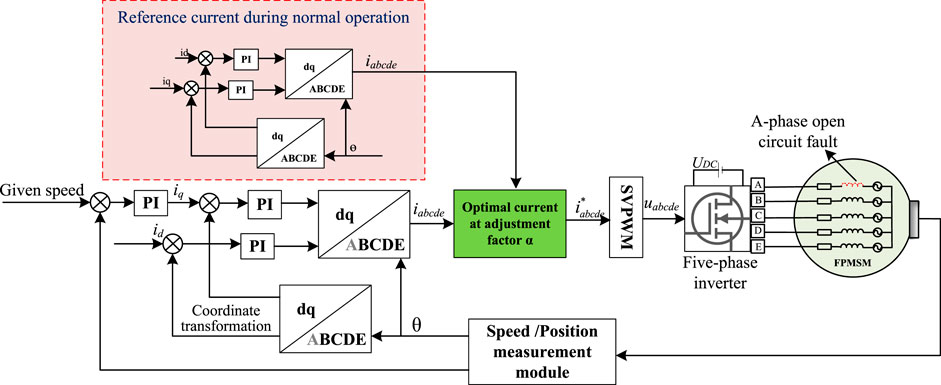
FIGURE 2. Block diagram of system control applying fault-tolerant control strategy.
Chaotic particle swarm optimization algorithm
The chaotic particle swarm optimization (CPSO) algorithm (Wang et al. (2021)) has the following characteristics. The adaptive inertia weight is used to accelerate the convergence speed, which is improved based on the particle swarm optimization (PSO) algorithm. The system is avoided falling into local optimum by performing chaotic searches in the neighborhood. CPSO can be used to solve parameter optimization problems. The traditional PSO algorithm is prone to premature phenomenon in the solution process. To avoid this shortcoming, CPSO was based on a logistic equation. When the particle falls into the local optimum, a chaotic disturbance is used to jump out of the local optimum.
Fault-tolerant reference current of fusion chaotic particle swarm optimization algorithm
The above CPSO is applied to optimize the reference current. The optimization idea of CPSO is followed. Once a fault is detected, the system can smoothly switch from the normal working mode to the fault-tolerant running mode without changing the hardware form. The A-phase open-circuit fault is an example. The reference current is optimized by adding adjustment factors in CPSO. The reference current is divided into the current reference iabcde of the system’s normal operation before the fault and the fault-tolerant reference current
The chaotic particle swarm is used to adaptively optimize α, taking the minimum torque fluctuation as the optimization goal, and the optimal torque state corresponds to an optimal α. The particle swarm variables are:
1) Decision variables α;
2) The minimum torque ripple change is defined as ΔTem, then the objective function is:
The torque fluctuation after fault tolerance is optimized by using the reference current under the fault and the reference current under the normal operation of the motor under the adjustment factor α.
3) Constraints:
In (14), the first equation denotes that the obtained reference current must meet and be zero (Chen Z. et al. (2022)). The second inequality is the electromagnetic torque of the motor is greater than the load torque (Li et al. (2014)). The third inequality denotes that the current fluctuation range is smaller than that without fault tolerance after the fault.
The adjustment factor α is optimized under the above constraints to minimize the torque ripple. This approach considers both the torque fluctuation and the current fluctuation range, which is a dual consideration for the safe operation of the motor. Figure 3 presents the flow chart of alpha optimization.
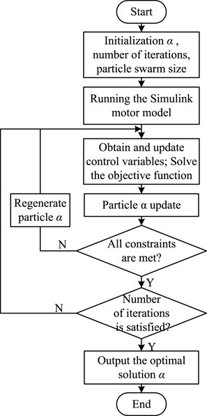
FIGURE 3. Flow chart of chaotic particle swarm optimization α.
Simulation and verification
In order to verify the feasibility of the FT-FOC strategy proposed in this paper, it is used for the normal and single phase open-circuit fault conditions of the motor respectively. Comparisons are carried out with the fault-tolerant reference current based on different adjustment factors α. The five-phase PMSM parameters are shown in Table 1.
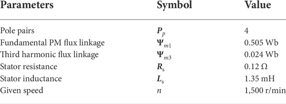
TABLE 1. Parameters of five-phase permanent magnet synchronous motor.
The current, electromagnetic torque and rotational speed curves of the motor under normal and A-phase open-circuit fault states are shown in Figure 4 and Figure 5 respectively.
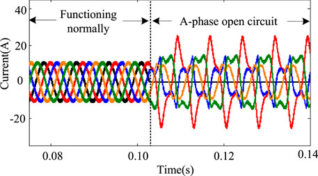
FIGURE 4. Motor current under normal and open-circuit fault conditions.
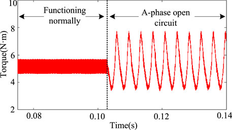
FIGURE 5. Torque of the motor under normal and open-circuit fault conditions.
When the coordinate transformation is used, the current electromagnetic torque waveforms of the motor in the fault and fault-tolerant operation state are shown in Figure 6 and Figure 7, where α = 0.
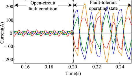
FIGURE 6. Motor current in fault and fault tolerant state.
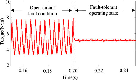
FIGURE 7. Torque in fault and fault tolerant state.
In the normal operation state of the motor, the torque fluctuation range of the motor is 1N ⋅m. After the open-circuit fault of phase A occurs, the torque fluctuation range is 4N ⋅m, which is 4 times that of normal operation. When the fault-tolerant current is used as the reference current, the torque fluctuation range is 0.5N ⋅m, where the optimization effect is remarkable. However, because of the imbalance of the effective value of each phase current, the current fluctuates greatly. The chaotic particle swarm optimization algorithm is used to optimize the current adaptively under the adjustment factor α equal to 0.5 and 0.7, respectively. The simulation results of the current and electromagnetic torque of the motor operation are shown in Figures 8–11.
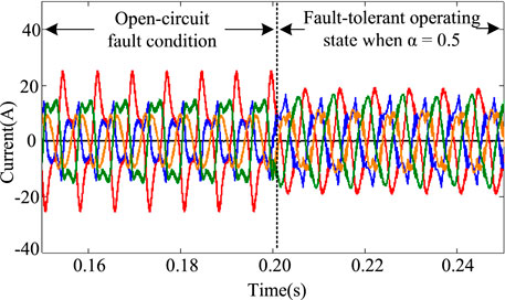
FIGURE 8. Current under the condition of motor fault and FT when α = 0.5.
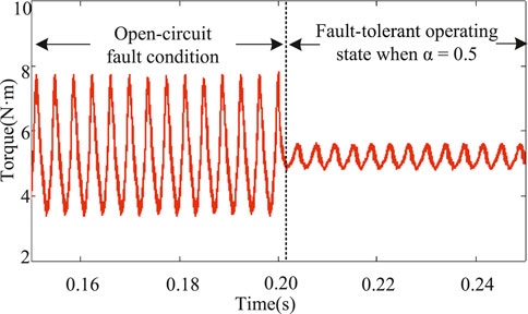
FIGURE 9. Torque under the condition of motor fault and FT when α = 0.5.
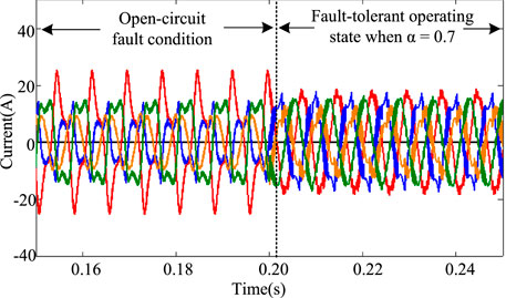
FIGURE 10. Current under the condition of motor fault and FT when α = 0.7.
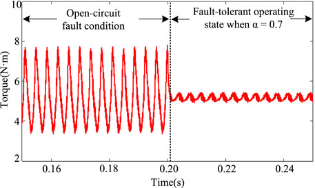
FIGURE 11. Torque under the condition of motor fault and FT when α = 0.7.
In order to further illustrate the current fluctuation of the motor under different adjustment factors, the relationship is obtained between the adjustment factor and the current range from the simulation experiment. The relationship is shown in Table 2.
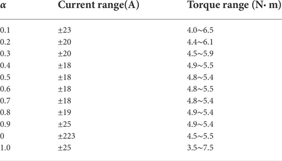
TABLE 2. Relationship between different adjustment factors and current range and torque ripple.
It can be seen from the table that in different applications, the safe operation range of the open-circuit fault and the corresponding torque fluctuation can be selected to meet the safe operation of the motor. Meanwhile, the motor runs reliably and smoothly under acceptable conditions for fluctuations after a fault occurs.
Conclusion
Compared with the previous related research, the main contributions of this paper are as follows. First, the fault-tolerant current is adaptively optimized by the chaotic particle swarm optimization algorithm. The current fluctuation is also considered on the premise of considering the torque fluctuation. The adaptive optimization of the current by the CPSO achieves the effect of filtering and reducing the amplitude of the fault-tolerant current after a fault. From the current point of view, the dimension of the safe operation of the motor is increased. Second, the proposed FT-FOC control strategy has the advantage of maintaining the exact same control structure before and after failure. This ensures a very smooth transition of the system to fault-tolerant mode. Finally, simulation verified that the proposed FTC strategy could reduce the torque pulsation when a fault occurs and ensure that the dynamic performance reaches the normal state level. It can also ensure that the fault-tolerant current range is basically the same as the current range before the fault, which enhances the robustness of the system against external interference.
To sum up, the field-oriented FTC strategy adopted in this paper considers the two motor operating parameters of torque and current simultaneously, which broadens the dimension of reliable operation of the system.
Data availability statement
The original contributions presented in the study are included in the article/Supplementary Material, further inquiries can be directed to the corresponding author.
Author contributions
CC, YS, and YZ contributed to conception and design of the study. JT and SG organized the database. CC and YS performed the simulation and statistical analysis. CC wrote the first draft of the manuscript. YS and BL wrote sections of the manuscript. All authors contributed to manuscript revision, read, and approved the submitted version.
Funding
This work was supported by the Shaanxi Province Key Research and Development Program under Grant (No. 2021GY-149), Shaanxi Province Science and Technology Innovation Guidance Special (Fund) Project under Grant (No. 2022QFY01-16), the National Natural Science Foundation of China (No. 61833013), and the Natural Sciences and Engineering Research Council of Canada.
Conflict of interest
The authors declare that the research was conducted in the absence of any commercial or financial relationships that could be construed as a potential conflict of interest.
Publisher’s note
All claims expressed in this article are solely those of the authors and do not necessarily represent those of their affiliated organizations, or those of the publisher, the editors and the reviewers. Any product that may be evaluated in this article, or claim that may be made by its manufacturer, is not guaranteed or endorsed by the publisher.
References
Chen, F., Hua, W., Huang, W., Zhu, J., and Tong, M. (2019). Open-circuit fault-tolerant strategies for a five-phase flux-switching permanent magnet motor based on model predictive torque control method. Proc. CSEE 39, 337–346. doi:10.13334/j.0258-8013.pcsee.181802
Chen, Q., Xia, Y., Zhao, W., and Liu, G. (2022a). Open-circuit fault-tolerant control for five-phase permanent magnet motors with trapezoidal back-emf by deadbeat current tracking. Trans. China Electrotech. Soc. 37, 368–379. doi:10.19595/j.cnki.1000-6753.tces.200897
Chen, Y., Yang, Z., Zhou, H., Ji, C., and Li, P. (2021). Pmsm open circuit fault tolerance control. Electr. Mach. Control 25, 11–16. doi:10.15938/j.emc.2021.09.002
Chen, Z., Zhang, X., Liu, C., Zhang, H., and Luo, G. (2022b). Research on current decoupling and harmonic suppression strategy of permanent magnet synchronous motor by proportional resonance adaptive disturbance rejection control. Proc. CSEE 1. doi:10.13334/j.0258-8013.pcsee.211791
Dwari, S., and Parsa, L. (2011). Fault-tolerant control of five-phase permanent-magnet motors with trapezoidal back emf. IEEE Trans. Ind. Electron. 58, 476–485. doi:10.1109/TIE.2010.2045322
Fnaiech, M. A., Betin, F., Capolino, G.-A., and Fnaiech, F. (2010). Fuzzy logic and sliding-mode controls applied to six-phase induction machine with open phases. IEEE Trans. Ind. Electron. 57, 354–364. doi:10.1109/TIE.2009.2034285
Gaeta, A., Scelba, G., and Consoli, A. (2013). Modeling and control of three-phase pmsms under open-phase fault. IEEE Trans. Ind. Appl. 49, 74–83. doi:10.1109/TIA.2012.2228614
Gao, H., Yang, G., Liu, J., and Zhao, P. (2013). Air-gap mmf analysis for five-phase pmsm with third harmonic injection. Electr. Mach. Control 17, 1–6. doi:10.15938/j.emc.2013.10.005
Ge, Q., Tian, B., Sun, L., An, Q., and Zhao, K. (2018). Unified foc of five-phase permanent magnet motor under open-circuit conditions. Electr. Power Autom. Equip. 38, 192–200. doi:10.16081/j.issn.1006-6047.2018.02.025
Huang, W., Du, J., Hua, W., and Fan, Q. (2021). An open-circuit fault diagnosis method for pmsm drives using symmetrical and dc components. Chin. J. Electr. Eng. 7, 124–135. doi:10.23919/CJEE.2021.000031
Li, Y., Lu, H., Qu, W., and Sheng, S. (2014). A permanent magnet synchronous motor current suppression method based on resonant controllers. Proc. CSEE 34, 423–430. doi:10.13334/j.0258-8013.pcsee.2014.03.013
Liu, X., Wang, Z., Wang, W., Lv, Y., Yuan, B., Wang, S., et al. (2022). Smo-based sensorless control of a permanent magnet synchronous motor. Front. Energy Res. 10, 1–10. doi:10.3389/fenrg.2022.839329
Liu, X., Zeng, Z., and Wunsch Ii, D. C. (2020). Memristor-based LSTM network with in situ training and its applications. Neural Netw. 40, 300–311. doi:10.1016/j.neunet.2020.07.035
Okedu Kenneth, E., and Barghash, H. (2021). Enhancing the transient state performance of permanent magnet synchronous generator based variable speed wind turbines using power converters excitation parameters. Front. Energy Res. 9, 1–10. doi:10.3389/fenrg.2021.655051
Salehifar, M., Arashloo, R., Moreno-Equilaz, J., Sala, V., and Romeral, L. (2014). Fault detection and fault tolerant operation of a five phase pm motor drive using adaptive model identification approach. IEEE J. Emerg. Sel. Top. Power Electron. 2, 212–223. doi:10.1109/JESTPE.2013.2293518
Tao, T., Zhao, W., Cheng, M., and Wang, Z. (2019). Overview of fault tolerant control and its key technologies for polyphase motors. CJEE 39, 316–326. doi:10.13334/j.0258-8013.pcsee.181589
Tian, B., Mirzaeva, G., An, Q., Sun, L., and Semenov, D. (2018). Fault-tolerant control of a five-phase permanent magnet synchronous motor for industry applications. IEEE Trans. Ind. Appl. 54, 3943–3952. doi:10.1109/tia.2018.2820060
Wang, X., Fu, X., Dong, J., and Jiang, J. (2021). Dynamic modified chaotic particle swarm optimization for radar signal sorting. IEEE Access 9, 88452–88466. –88466doi. doi:10.1109/ACCESS.2021.3091005
Wu, X., Song, W., and Xue, C. (2019). Direct torque control schemes for five-phase permanent magnet synchronous machines based on duty ratio optimization of virtual voltage vector sets. Proc. CSEE 39, 857–867. doi:10.13334/j.0258-8013.pcsee.170953
Zhang, C., Zhao, S., and He, Y. (2021). An integrated method of the future capacity and rul prediction for lithium-ion battery pack. IEEE Trans. Veh. Technol. 71, 2601–2613. doi:10.1109/TVT.2021.3138959
Zhao, S., Zhang, C., and Wang, Y. (2022). Lithium-ion battery capacity and remaining useful life prediction using board learning system and long short-term memory neural network. J. Energy Storage 52, 104901. doi:10.1016/j.est.2022.104901
Zhao, W., Cheng, M., Hua, W., Jia, H., and Cao, R. (2011). Back-emf harmonic analysis and fault-tolerant control of flux-switching permanent-magnet machine with redundancy. IEEE Trans. Ind. Electron. 58, 1926–1935. doi:10.1109/TIE.2010.2050758
Keywords: five-phase permanent magnet synchronous motors, chaos-particle swarm optimization algorithm, open-circuit fault, fault-tolerant control strategy, minimal torque ripple
Citation: Chen C, Song Y, Zhang Y, Tian J, Gao S and Lang B (2022) Adaptive fault-tolerant control of five-phase permanent magnet synchronous motor current using chaotic-particle swarm optimization. Front. Energy Res. 10:994629. doi: 10.3389/fenrg.2022.994629
Received: 15 July 2022; Accepted: 02 August 2022;
Published: 07 September 2022.
Edited by:
Chaolong Zhang, Anqing Normal University, ChinaReviewed by:
Xun Wu, Central South University, ChinaMeng Zhang, Xi’an Jiaotong University, China
Zhao Dongdong, Northwestern Polytechnic University, United States
Copyright © 2022 Chen, Song, Zhang, Tian, Gao and Lang. This is an open-access article distributed under the terms of the Creative Commons Attribution License (CC BY). The use, distribution or reproduction in other forums is permitted, provided the original author(s) and the copyright owner(s) are credited and that the original publication in this journal is cited, in accordance with accepted academic practice. No use, distribution or reproduction is permitted which does not comply with these terms.
*Correspondence: Youmin Zhang, eW16aGFuZ0BlbmNzLmNvbmNvcmRpYS5jYQ==