 Kamal Kant
 Salauddin Ansari
 Om Hari Gupta
- Electrical Engineering Department, National Institute of Technology Jamshedpur, Jamshedpur, India
In order to provide quick and accurate fault detection in a DC microgrid, a new protection strategy is developed in this study. It is based on the multi-resolution analysis of travelling waves. The multi-resolution analysis of travelling waves is carried out using discrete wavelet transform (DWT). The dyadic filter bank theory is used to obtain the DWT coefficient of the voltage travelling wave. The energy of the DWT coefficient is then determined, and the fault will be identified if this energy content exceeds the predetermined threshold value. Initially, the efficacy of the proposed algorithm is verified on a 500 V ring-type bipolar DC microgrid test model, which is developed with MATLAB/Simulink environment. Then the results obtained were later validated with the real-time simulator Opal-RT. The various simulation results indicate that the proposed algorithm can successfully be implemented in both modes, i.e., grid-integrated and islanded. It can also provide protection against high resistance fault (HRF) up to 900 Ω in grid-integrated mode, and up to 1,300 Ω in islanded mode. The operating time of the proposed algorithm is also quite fast, i.e., 0.64 m.
1 Introduction
Due to the global coal crisis and the rising price of crude oil in the global market, many emerging nations must now lessen their reliance on fossil fuels to meet their energy needs (Burke et al., 2018). The inception of renewable energy-based electricity generation and the introduction of an electric transportation system can help a country to become energy independent (Gielen et al., 2019). The introduction of a DC microgrid (DCMG) can also prove to be a crucial breakthrough in the process of electricity generation and utilization. The idea of a DCMG is feasible in the near future due to the significant increase in electronic loads and smart appliances that primarily use DC power (Al-Ismail, 2021).
DC microgrids have several advantages over AC microgrids like low effective resistance, absence of inductive and capacitive reactance, lesser number of power converting stages as compared to AC microgrids, no frequency related issues in DG integration, and many more (Justo et al., 2013). However, the AC microgrid persisted in being preferred over the DC microgrid because of lack of a well-defined standards, technological advancement, and trustworthy protective measures (Joos et al., 2017). The protection of DCMG is one of the challenging issues due to various reasons such as the absence of current-zero crossing points, lack of frequency-dependent parameters, absence of sequence components, quickly rising fault current, etc., (Augustine et al., 2018). As the DC microgrid possesses less physical inertia as compared to the AC system (Sun et al., 2022), hence the fault current in these systems rises rapidly to an intolerant level in a very short duration of time (Beheshtaein et al., 2019). This necessitates the requirement of very fast protection schemes for DC microgrids.
In the past various conventional protection schemes such as over-current protection (Shabani and Mazlumi, 2020), rate of change of current-based protection (Chauhan et al., 2022), differential protection (Dhar et al., 2018), resistance-based protection (Kesava Rao and Jena, 2022), (Yadav and Tummuru, 2020), etc., Have been suggested for the relaying of DC microgrid. Some of the merits of conventional relaying schemes are easy implementation and low computational burden. However, the issues associated with these conventional protection schemes are slow response; high sensitivity for temporary faults; unable to protect against high resistance faults (HRF); And poor selectivity towards temporary faults (Kant and Gupta, 2022). To attain the objective of a faster response, a travelling wave (TW)-based relaying scheme has been proposed in various works of literature. The application of TW-based schemes for the protection of high voltage DC (HVDC) transmission systems has been reported in various kinds of literature. The fact that TW-based schemes do not rely on the magnitude of the fault current is one of their key advantages; as a result, these schemes function satisfactorily against HRFs (Zhang et al., 2012). Although there are various TW-based relaying schemes available for HVDC systems, the application of TW-based protection in low and medium-voltage DC systems (MVDC) is still an unexplored area. In (Saleh et al., 2019), a TW-based relaying strategy has been suggested for an MVDC microgrid. The proposed scheme in this literature is independent of the arrival times of the travelling wave and utilizes waveshape properties of the very first TW initiated by the fault. Due to the requirement of single-ended measurement only, no communication link is required to implement such schemes. Nowadays, many advanced techniques such as wavelet transform (WT), fuzzy logic, artificial neural network (ANN), etc. Are also being applied to improve the performance of the conventional DCMG protection schemes. As discussed in (Sharma et al., 2021), machine learning (ML) techniques are also used in combination with differential protection scheme for quick fault detection. This method uses a ML based support vector machine (SVM) classifier to increase the scheme’s resilience to transient or momentary faults. The problem with this scheme is that it can detect faults up to 10Ω resistance only. In (Mohanty et al., 2021), a cosine similarity-based relaying strategy has been presented for DCMG protection. The operating time of the proposed scheme is 3 m. But again, it can detect faults up to 10Ω resistance only. In (Jayamaha et al., 2019), a WT and ANN-based relaying strategy for a DCMG has been proposed. The proposed scheme can detect the ground fault with a maximum resistance up to 300Ω, but the operating time varies between 3–5.5 m, depending on the type of fault.
Overall, there are a few things, in the available schemes, that may be improved and therefore, in this paper, an advanced short-circuit protection scheme for a DCMG is proposed. The key matters identified with previously discussed methods are a) the operating time of the relay; b) protection against HRFs; c) robustness during external fault or disturbances; and d) the operation during islanded operation. The proposed scheme is developed keeping all these issues into consideration and therefore, the main contributions of the developed scheme are as follows:
• It is an ultra-fast relaying scheme that performs a multi-resolution analysis of TW using the DWT.
• It works successfully under the grid-integrated as well as the islanded mode of DCMG.
• It can successfully detect and classify faults.
• It works effectively for pole-to-pole (PP) and pole-ground (PG) faults for HRFs up to 900 Ω.
• Even in islanded mode, it can successfully detect HRFs up to 1,300 Ω.
• It discriminates between faulty and non-fault conditions such as islanding and load switching events.
• The results obtained are validated using a lab setup with the real-time simulator, i.e., Opal-RT.
The remainder of the paper is structured as follows: Section 2 describes the DC microgrid test system in detail; Section 3 offers a brief explanation on the TW and DWT; Section 4 introduces the suggested algorithm; and Section 5 includes the simulation results and analysis. Section 6 presents the real-time validation of the results, Section 7 presents a comparison of the proposed scheme with the existing schemes, and Section 8 presents the conclusion.
2 DC microgrid test system description
In this study, a 500V ring-main bipolar DCMG architecture, as shown in Figure 1, has been considered for the implementation of the suggested scheme. This test system is a modification of the system considered in (Chauhan et al., 2022). The distributed generation (DG) sources, i.e., PV and battery are connected at bus two through appropriate DC-DC converters. The system is integrated to the grid at bus 1 with the help of a bi-directional voltage source converter (VSC). The bi-directional VSC, connected at the grid interface, enables the power transfer from/to DCMG. When connected to grid, the system voltage is maintained by the grid; and in islanded mode, it is maintained by the local sources. The battery is coupled to the bi-directional DC-DC converter, which is controlled to allow the battery to either absorb or supply power from/to the DC system. The PV-side DC-DC converter is managed to provide the DC system with the maximum real power available. To maintain the positive and negative pole voltage, a voltage balancer circuit is used at each bus. The grounding on the DC side is provided at each bus at the mid-point of voltage balancing capacitors (C1 & C2). A total load of 300 kW (200 kW on bus 3 & 100 kW on bus 1) is connected to the DC system. A detailed description of the components connected to this test system is given in Table 1. The proposed scheme has been implemented for the protection of positive and negative pole lines between bus 1 and bus 2, i.e., lines P12 and N12, respectively. Hence the relays are connected at each terminal of both lines, i.e., RP1, RP2, RN1, and RN2, as shown in Figure 1. Any fault outside this protected zone is considered an external fault.
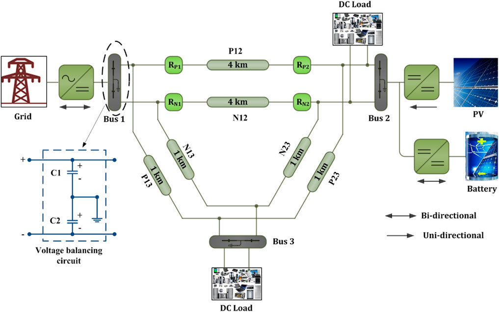
FIGURE 1. Bi-polar DC microgrid test system.
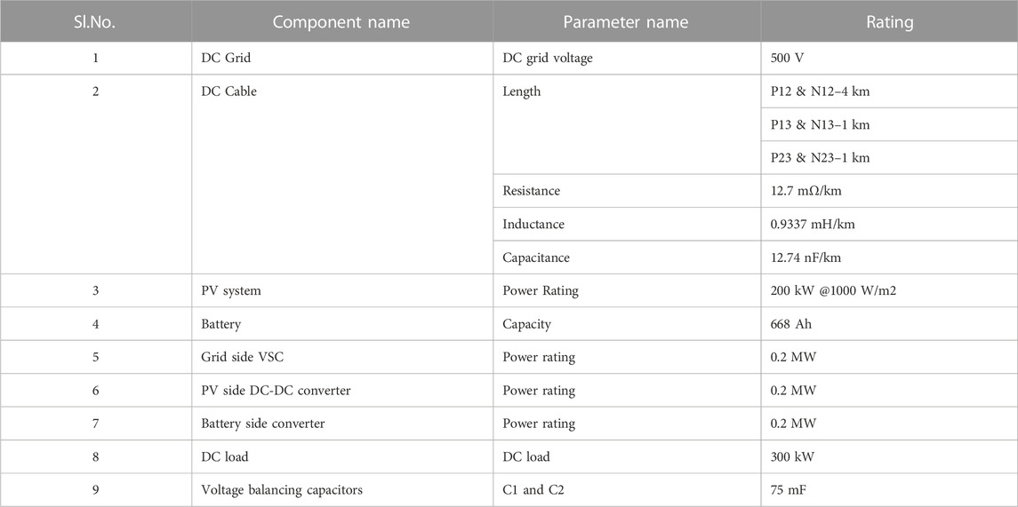
TABLE 1. Detailed description of the DC test system.
3 Preliminaries of TW and DWT
3.1 Travelling wave
Travelling waves (TWs) are electromagnetic transients that are generated at the fault point upon the occurrence of the fault and propagate along the lines at a very high speed, nearly at the speed of light (Aftab et al., 20182020). These propagating TWs are captured at line terminals to design an ultra-fast relaying scheme. The TW-based relaying schemes are not new and widely employed for the protection of high voltage AC (HVAC) and HVDC transmission lines. But the application of these schemes in active distribution networks such as AC or DC microgrids needs to be investigated. The benefits such as ultra-fast operation and the independence of the fault current make the TW-based schemes very suitable for DC microgrid protection.
3.2 Discrete wavelet transform (DWT)
A signal can be processed using the sophisticated mathematical tool known as the wavelet transform (WT) (Pukhova et al., 2017). The WTs can be classified in two categories, viz., continuous wavelet transform (CWT) and discrete wavelet transform (DWT). The scales and locations used by the CWT are unlimited. In contrast, the DWT employs a finite collection of wavelets that have been specified at a specific set of scales and locations. In this study, the DWT has been applied.
Mathematically, the DWT of a signal is given as (Bentley and McDonnell, 1994).
Where f[n] is the input signal, g[n] is the mother wavelet, k is the present sample,
The DWT decomposes the input signal into the detail coefficient (D) and approximation coefficient (A) at each decomposition level. The detail coefficient (D) is the high-frequency component, and the approximation coefficient (A) is the low-frequency component of the input signal (Manohar et al., 2019).
4 Proposed algorithm
The proposed algorithm is developed by combining the concept of TW and DWT. This algorithm does not utilize the timing of the incident wave at the line terminals. Instead, this algorithm is based on the waveshape properties of the travelling waves. The travelling waves were calculated by Eqs 2, 3 (Tiwari et al., 2022).
Where subscript f and b denote the forward and backward wave quantities, respectively. Vtw(k) is the voltage travelling wave at sample k and Zs is the surge impedance of the dc cable. The change in voltage and current at the ith bus can be calculated as in Eqs 4, 5.
The schemes based on the incident time of travelling waves require high frequency transient recorders to capture the travelling waves at the line terminals, and use of such costly equipment is not very economical for distribution lines. Hence in this study, the properties of the travelling are extracted by employing the signal processing tools, i.e., wavelet transform. The first incident forward voltage travelling wave is decomposed into the various high-frequency and low-frequency components by using the DWT’s dyadic filter bank theory, as shown in Figure 2. The selection of the mother wavelet is also an important criterion for the implementation of WT. Some of the literature available (Sabug et al., 20192020) suggest that Daubechies as mother wavelet gives better result in the case of power system studies. The details of the DWT used in this algorithm have been provided in Table 2.
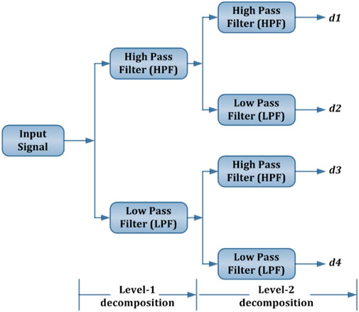
FIGURE 2. Decomposition tree of DWT using dyadic filter bank theory.
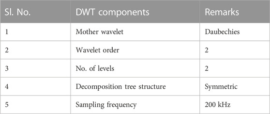
TABLE 2. Details of the DWT used in this algorithm.
The energy content of the extracted DWT coefficients of the voltage travelling wave is calculated by Eq 6.
Where dtw is the high-frequency detail coefficient of the voltage travelling wave (Vtw), and N is the number of samples. In this case, N is taken as 16 samples. The number of samples (N) were decided based on the rigorous simulation studies. The energy content of the DWT coefficient (d3) following a PG fault and PP fault is presented in Table 3.
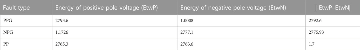
TABLE 3. Energy of travelling wave at positive and negative poles during different types of faults.
If this energy content is more than the pre-set value, then the fault will be detected. The proposed algorithm is also able to classify the faults. With PP fault, the energy content of the DWT coefficient at both positive and negative poles (i.e., EtwP and EtwN) will almost be the same. Hence, the difference between both energies will be very small. If this difference energy is less than the pre-specified value, the fault will be a PP fault. While in the case of PG-fault, this energy difference will be more than the pre-set value. The pre-specified threshold value has been determined by simulating the test model for different fault and non-fault conditions and then observing the energy content of the DWT coefficients in each case. The flow chart of the proposed algorithm is shown in Figure 3.
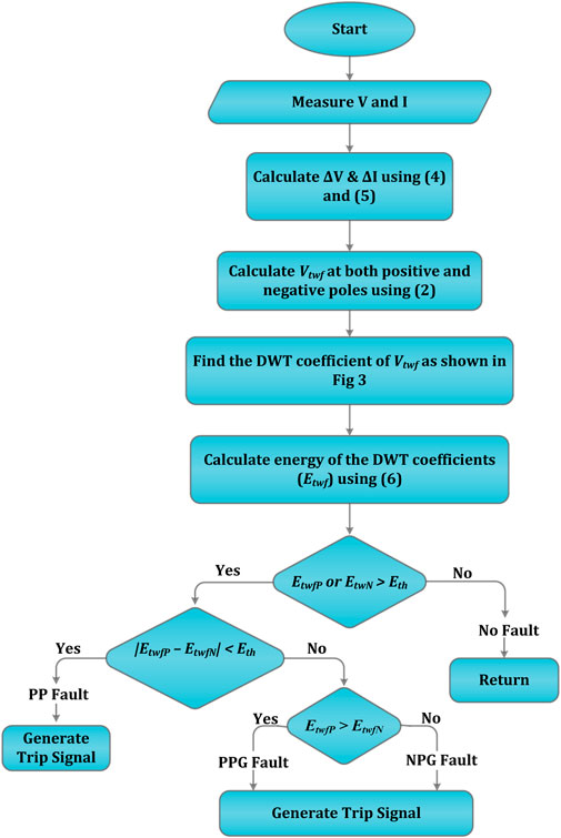
FIGURE 3. Flow chart of the proposed algorithm.
5 Simulation results and discussion
The DCMG test system, as illustrated in Figure 1, is simulated in the MATLAB/SIMULINK environment for the validation of the proposed algorithm. The performance of the suggested algorithm is evaluated in both fault- and non-fault-related scenarios.
5.1 Fault conditions
The performance of the proposed scheme for various fault conditions has been presented in this section.
5.1.1 Pole-to-ground (PG) fault simulation
To investigate the performance of the suggested algorithm for PG-fault, a positive pole-to-ground (PPG) fault with a fault resistance (Rf) of 0.1Ω were simulated on the line P12, and the results have been discussed here. The fault current contribution from the grid (Ifgrid) and DG (Ifdg), and the total fault current (If) following the PPG fault at the mid-point of line P12 are shown in Figure 4. The total fault is equal to the sum of the fault currents supplied from the grid and the DG. As shown in Figure 4, the fault current initially rises to a value greater than 1200 A in very short time duration, i.e., within 15 m, and then quickly settles down to a value around 600 A. For, this test system, normal current in the line P12 is around 55 A. So, the peak fault current is about 22 times the normal line current. That means if the fault current is allowed to reach the peak value, then it can pose some serious damage to the instruments present in the system. Hence, the relaying scheme must clear the fault well before the current reaches its peak value.
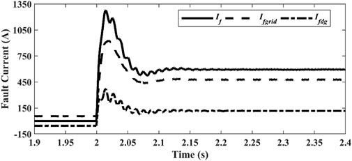
FIGURE 4. Fault current following a PPG fault at t = 2 s.
The energy content of the DWT coefficient of forward voltage travelling wave (EtwfP) is shown in Figure 5A. As soon as this energy content crosses the pre-set value (Eth), the fault is detected, and a trip signal is generated by relays RP1 and RP2 to isolate the faulty line P12. The status of the trip signal from relays RP1 and RP2 is shown in Figure 5B. As shown in Figure 5B, the trip signal becomes high at t = 2.00064 s which means the proposed scheme can detect the PPG fault within 0.64 m, which is quite fast.
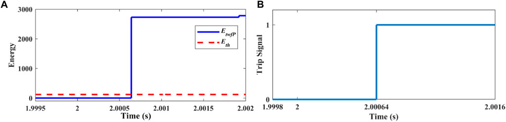
FIGURE 5. (A) Energy of forward voltage travelling wave, (B) Status of trip signal for relays RP1 and RP2 following a PPG fault on line P12 at t = 2 s.
5.1.2 Pole-to-pole (PP) fault simulation
The performance of the proposed algorithm has been evaluated by simulating a pole-to-pole (PP) fault with Rf = 0.1 Ω on the mid-point of the lines P12 and N12. In this case, the forward voltage travelling wave (Vtwf) is calculated at both positive and negative poles. The energy content of the DWT coefficient of the Vtwf is shown in Figure 6. As shown in Figure 6, in the case of a PP fault, the energy of the DWT coefficient at both positive and negative poles is greater than the pre-set value. Hence, in this case, the trip signal will be generated by all four relays (i.e., two positive pole relays RP1 & RP2, and two negative pole relays RN1 & RN2).
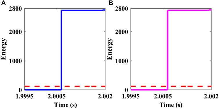
FIGURE 6. Energy content of DWT coefficient Vtwf following a PP-fault at t = 2 s, (A) Energy at the positive pole (EtwfP), (B) Energy at the negative pole (EtwfN).
5.1.3 Protection against HRF fault
In case of an HRF, the post-fault current in the affected line is very close to the pre-fault current in the line. Hence, it is very difficult to detect these types of faults using conventional overcurrent relays. A conventional protection scheme may treat HRF as an overload condition. Hence, an effective protection scheme must be able to distinguish between the fault and the overload case. To examine the operation of the suggested scheme under HRF, a PPG fault with different fault resistance is simulated on the mid-point of line P12. The current in line P12 (Ip12) following a PPG fault with Rf equal to 50 Ω is shown in Figure 7. As the post-fault current in line P12 is very close to the pre-fault current, the current-based protection scheme may not be able to detect this fault. The energy content of the DWT coefficient of the forward voltage travelling wave at the positive pole (EtwfP) following a PPG fault with different fault resistances has been presented in Figure 8. As presented in Figure 8, the proposed algorithm can successfully detect a PG fault of fault resistance up to 900Ω. From Figure 8, it can also be interpreted that the operating time of the proposed algorithm is independent of the fault resistance. The operating time of this algorithm for each fault resistance is 0.64 m.
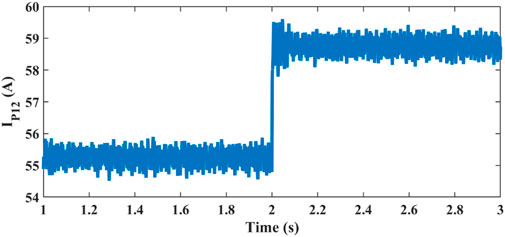
FIGURE 7. Current in line P12 following a PPG fault with Rf = 50 Ω at t = 2 s.
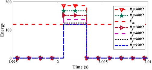
FIGURE 8. Energy content of DWT coefficient following a PPG fault with different fault resistances.
5.1.4 Protection in Islanded mode operation
During islanded mode operation, the power from the grid is not available and the total load connected to the system must be supplied by the DG only. The variation in fault current during islanded and grid-integrated operations can be observed in Figure 9. In islanded operation, the fault current rises rapidly, reaches up to the peak value, and then quickly settles down to an extremely low value as compared to the grid-integrated mode. Hence, a fault in islanded mode must be detected before it settles down to a low value. The performance of the suggested algorithm has been examined by simulating a PPG and PP fault during islanded operation of the DCMG. The fault current following a PPG fault with Rf = 1 Ω during islanded operation is shown in Figure 9. The energy content of the DWT coefficient of Vtwf at the positive pole is shown in Figure 10. As soon as this energy content becomes higher than the threshold energy the trip signal is generated by relay RP1 and RP2.
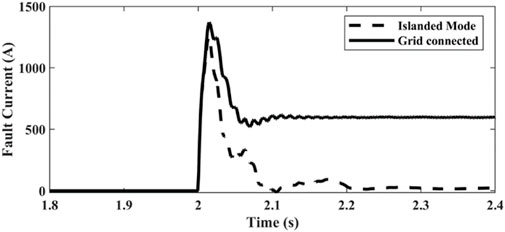
FIGURE 9. Fault current following a PPG fault at t = 2 s in grid-integrated and islanded operation.
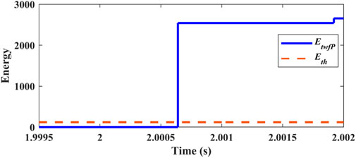
FIGURE 10. Energy of DWT coefficient of Vtwf following a PPG fault with Rf = 1 Ω at t = 2 s during islanded operation of DCMG.
To evaluate the performance against a PP fault, a PP fault with Rf equal to 0.1 Ω is simulated between lines P12 and N12. To generate the trip signal for both positive and negative pole relays, the energy of the DWT coefficient of the Vtwf at both positive and negative poles (i.e., EtwfP and EtwfN) is calculated using Eq 6. In the case of a PP fault, both EtwfP and EtwfN will almost be the same, and in this case, as these values are greater than the pre-set value, as shown in Figure 11, the trip signal will be generated by relays RP1, RP2, RN1, and RN2. To examine the performance of the proposed algorithm against HRF, a PPG fault at line P12 with different fault resistance has been simulated, and the energy of the DWT coefficient of Vtwf is calculated for each case. The simulation results for these cases are presented in Table 4. The data obtained from Table 4 shows that in the islanded mode, the proposed algorithm can protect HRF up to 1,300 Ω.
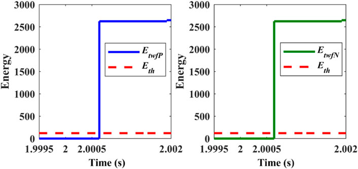
FIGURE 11. Energy of DWT coefficient of Vtwf at both positive and negative pole following a PP fault with Rf = 0.1 Ω at t = 2 s during islanded operation of DCMG.
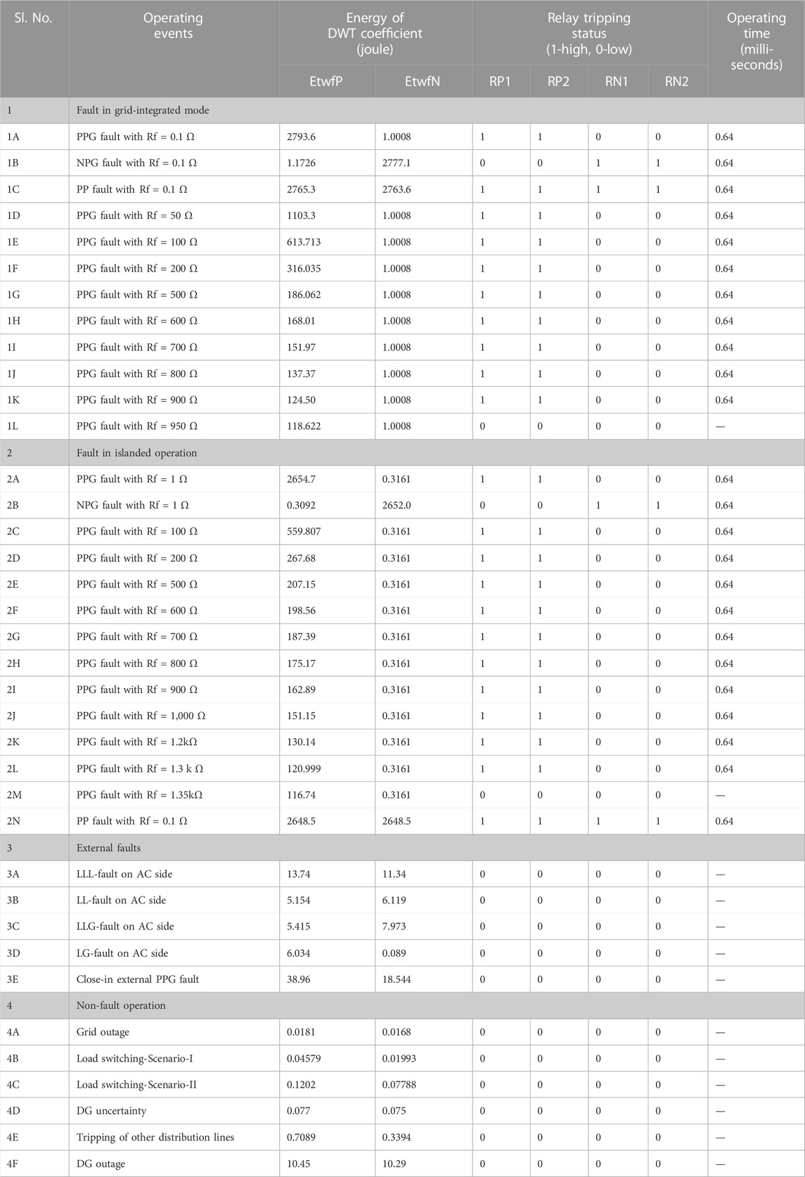
TABLE 4. Summary of the different cases considered in this study for the verification of the proposed algorithm.
5.1.5 Protection during unbalanced loading condition
Till now the utility of the proposed scheme for the balanced network conditions have been presented. In this section, the effectiveness of this scheme during the unbalanced network condition have been presented. To create a unbalance in the system a load of 100 kW is connected at bus-2 between the positive pole and neutral. This load is connected at voltage level of 250 V. The simulation result associated with a PPG fault with Rf = 10 Ω is presented in Figures 12, 13. In balanced condition there will be no current through the neutral during the normal operation. The current in neutral will only if the network is unbalanced, as shown in Figure 12B. The energy of the DWT coefficients presented in Figure 13 confirms the operation of the proposed scheme during the unbalanced loading conditions.
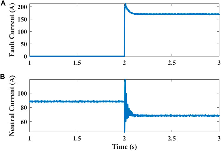
FIGURE 12. Current following a PPG fault with Rf = 10 Ω (A) Fault current (B) Neutral current.
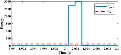
FIGURE 13. Energy of DWT coefficient of Vtwf following a PPG fault with Rf = 10Ω at t = 2 s with unbalanced loading condition.
5.1.6 Impact of noise (SNR 40 dB)
To verify the impact of noise, a noise of SNR 40 dB is added to the current signal measured at relay point RP2. A PPG fault with Rf = 1 Ω is create on the cable P21. The simulation result presented in Figure 14 following this fault confirms that the proposed scheme works successfully under the noisy environment also.
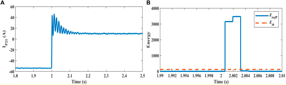
FIGURE 14. (A) Current in cable P21 with SNR 40 dB (B) Energy of Vtwf following the PPG fault.
5.2 External fault condition
5.2.1 AC side fault
A fault on the AC side of the DCMG may also affect the voltage and current on the DC side. But a protection scheme employed for DCMG protection should not respond to these external faults. To demonstrate the effect of AC side faults on the proposed algorithm, an LLL fault on the AC side has been created at t = 2 s. To see the impact of this fault on the status of trip signals for both positive and negative pole relays, the energies of the DWT coefficients of the Vtwf (i.e., EtwfP & EtwfN) are calculated at both positive and negative poles and presented in Figure 15. As shown in the figure, the energies EtwfP and EtwfN are significantly less than the threshold value Eth which is equal to 120. Hence, the trip signal stays low and the protection scheme will not treat this event as a fault.
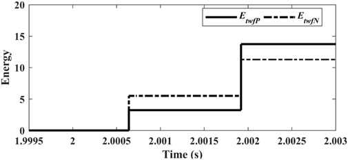
FIGURE 15. Energy content of DWT coefficients of Vtwf at both positive and negative poles following an LLL-fault on the AC side.
5.2.2 External close-in fault
To verify the effect of close-in external fault on the nearby relays, a PPG fault is simulated closer to the relay RP2 outside its protection zone, as shown in Figure 16A.
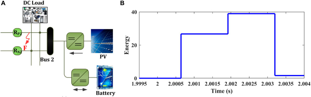
FIGURE16. (A) Close-in external fault; (B) Energy of voltage travelling wave at positive pole following a close-in external PPG fault.
To see the effect of this fault on the tripping status of the relay RP2, the energy of the DWT coefficients of the voltage travelling wave is calculated, and the same has been presented in Figure 16B. As the energy of the DWT coefficient at this point is less than the threshold value, the trip signal for the relay RP2 stays low. It means that the relay RP2 remains unaffected during this external fault.
5.3 Non-fault conditions
A decent protection algorithm needs to be discriminatory enough to distinguish between a fault and a no-fault state. Therefore, several non-fault scenarios such as: grid outage; load switching; DG uncertainty; DG outages; and disconnection of any other distribution line, were simulated and the results have been presented in Table 4. The results presented in Table 4 confirm the selectivity of the proposed approach for non-fault conditions, as this scheme remains unaffected from these non-fault operations.
5.4 Summary
In the previous section, the effectiveness of the proposed algorithm has been verified by implementing this for various fault and non-fault scenarios, and a summary of the same has been presented in Table 4. The proposed algorithm can effectively detect PPG, NPG, and PP faults during both islanded and grid-integrated operations. In grid-integrated mode, it can provide protection against HRF of up to 900 Ω. While during islanded operation, it can detect HRF up to 1,300 Ω. The operating time of the presented scheme is 0.64 m, which is quite fast. In the case of MRA-based schemes, the operating time does not depend on the type of fault and the fault resistances, it mainly depends on the sampling frequency and the no. of samples considered for evaluation. Table 5 shows the effect of sampling frequency and no. of samples on the fault detection time of the proposed scheme. The information presented in the table shows that the proposed scheme works satisfactorily (with slight compromise in fault detection time, i.e., 0.8 m) up to the sampling frequency as low as 10 kHz.
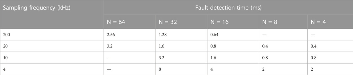
TABLE. 5 Effect of sampling frequency and no. of samples (N) on the fault detection time of the proposed scheme.
6 Real-time validation
The operational validation of the proposed algorithm is conducted with the OPAL-RT time simulator. The laboratory set-up for the real-time validation is shown in Figure 17. The test system shown in Figure 1 is used for real-time simulation. Several cases were simulated for real-time validation of the proposed scheme, and the result of one such case has been presented here.

FIGURE 17. Laboratory set-up for real-time validation of the proposed algorithm.
6.1 Case: PPG fault with Rf = 0.1 Ω in grid-integrated mode
The real-time result of a PPG fault in grid-integrated mode, with Rf = 50 Ω, is shown in Figure 18. As seen in the figure, the wavelet energy (Etwf) increases up on the fault inception, and as soon as this energy becomes greater than the threshold value, the trip signal becomes high. The change in fault current (If) and the variation in positive pole voltage at bus-2 (VB2P) following the PPG fault inception can also be observed in Figure 18.
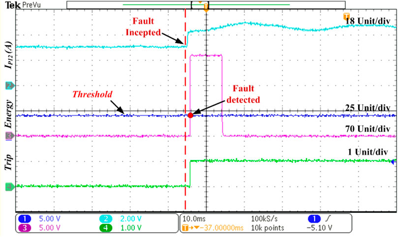
FIGURE 18. Real-time result for PPG fault at the middle of the line P12 with Rf = 50 Ω during the grid-integrated mode.
7 Comparative study
In Table 5, the performance of the suggested algorithm is contrasted with that of other currently available techniques. Table 6 shows that the suggested algorithm can identify a ground fault up to a fault resistance of 900 Ω in the grid-integrated mode, which is greater than the other approaches stated in the literature. The suggested algorithm operates in 0.64 m, which is faster than the majority of the algorithms described in the literature. The suggested system does not malfunction in the presence of an outside disturbance like an AC side fault, a grid outage, or a DG outage. Since it is unaffected by external or non-fault situations, this protection strategy offers superior stability than others. Investigating whether a protection strategy is adaptable enough to function well in both grid-integrated and islanded modes is another crucial situation. This situation has not been taken into account by the numerous protection strategies studied in the literature. However, the efficiency of the suggested algorithm has been carefully examined for both grid-integrated and islanded operations. The study’s findings confirm that the suggested strategy can properly function in both operating modes. Additionally, in islanded mode, it is capable of detecting PG faults up to 1,300 Ω fault resistance. As a result, the suggested scheme proves to be superior to the other existing schemes in many aspects.
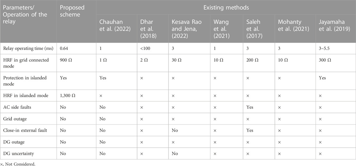
TABLE 6. Comparison of the proposed algorithm with existing methods.
8 Conclusion
For the preservation of DCMG, a novel protection system has been described in this study. In order to verify the effectiveness of the suggested approach, a test model for a 500 V ring-main bipolar DCMG was created in the MATLAB/Simulink environment. Faults such as PPG, NPG, and PP were then simulated. The suggested algorithm has been shown to be a very efficient solution for the protection of DC microgrids and can function well in both grid-integrated and islanded modes. Additionally, it is capable of detecting HRFs of up to 900Ω in grid-integrated mode and 1,300 Ω in islanded mode. The operating time of the proposed algorithm is independent of the type of faults and fault resistances, and it can detect all types of faults in 0.64 m, which is quite fast. The suggested algorithm’s resilience has been tested during faults and external disturbance transients, and it has been discovered that this scheme is unaffected by these external disturbances. The suggested approach is therefore very robust, accurate, and highly selective and offers a quick, stable, and trustworthy solution for the protection of DC microgrids.
Data availability statement
The raw data supporting the conclusion of this article will be made available by the authors, without undue reservation.
Author contributions
KK, SA, and OG has contributed to the conception and design of this work. KK has done the statistical analysis and prepared the first draft of the manuscript. All authors contributed to manuscript revision, read, and approved the submitted version.
Conflict of interest
The authors declare that the research was conducted in the absence of any commercial or financial relationships that could be construed as a potential conflict of interest.
Publisher’s note
All claims expressed in this article are solely those of the authors and do not necessarily represent those of their affiliated organizations, or those of the publisher, the editors and the reviewers. Any product that may be evaluated in this article, or claim that may be made by its manufacturer, is not guaranteed or endorsed by the publisher.
References
Aftab, M. A., Hussain, S. M. S., Ali, I., and Ustun, T. S. (2018). Dynamic protection of power systems with high penetration of renewables: A review of the traveling wave based fault location techniques. Int. J. Electr. Power Energy Syst. 114, 105410. doi:10.1016/j.ijepes.2019.105410
Al-Ismail, F. S. (2021). DC microgrid planning, operation, and control: A comprehensive review. IEEE Access 9, 36154–36172. doi:10.1109/ACCESS.2021.3062840
Augustine, S., Quiroz, J. E., Reno, M. J., and Brahma, S. (2018). “DC microgrid protection: Review and challenges,”. SAND2018-8853 (Albuquerque, NM: Sandia National Laboratories). doi:10.2172/1465634
Beheshtaein, S., Cuzner, R. M., Forouzesh, M., Savaghebi, M., and Guerrero, J. M. (2019). DC microgrid protection: A comprehensive review. IEEE J. Emerg. Sel. Top. Power Electron., 1. in press. doi:10.1109/jestpe.2019.2904588
Bentley, P. M., and McDonnell, J. T. E. (1994). Wavelet transforms: An introduction. Electron. Commun. Eng. J. 6 (4), 175–186. doi:10.1049/ecej:19940401
Burke, P. J., Stern, D. I., and Bruns, S. B. (2018). The impact of electricity on economic development: A macroeconomic perspective. Int. Rev. Environ. Resour. Econ. 12 (1), 85–127. doi:10.1561/101.00000101
Chauhan, P., Gupta, C. P., and Tripathy, M. (2022). A novel adaptive protection technique based on rate-of-rise of Fault Current in DC microgrid. Electr. Power Syst. Res. 207, 107832–107913. doi:10.1016/j.epsr.2022.107832
Dhar, S., Patnaik, R. K., and Dash, P. K. (2018). fault detection and location of photovoltaic based DC microgrid using differential protection strategy. IEEE Trans. Smart Grid 9 (5), 4303–4312. doi:10.1109/TSG.2017.2654267
Gielen, D., Boshell, F., Saygin, D., Bazilian, M. D., Wagner, N., and Gorini, R. (2019). The role of renewable energy in the global energy transformation. Energy Strateg. Rev. 24, 38–50. doi:10.1016/j.esr.2019.01.006
Jayamaha, D. K. J. S., Lidula, N. W. A., and Rajapakse, A. D. (2019). Wavelet-multi resolution analysis based ANN architecture for fault detection and localization in DC microgrids. IEEE Access 7, 145371–145384. doi:10.1109/ACCESS.2019.2945397
Joos, G., Reilly, J., Bower, W., and Neal, R. (2017). The need for standardization: The benefits to the core functions of the microgrid control system. IEEE Power Energy Mag. 15 (4), 32–40. doi:10.1109/MPE.2017.2690518
Justo, J. J., Mwasilu, F., Lee, J., and Jung, J. W. (2013). AC-microgrids versus DC-microgrids with distributed energy resources: A review. Renew. Sustain. Energy Rev. 24, 387–405. doi:10.1016/J.RSER.2013.03.067
Kant, K., and Gupta, O. H. (2022). DC microgrid: A comprehensive review on protection challenges and schemes. IETE Tech. Rev. 210, 1–17. doi:10.1080/02564602.2022.2136271
Kesava Rao, G., and Jena, P. (2022). Unit protection of tapped line DC microgrid. IEEE J. Emerg. Sel. Top. Power Electron. 10 (4), 4680–4689. doi:10.1109/JESTPE.2022.3143525
Manohar, M., Koley, E., and Ghosh, S. (2019). “A wavelet and ANFIS based reliable protection technique for Microgrid,” in Proceedings of the 2019 8th International Conference on Power Systems: Transition towards Sustainable, Smart and Flexible Grids ICPS, 1–6. doi:10.1109/ICPS48983.2019.9067617Jaipur, India December 2019
Mohanty, R., Sahoo, S., Pradhan, A. K., and Blaabjerg, F. (2021). A cosine similarity-based centralized protection scheme for dc microgrids. IEEE J. Emerg. Sel. Top. Power Electron. 9 (5), 5646–5656. doi:10.1109/JESTPE.2021.3060587
Pukhova, V., Gorelova, E., Ferrini, G., and Burnasheva, S. (2017). “Time-frequency representation of signals by wavelet transform,” in Proc. 2017 IEEE Russ. Sect. Young Res. Electr. Electron. Eng. Conf. ElConRus, Moscow, Russia, April. 2017, 715–718. doi:10.1109/EICONRUS.2017.7910658
Sabug, L., Musa, A., Costa, F., and Monti, A. (2019). Real-time boundary wavelet transform-based DC fault protection system for MTDC grids. Int. J. Electr. Power Energy Syst. 115, 105475. doi:10.1016/j.ijepes.2019.105475
Saleh, K. A., Hooshyar, A., and El-Saadany, E. F. (2017). Hybrid passive-overcurrent relay for detection of faults in low-voltage DC grids. IEEE Trans. Smart Grid 8 (3), 1129–1138. doi:10.1109/TSG.2015.2477482
Saleh, K. A., Hooshyar, A., and El-Saadany, E. F. (2019). Ultra-high-speed traveling-wave-based protection scheme for medium-voltage DC microgrids. IEEE Trans. Smart Grid 10 (2), 1440–1451. doi:10.1109/TSG.2017.2767552
Shabani, A., and Mazlumi, K. (2020). Evaluation of a communication-assisted overcurrent protection scheme for photovoltaic-based DC microgrid. IEEE Trans. Smart Grid 11 (1), 429–439. doi:10.1109/TSG.2019.2923769
Sharma, N. K., Saxena, A., and Samantaray, S. R. “An intelligent differential protection scheme for DC microgrid,” in Proceedings of the 2021 9th IEEE International Conference on Power Systems (ICPS), Moscow, Russia, December 2021, 1–6. doi:10.1109/icps52420.2021.9670330
Sun, S., Tang, C., Hailati, G., and Xie, D. (2022). Voltage monitoring based on ANN-aided nonlinear stability analysis for DC microgrids. Front. Energy Res. 1, 1–14. doi:10.3389/FENRG.2022.1045809
Tiwari, R. S., Gupta, O. H., and Sood, V. K. (2022). fault detection using backward propagating traveling waves for bipolar LCC-HVDC lines. Electr. Power Components Syst. 50 (1), 1–14. accepted. doi:10.1080/15325008.2022.2136788
Wang, T., Liang, L., Gurumurthy, S. K., Ponci, F., Monti, A., Yang, Z., et al. (2021). Model-based fault detection and isolation in DC microgrids using optimal observers. IEEE J. Emerg. Sel. Top. Power Electron. 9 (5), 5613–5630. doi:10.1109/JESTPE.2020.3045418
Yadav, N., and Tummuru, N. R. (2020). A real-time resistance based fault detection technique for zonal type low-voltage DC microgrid applications. IEEE Trans. Ind. Appl. 56 (6), 6815–6824. doi:10.1109/TIA.2020.3017564
Keywords: DC microgrid, travelling wave, wavelet transform, high resistance faults, islanded mode protection
Citation: Kant K, Ansari S and Gupta OH (2023) An advanced short-circuit protection scheme for a bipolar DC microgrid. Front. Energy Res. 11:1100789. doi: 10.3389/fenrg.2023.1100789
Received: 17 November 2022; Accepted: 09 January 2023;
Published: 19 January 2023.
Edited by:
Mahamad Nabab Alam, National Institute of Technology Warangal, IndiaReviewed by:
Anu Bhalla, Indian Institute of Technology Roorkee, IndiaHareshkumar Sabhadia, Singapore Institute of Technology, Singapore
Monalisa Biswal, National Institute of Technology Raipur, India
Copyright © 2023 Kant, Ansari and Gupta. This is an open-access article distributed under the terms of the Creative Commons Attribution License (CC BY). The use, distribution or reproduction in other forums is permitted, provided the original author(s) and the copyright owner(s) are credited and that the original publication in this journal is cited, in accordance with accepted academic practice. No use, distribution or reproduction is permitted which does not comply with these terms.
*Correspondence: Kamal Kant, MjAyMXJzZWUwMDRAbml0anNyLmFjLmlu