 Seyyed Mohammad Nobakhti
 Abbas Ketabi
- 1Department of Electrical Engineering, Technical and Vocational University (TVU), Tehran, Iran
- 2Department of Electrical and Computer Engineering, University of Kashan, Kashan, Iran
Microgrid properties including bidirectional power flow in feeders, fault level decrease in the islanded mode, and intermittent nature of distributed generators (DGs) result in the malfunctioning of microgrid conventional protection schemes. In the present article, a protection scheme based on impedance is suggested for fault detection in LV and MV overhead and cable distribution lines in both grid-connected and islanded modes. To determine a fault detection index, new suggested equivalent circuits for doubly fed lines are applied. Relay location data and magnitude of positive sequence voltage of the other end of the line are used. It is simulated by PSCAD and MATLAB software in order to evaluate its performance and approve its validity. This scheme can detect even high-impedance faults in both grid connected and islanded modes in LV and MV overhead and cable distribution lines. In addition, it is robust against load and generation uncertainty and network reconfigurations. Low sampling rate and minimum data exchange are among the advantages of the proposed scheme.
1 Introduction
Microgrids are made of medium- and low-voltage distribution systems including distributed generators (DGs) and loads, capable of operating in islanded and grid-connected modes in an organized and controlled way. Microgrids mainly improve the reliability and resiliency of the power system. An advantage of microgrids is their capability of facilitating more creative schemes to meet local demands flexibly with small-scale generators and consumers closely integrated (Mirsaeidi et al., 2016), (Teimourzadeh et al., 2016).
Regardless of the advantages of microgrids, extensive use of microgrids leads to protection and control challenges and coordination problems with the main network. Because of the presence of looped feeders, bidirectional power flow in the lines, and a considerable decrease in the fault level in the islanded mode, the conventional strategies of microgrid protection do not operate correctly (Blaabjerg et al., 2017).
Furthermore, in traditional distribution networks, if a fault occurs, the recloser disconnects the fault from the utility in a fast mode and reconnects after a short interval. It may cause fault self-clearing if it was temporary. However, in the distribution network with DGs, to ensure the correctness of automatic reclosing, DGs should be entirely disconnected before reconnecting. If during the disconnecting interval, a DG continues its connection to the network, after the short break and utility reconnection, the fault may not be cleared because the DG has fed the arc during the disconnecting interval. In addition, after the break, the frequency changes are probable in the distribution network islanded part. So, by reclosing the switch, two operating systems consisting of active sources with different frequencies on both sides of one recloser are coupled (Jiao et al., 2015), (Adly et al., 2017). Therefore, new communication-based protection schemes with intelligent devices are required to protect these lines (Aminifar et al., 2014).
In general, microgrid protection schemes are configured in two classes: first, network modifying-based schemes modifying the behavior of the grid during the fault for correct performance of traditional protection schemes; second, protective strategy-based schemes modifying conventional protection schemes based on behaviors of microgrids.
A. Network modifying-based schemes
The fault current level changes considerably when the microgrid alters from grid-connected to islanded mode and vice versa. Some protection strategies use external devices for decreasing the main grid fault current contribution. These devices include fault current limiters, ultra-capacitors, flywheels, batteries, and ones installed between the microgrid and the main grid. Mostly, the implementation of these schemes needs high investment (Khederzadeh, 2012; Ghanbari and Farjah, 2013; Esmaeili Dahej et al., 2018).
Grounding strategy modification was suggested in Teimourzadeh et al. (2016) to avoid mal-operation of conventional protection strategies. To some extent, it affords correct operation conditions of relays at a low cost.
In Oureilidis and Demoulias (2016), a scheme was proposed for the protection of looped microgrids with a conventional protection system. The fault was detected by indirectly measuring the impedance of the microgrid. Then, the control system of DGs was adjusted to inject a current proportionate to the measured microgrid impedance, according to a droop curve. This meant that DGs closer to the fault injected a moderately larger current and provided selective coordination of the protection devices.
B. Protective strategy-based schemes
There are several kinds of microgrid protection schemes in this class. Adaptive strategies are one group. In these schemes, relay settings are modified automatically when the operation mode of the microgrid (islanded or grid-connected) is changed (Orji et al., 2017). A scheme for the protection of microgrids in both operation modes applying phasor measurement units (PMUs) on the basis of positive sequence impedance was presented in Mirsaeidi et al. (2016). However, it was required to update the values of pickup relays after a configuration change in the microgrid. In Laaksonen et al., 2014), a monitoring system was explained, in which online updating of the relay settings was based on the operating modes of the microgrid. It used communication links to collect data from smart electronic devices and send data to a central controller for real-time analysis.
One challenge of using these schemes is substituting all the existing relays with adaptive ones, which is costly and requires upgrading the present protection schemes of distribution systems. Moreover, adaptive relays usually need communication infrastructures.
Differential-based schemes as another group compare the currents entering and leaving the protected zone and operate when the differential between these currents exceeds a predetermined magnitude (Zeineldin et al., 2006), (Sortomme et al., 2010). A multi-agent microgrid protection scheme based on a variable tripping time differential protection was suggested by Aghdam et al. (2019) and would be capable of operating in both grid-connected and islanded modes. Moreover, in Kar et al. (2017), the differential features were extracted from the fault current and voltage by applying the discrete Fourier transform, and a decision-tree data mining model was proposed to decide ultimately.
Generally, differential schemes require a communication system and synchronized measurements. Moreover, transients and unbalanced loads may challenge the operation of the protection system.
Another group is voltage-based schemes. Some voltage-based protection schemes recognize the faults by detecting the fundamental voltage-positive sequence component. Some others apply the d–q transform. Loix presented a technique on the basis of the impact of different types of faults on the components of the voltage Park transform for protecting microgrids against different faults (Loix et al., 2009). Differential angle variations of the voltages of buses with the common coupling point voltage were used to propose a scheme for microgrid protection in Sharma and Samantaray (2019). This scheme required synchronous measuring of the angles of several bus voltages. This protection scheme recognized fault occurrence; however, it was not able to determine the faulty line of the microgrid.
Generally, in these schemes, the type of fault and voltage depth magnitude during the fault change the detection time. Hence, these schemes are mainly dependent on the operational mode of the microgrids. Incorrect protections may be triggered by voltage fluctuations owing to non-fault happenings in the islanded mode of microgrids.
In addition, the overcurrent schemes are another group in this class (Best et al., 2009). An overcurrent relay characteristic was proposed in Darabi et al. (2020) to reduce the time of operation of the overcurrent relay. Zero and negative sequence currents were applied for proposing the protection scheme in Zamani et al. (2011). Furthermore, in Furlan et al. (2018), unbalances of voltage were used to improve the overcurrent operation.
Usually, these schemes are highly dependent on wide-area communication systems and are affected by fault level changes.
In distance protection, impedance or admittance is utilized for fault detection. Here, for a fault occurrence downstream of the distance relay location where DGs are installed, the distance relay observes an impedance larger than the actual impedance of the fault. It causes an ostensibly increased distance in the fault because of the added voltage due to an infeed at the common bus. It may lead to a malfunction of the distance relays (Hooshyar and Iravani, 2017). The effects of the resistance of the fault and midway infeed on the performance of the distance protection system in the radial feeders of distribution grids were studied in Nikolaidis et al. (2018). In addition, the combined influence of fault resistance and infeed on the distance protection system was assessed, and resulting problems concerning suitable relay operations were illustrated. In Bottrell and Green (2013), faults were detected by applying the inverse-time tripping admittance. In addition, impedance differential and inverse-time low-impedance protection schemes were proposed in Huang et al. (2014) as the main and backup protection schemes, respectively. Furthermore, in Pandakov and Hoidalen (2017), a compensation scheme to omit errors due to impedances of faults and infeed currents was suggested. Biller and Jaeger (2018) proposed a voltage-free scheme for distance protection compatible with inter-infeed and closed-loop feeders to protect lines in the microgrids. This scheme was based on negative sequence currents measured at the relay location and remained unaffected by negative sequence current suppressing converter-connected DGs and fault resistances. In addition, in FangJia et al. (2019), an improved scheme on the basis of time delay and zero sequence impedance was presented.
The most important advantage of these schemes is their independence of change in the fault current in both microgrid operation modes, but the resistance of the fault and the infeed produced by DGs may cause some errors in the measured impedance. Furthermore, current transients may decrease the measurement precision. Optic fibers can be used for the communication link (Shabani and Mazlumi, 2020), and in long lines, PMUs can be placed on buses (Sharma and Samantaray, 2020) (Garcia et al., 2020).
In Wang et al. (2019), a high-impedance fault detection method based on variational mode decomposition was proposed, where the non-linear characteristics of high-impedance faults were modeled. In addition, in Nobakhti et al. (2021), protection algorithms were proposed for main and backup protection in LV microgrid lines, but their operations have not been studied for high-impedance faults. Moreover, the performance of the schemes was not evaluated in MV microgrids and cable lines.
Therefore, it seems a serious requirement for a protection scheme based on impedance for overhead and cable lines, with the least effect of infeed and impedance of the fault on its operation. In this article, a new impedance-based scheme for microgrid protection in grid-connected and islanded modes is proposed. It has the following features:
• High-impedance fault detection
• Correct performance in overhead and cable lines
• Fault detection capability in LV and MV lines
• Suitable detection time
• Low rate of sampling
• Minimal exchange of data
• Independence from uncertainties of load and generation
• Independence from grid reconfigurations
This article comprises the following sections. Short-circuit fault types and their corresponding equivalent circuits used in the suggested protection scheme are presented in Section 2. In the next section, a new fault detection scheme for microgrids based on impedance is proposed. Section 4 elaborates on the simulation of the proposed strategy in PSCAD and MATLAB software to evaluate its performance. , Section 5 concludes the study.
2 Proposed doubly fed line equivalent circuits during short-circuit faults
Because of the presence of DGs, some distribution lines in microgrids are supplied from two ends. These doubly fed distribution lines are depicted in Figure 1. The sequence equivalent circuits of each type of short-circuit fault are required for studying faults.
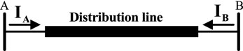
FIGURE 1. Doubly fed distribution line.
In this section, the simplified positive sequence equivalent circuit, abbreviated as “SPS” circuit; simplified negative sequence circuit, abbreviated as “SNS” circuit; and simplified zero sequence circuit, abbreviated as “SZS” circuit, using the conventional sequence ones, are introduced, and they are described in Figure 2, where K is between 0 and 1 and indicates the location of the fault, and “i” may be substituted with “3P,” “LL,” “DLG,” and “SLG” for three-phase, line-to-line, double-line-to-ground, and single-line-to-ground faults, respectively.
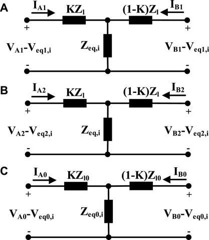
FIGURE 2. (A) SPS, simplified positive sequence circuit; (B) SNS, simplified negative sequence circuit; (C) SZS, simplified zero sequence circuit.
Also, positive, negative, and zero sequence will be symbolized by “1,” “2,” and “0” subscript, respectively. Zl represents positive sequence line impedance, and Zl0 is zero sequence line impedance. Zeq,i and Zeq0,i represent sequence equivalent impedances, and Veq1,i,Veq2,i, and Veq0,i represent sequence equivalent voltages. The sequence equivalent impedances and voltages will be explicated for each fault type distinctively.
A.Three-phase fault
Here, three phases are grounded by resistance Rf. Figure 3 depicts the conventional equivalent circuit that contains the positive sequence. By comparing this figure and the SPS circuit in Figure 2A, Veq1,3P and Zeq,3P are obtained as follows:
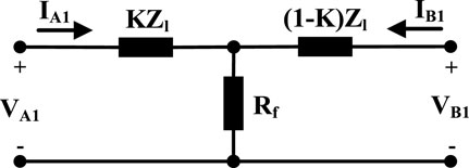
FIGURE 3. SPS circuit for three-phase fault.
There are no SNS and SZS circuits in this fault type because of the absence of negative and zero sequence components.
B. Line-to-line fault
In the line-to-line fault, two phases are connected by resistant Rf. Figure 4 shows the conventional equivalent circuit for this fault comprising the positive and negative sequences.

FIGURE 4. Conventional sequence equivalent circuits for line-to-line fault.
If Thevenin equivalent circuits [VA2 series with impedance KZl and also VB2 series with impedance (1−K)Zl] convert to the corresponding Norton equivalent, after simplifying the resulting circuit, Figure 5A will be attained, where
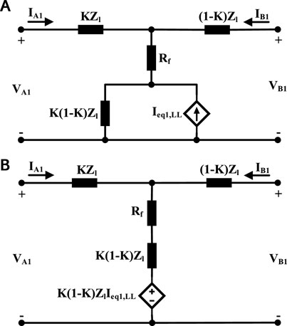
FIGURE 5. Simplified circuit for line-to-line fault. (A) simplified circuit of Figure 4 for line-to-line fault. (B) simplified circuit of Figure 5A.
By altering the dependent current source parallel with impedance (Norton equivalent) to the corresponding dependent voltage source series with impedance (Thevenin equivalent) shown in Figure 5A, the circuit in Figure 5B is obtained. By subtracting voltage K(1−K)ZlIeq1,LL from the voltages of both ends of the circuit, the dependent source in the middle branch is removed. So, the SPS circuit for this fault type is achieved. Veq1,LL and Zeq,LL are obtained as follows:
In the same way, the SNS circuit is achieved, in which
It is clear that there is no SZS circuit for the LL fault.
C. Single-line-to-ground fault
In this fault type, one of three phases is connected to the ground by resistant Rf. Figure 6 shows the sequence equivalent circuits of the single-line-to-ground fault. By simplifying the negative and zero sequence circuits, the SPS circuit is achieved. Similarly, SNS and SZS circuits are achieved:
D. Double-line-to-ground fault
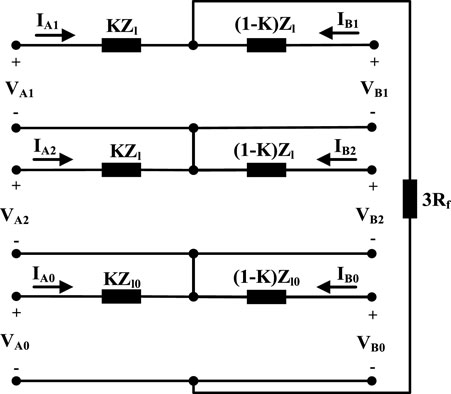
FIGURE 6. Conventional sequence equivalent circuits for single-line-to-ground fault.
This fault will happen when two phases are connected together by resistant Rf and also to the ground by the same resistance. Figure 7 displays the sequence equivalent circuits of the double-line-to-ground fault. Parameters of SNS, SPS, and SZS equivalent circuits will be determined as follows:
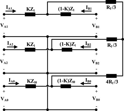
FIGURE 7. Conventional sequence equivalent circuits for double-line-to-ground fault.
where M and N are achieved as follows:
3 Proposed impedance-based protection scheme
Using Y-Δ transform, SPS and SNS circuits shown in Figure 2 are reformed to Figure 8, as follows:
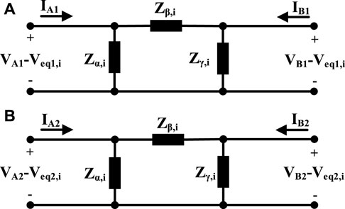
FIGURE 8. Transformed to equivalent delta circuits (A) SPS and (B) SNS.
Based on Eq. 8, by increasing Rf, the absolute value of Zα,LL shall be increased. Rf is infinite under normal conditions, so the absolute value of Zα,LL will be infinite, too, and its angle will be 0. However, during the fault, its absolute value will be decreased drastically and its angle will be increased at most about the angle of the positive sequence impedance of the line. Notably, the line impedance angle in distribution lines is small.
In addition, based on Eq. 9), under normal conditions, the absolute values and angles of impedance Zβ,LL and impedance Zl will be equal, and during the faults, the angle variations of impedance Zβ,LL will be low. The absolute value variations of Zβ,LL will be low, too, except for small Rf. The intensive reduction of Zα,i during the fault can be a basis for fault detection.
Using KCL and KVL in circuits shown in Figure 8 and the SZS circuit, and substituting Rf and K with Zα,i and Zβ,i, the absolute value of VB1 is obtained. If this value equals its sent value from the other line end, and Zβ,i is substituted with Zl (as its value in normal conditions), an equation with variable Zα,i shall be attained.
For example, for the line-to-line fault, KCL leads to
Considering Eq. 8 and Eq. 9, K and Rf can be attained from the following equations:
By substituting calculated K and Rf in the KCL equations and also substituting Zβ,LL with Zl, VB1 is achieved as follows:
In the same way, VB1 is achieved for other faults. By supposing 0 for the angle of Zα,i, two answers will be found for Zα,i (as a real number). One of them has an ineligible negative value. The other answer, for the external faults and normal conditions, is +∞, and during the faults, it decreases to a positive value. So, considering this change, Fault Detection Index (FDIi) can be described as follows:
Constant coefficient Ci is determined, which is slightly greater than the absolute value of Zα,i, for the fault near to the end B with considered maximum fault resistance.
FDIi is negative under normal conditions and may transiently become positive for faults in the adjacent lines. Therefore, consecutive M positive samples of FDIi will detect a fault.
In this scheme, the voltage and current of the line beginning and the positive sequence voltage absolute value of the line end are applied to line protection from the beginning of the line. Thus, only one quantity should be sent from the other side of the line, unlike the previously presented protection schemes, like Huang et al. (2014), that generally required the transmission of two quantities (absolute value and angle of a phasor quantity) or more. Hence, in the proposed scheme, the exchange of data decreases by 50%, which is an advantage. Figure 9 shows the flowchart of this scheme. Nowadays, intelligent digital relays are used extensively, and implementation of the proposed scheme is possible using them.
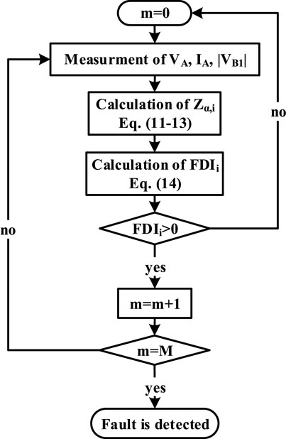
FIGURE 9. Proposed scheme flowchart.
In this scheme, distribution lines were modeled by resistance and inductance, and the line capacitance was ignored. This assumption is acceptable in the overhead lines, but it may be challenged for cable lines in high-resistance faults. In order to modify this scheme for cable lines, the π model of the line is applied (illustrated in Figure 10). So, IA1, IA2, and IA0 in the proposed scheme should be substituted as follows:
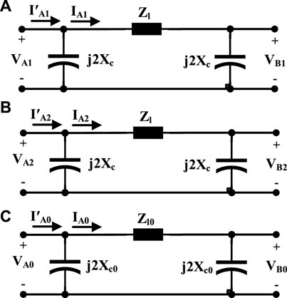
FIGURE 10. π model of the line. (A) positive sequence (B) negative sequence (C) zero sequence.
where Xc is the positive and negative sequence capacitive reactance of the line, and Xc0 is zero sequence capacitive reactance. In addition, I′A1, I′A2, and I′A0 are positive, negative, and zero sequence input line currents, respectively.
4 Case study
A 50-Hz distribution network shown in Figure 11 was simulated in PSCAD and MATLAB software to evaluate the proposed scheme (Huang et al., 2014). Two 400-V and 10-kV networks are connected to the main grid (35 kV) by a transformer. In the coupling point with the main grid, the fault level and R/X ratio are 500 MV A and 0.1, respectively. There are three inverter-based DGs in the 400-V feeders. DG1 and DG2 have nominal powers of 200 kV A and 100 kV A, respectively. DG3 is a photovoltaic system with a nominal power of 50 kV A.
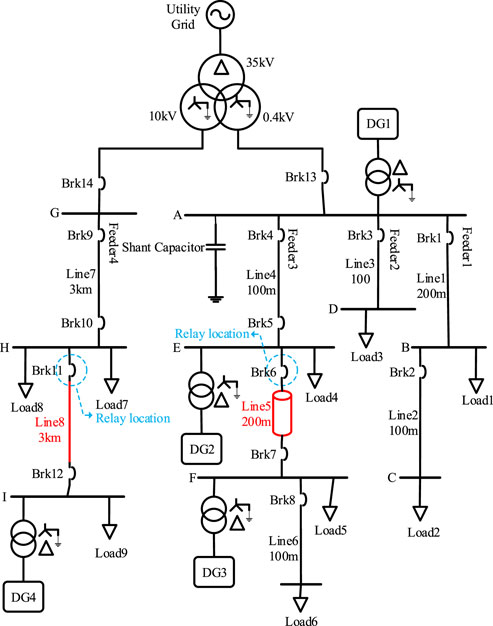
FIGURE 11. Case study system.
The positive and negative sequence resistance of 400-V overhead lines (Lines 1 to 4 and Line 6) is 0.32 Ω/km, and this parameter in the cable line (Line 5) is 0.30 Ω/km. Zero sequence resistances of these overhead lines and the cable line are 1.1 Ω/km and 1 Ω/km, respectively. Moreover, the positive and negative sequence inductance of 400-V overhead lines and the cable line is 0.261 mH/km and 0.223 mH/km, respectively. Zero sequence inductances of these overhead lines and the cable line are 0.955 mH/km and 0.828 mH/km, respectively. In addition, the positive and negative sequence capacitance of the 400 V cable line is 0.07 μF/km, and the zero sequence capacitance is 0.02 μF/km. The nominal reactive power of the shunt capacitor in bus A is 20 kVAr. Load 1, Load 3, and Load 4 have a power of 40 kV A, and the powers of Load 2, Load 5, and Load 6 are 20, 5, and 25 kV A, respectively. The power factor of all loads in 400-V feeders is considered 0.9 lag.
The positive and negative sequence resistance of the 10-kV lines is 0.38 Ω/km, and the zero sequence resistance is 0.76 Ω/km. In addition, the positive and negative sequence inductance of these lines is 1.432 mH/km, and the zero sequence inductance is 4.2 mH/km. The nominal power of DG4 (inverter-based) at the end of the 10-kV feeder is 600 kV A. The power of Load 7 is 100 kV A, and the powers of Load 8 and Load 9 are 500 kV A. The power factor of loads in the 10-kV feeder is considered 0.85 lag.
A 400-V subsystem may be considered a microgrid that can operate in grid-connected or islanded operation mode. In this paper, the control system of DG1, DG2, and DG4 changes from active–reactive power (P–Q) to voltage–frequency (v-f) to support voltage and frequency in the islanded mode, but because of the nature of the photovoltaic system, DG2 retains P–Q control, irrespective of operation modes. The considered equivalent circuit for DGs is shown in Figure 12, which includes dependent voltage sources and inductors as filters.
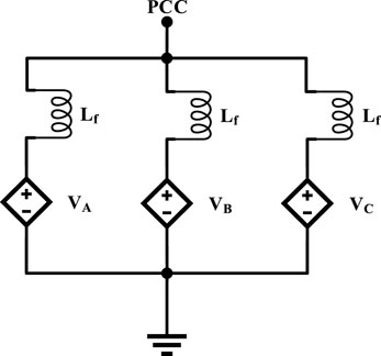
FIGURE 12. Equivalent circuit for DGs.
When the microgrid is in the grid-connected mode, DGs operate in P–Q control mode. In this mode, the DG control system operates so that DG injects active power (Pref) equal to its nominal power and reactive power (Qref) of 0 to the grid. However, when the microgrid operates in the islanded mode, the DGs (except PV) operate in a v–f control mode. In this mode, the DG control system operates for maintaining the voltage and angular frequency of the grid at or near the nominal values (Vrated and ωs). To share the power between DGs according to their nominal powers, the drop control method is applied. The considered DG control system in the grid-connected mode is shown in Figure 13A. In this figure, Vm,rated is the nominal voltage amplitude, ωs is the nominal angular frequency, and t is time. In addition, the considered DG control system in the islanded mode is shown in Figure 13B, where m is the ratio of permissible angular frequency drop to DG rated power, n is the ratio of permissible rated DG drop to rated power and, Vmeas is the measured terminal voltage. It should be mentioned that the output currents of DGs during the fault condition are limited to 1.5 times of nominal currents.
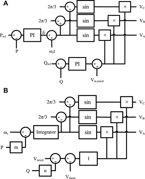
FIGURE 13. DG control system in (A) grid-connected mode and (B) islanded mode.
Optic fibers can be used for the communication link in the proposed scheme. Generally, total communication delay includes four components: transmission delay, queuing delay, propagation delay, and processing delay. Transmission and queuing delays are insignificant for advanced communication systems such as optic fiber with high bandwidth. The delay is around 0.1 ms with a bandwidth of 100–1,000 Mb/s. The propagation delay is small for LV systems with short lines (several µs) (Shabani and Mazlumi, 2020). The processing delay can be minimized using advanced routing. So, the total communication delay will be small enough to enable the data of the absolute value of positive sequence voltage to be transferred between the relays within a timescale <1 ms. For longer lines, PMUs can be located on the buses in IEEE C37.118.1 standard complied extended Kalman filter (EKF) algorithm-based PMUs. PMUs are classified into two types: class P and class M. Class P EKF-based PMUs have faster response times and are suitable for protection applications (Sharma and Samantaray, 2020), (Garcia et al., 2020).
To evaluate the performance of the proposed scheme in the presence of non-linear characteristics of high-impedance faults, the model in Figure 14 was applied (Wang et al., 2019). This model includes two DC sources, Vp and Vn, and corresponding diodes Dp and Dn to form positive and negative half cycle current paths. The two DC sources Vp and Vn simulate the voltage from the arc and are varied randomly and independently. When the instantaneous value vph is greater than Vp, current flows toward the ground and reverses when the instantaneous value vph is lower than –Vn. During –Vn < vph < Vp, no current flows. Changing the value of Vp and Vn increases the randomness and arc suppression time of the asymmetric fault. To simulate the arc resistance that causes the asymmetrical current, Rp and Rn take different values and change randomly and independently.
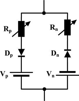
FIGURE 14. High-impedance fault model.
In order to assess the proposed protection scheme, various fault types at Line 5 (cable line) were examined. In addition, faults at Lines 4 and 6 were studied for external faults. The frequency of sampling was considered 200 Hz, and the fault was initiated at t = 10 s.
Considering fault location K = 0.9 and fault resistance Rf = 50 Ω in Eqs 1, 3, 5, and 6, the values of Zeq,3P, Zeq,LL, Zeq,SLG, and Zeq,DLG were obtained. If these values were substituted in Eq. 8 and their absolute values were calculated, then the values of |Zα,3P|, |Zα,LL|, |Zα,SLG|, and |Zα,DLG| are 500, 500, 1,500, and 300, respectively. To ensure proper operation, Ci should be considered 15% greater than these values. Therefore, C3P, CLL, CSLG, and CDLG were considered 575, 575, 1,725, and 345, respectively.
5 Evaluation of the proposed scheme
FDI3P curves for a 3P fault at 50% of line 5 and 10% of line 6 with a resistance 0.01 Ω in the grid-connected operation mode are shown in Figure 15. For a fault inside the protection zone (at Line 5), FDI3P increases rapidly and holds a positive value. However, for a fault outside the protection zone (at 10% of Line 6), it increases transiently and decreases quickly. By studying different fault types at different locations, M (number of positive FDIi to detect fault) was determined 6.
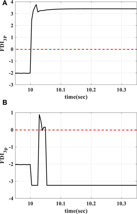
FIGURE 15. FDI3P curve for 3P fault in grid-connected operation mode with fault resistance 0.01 ohm at (A) 50% of Line 5 (constantly positive) and (B) 10% of Line 6 (temporary positive).
Tables 1–4 show FDIi values and the proposed scheme response time for the relay at the beginning of Line 5. The fault resistance was considered 0.01–50 Ω. The results show, if a fault occurs at Line 5 (inside the protection zone), FDIi is positive continually. So, after six sequential positive sample trips, a command will be generated for Brk6. In addition, if a fault occurs at the adjacent lines (outside the protection zone), FDIi holds the negative value (similar to normal conditions) or becomes temporarily positive, so the trip command will not be created. This indicates the stability of the proposed scheme during the faults on the adjacent lines and load changes. Nevertheless, the performance of the proposed scheme was evaluated for connecting a load of 40 kV A with a power factor of 0.9 lag to buses E and F at t = 10 s in grid-connected and islanded modes, and the results confirmed the correct performance of the proposed scheme.

TABLE 1. Proposed scheme performance for three-phase faults.

TABLE 2. Proposed scheme performance for double-line-to-ground faults.
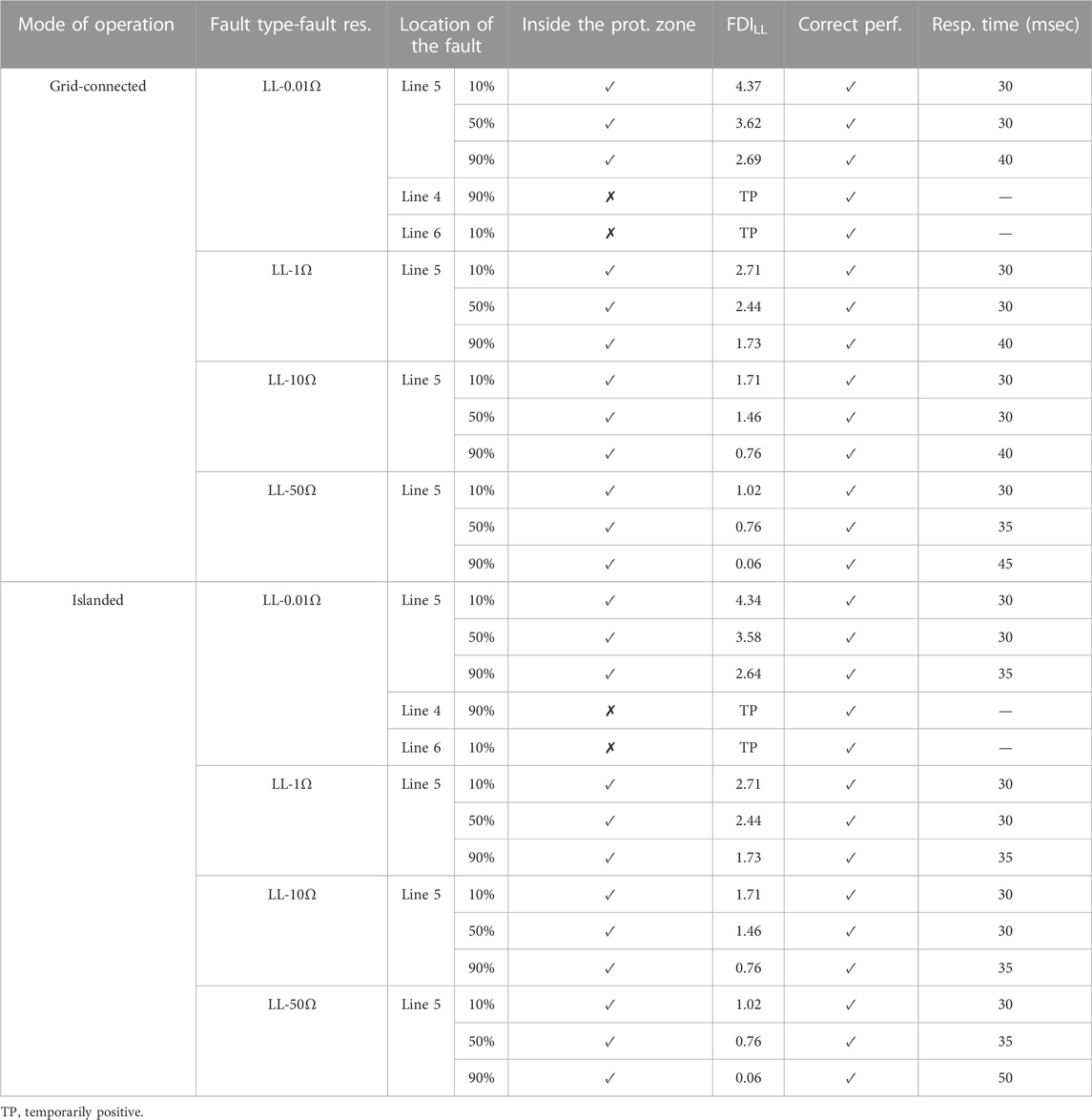
TABLE 3. Proposed scheme performance for line-to-line faults.

TABLE 4. Proposed scheme performance for single-line-to-ground faults.
Moreover, these evaluations were repeated for this network with constant impedance loads, and similar results were obtained. In the same way, this protection scheme is implemented for Brk7 at the end of Line 5. Hence, Brk6 and Brk7 will protect Line 5.
The performance of this scheme was also evaluated for all fault types on overhead Line 4, and the results show the correct performance of the proposed scheme.
In contrast to the transmission system, in distribution lines, due to their short length, noise pollution of the data during the transmission is infrequent, and usually, it is not considered. In addition, because of the short length of distribution lines, determination of fault location does not work.
Generally, in the short circuit fault studies, because the fault current is high, the pre-fault currents of the lines and fault inception time are not so important. However, in high-resistance fault studies, the fault current is not high in comparison to the currents of loads of the network. So, load currents and fault inception time may affect the operation of the protection system. To study the effect of pre-fault conditions on the high-resistance fault detection of the proposed scheme, new pre-fault conditions were discussed. In this case, DG3 was turned off, load 1 to load 6 were doubled, and the fault was initiated at 10.005 s (voltage angle was
So far, for simplicity, the faults have been modeled by net resistance, and the non-linear properties of the high-impedance faults have been ignored. However, to evaluate the performance of the proposed scheme in the high-impedance faults with non-linear properties (Figure 14), Vp was considered to be varied between 150 V and 170 V and Vn between 145 and 155 V randomly and independently every 0.1 ms. In addition, Rp and Rn were considered to take different values between 15 and 25 Ω and change randomly and independently every 0.1 ms. Based on the simulation results, the proposed scheme operated correctly in the high-impedance SLG and LL faults at different points of the line in both operation modes. Accordingly, the non-linear properties of high-impedance faults did not affect the performance of the proposed scheme. The performance of the proposed scheme for pre-fault condition variation and high-impedance faults is shown in Table 5.
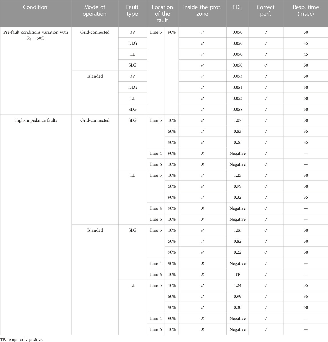
TABLE 5. Performance of the proposed scheme for pre-fault condition variation and high-impedance faults.
Considering that the proposed scheme can detect high-impedance faults, the accuracy of the line parameter value affects its performance significantly. To evaluate this effect, the presence of −5% to +5% error in the considered values for line parameters was studied. The results showed that the proposed scheme does not perform correctly for errors of −5% to −1.5% in the line parameters. In addition, for −1.5% to 0% errors, the proposed scheme can detect faults along the line without any effect, up to 50 Ω fault resistance. For the positive errors, the fault detection capability is limited to the maximum fault resistance shown in Figure 16.
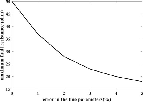
FIGURE 16. Maximum fault resistance for fault detection in the presence of line parameter errors.
So, the proposed scheme detects all fault types in both operation modes of the microgrid. In addition, according to the results of the investigations, this scheme detects faults in a timeline between 30 and 50 ms, and its average response time is 32.8 ms, which is approximately 34% faster than that of the conventional schemes with a response time of approximately 50 ms.
Furthermore, in order to assess the performance of the proposed scheme in the MV lines, all fault types with different resistances are studied at Line 8. The results for line-to-line and single-line-to-ground faults are illustrated in Tables 6, 7. Evaluations for two other fault types also yielded similar results. Considering the results for all fault types, this scheme detects faults correctly in MV lines too. However, in MV lines, response time is between 30 and 80 ms, and the average response time is 35.9 ms.

TABLE 6. proposed scheme for line-to-line faults in the MV line.
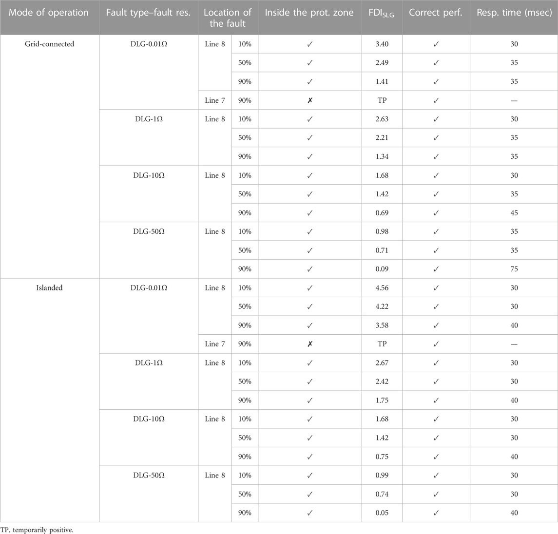
TABLE 7. proposed scheme for single-line-to-ground faults in the MV line.
So, the proposed scheme has advantages compared to the one in Huang et al. (2014). Three subroutines were introduced for detecting solid and low-, medium-, and high-impedance faults in Huang et al. (2014); so, its implementation was complex. However, the proposed scheme detects all faults by the same routine.
In addition, in Huang et al. (2014), the impedance calculated at the end of the line including the absolute value and angle (two quantities) should be sent to the beginning of the line. However, in the proposed scheme, only the absolute value of the positive sequence voltage (one quantity) is sent. This means at least a 50% reduction in data exchange. In addition, the low sampling frequency (200 Hz) is one of the advantages of this scheme compared to that of Huang et al. (2014), with a sampling frequency of 1,200 Hz. So, the lower data exchange leads to more free-up of the communication system for other applications in the microgrid.
Furthermore, one of the properties of the proposed protection scheme is the drastic reduction of Zα,i during the faults compared to under normal conditions. This significantly simplifies the determination of the threshold value of FDIi and is an advantage of the proposed scheme compared to that of Huang et al. (2014). The threshold value in Huang et al. (2014) should have been taken close to the line impedance, which was a small value in short distribution lines, and it could challenge the threshold determination.
In addition, in the evaluation of the proposed scheme, overhead and cable lines were studied in LV and MV networks, while evaluations of the main protection scheme in Huang et al. (2014) were conducted only on the LV overhead lines. Table 8 shows these differences.
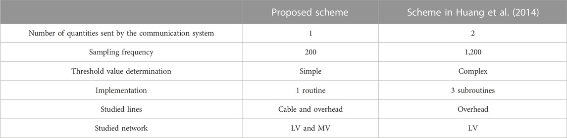
TABLE 8. Comparison of the proposed scheme and the introduced scheme in Huang et al. (2014).
6 Conclusion
In this article, in order to model short-circuit faults in active distribution networks, new equivalent circuits, including SPS, SNS, and SZS, were proposed by reforming conventional sequence equivalent circuits. Then, equivalent delta circuits of these proposed circuits were achieved using star to delta transformation. A significant change in one of the impedances in these delta circuits was the foundation of the proposed protection scheme for microgrids.
In this scheme, the FDIn index was introduced, which can detect the faults in both grid-connected and islanded modes at LV and MV distribution lines. In addition, the proposed scheme was capable of operating correctly in both overhead and cable lines. Considering its average response time, its performance was relatively fast. Releasing at least 50% of the communications system and the low sampling rate of the measurement were advantages of this scheme. In addition, the possibility of high-impedance fault detection, robustness against network reconfigurations, and load and generation uncertainties were capabilities of the proposed scheme. Additionally, infeed and transient situations did not affect the correct performance of the proposed scheme. It was evaluated by simulating in PSCAD and MATLAB software, and the results confirmed its precision.
Data availability statement
The original contributions presented in the study are included in the article/Supplementary Material; further inquiries can be directed to the corresponding author.
Author contributions
SN: conceptualization; formal analysis; investigation; methodology; project administration; software; supervision; validation; writing—original draft; writing—review and editing. AK: conceptualization; investigation; methodology; project administration; supervision; validation; writing—review and editing.
Conflict of interest
The authors declare that the research was conducted in the absence of any commercial or financial relationships that could be construed as a potential conflict of interest.
Publisher’s note
All claims expressed in this article are solely those of the authors and do not necessarily represent those of their affiliated organizations, or those of the publisher, the editors, and the reviewers. Any product that may be evaluated in this article, or claim that may be made by its manufacturer, is not guaranteed or endorsed by the publisher.
References
Adly, A. R., El Sehiemy, R. A., and Abdelaziz, A. Y. (2017). “Optimal reclosing time to improve transient stability in distribution system,” in Cired - open access proc (Journal), 2017, 1359–1362.1
Aghdam, T. S., Kazemi Karegar, H., and Zeineldin, H. H. (2019). Variable tripping time differential protection for microgrids considering DG stability. IEEE Trans. Smart Grid 10 (3), 2407–2415. doi:10.1109/tsg.2018.2797367
Aminifar, F., Fotuhi-Firuzabad, M., Safdarian, A., Davoudi, A., and Shahidehpour, M. (2014). Synchrophasor measurement technology in power systems: Panorama and state-of-the-art. IEEE Access 2, 1607–1628. doi:10.1109/access.2015.2389659
Best, R. J., Morrow, D. J., and Crossley, P. A. (2009). “Communication assisted protection selectivity for reconfigurable and islanded power networks,” in Proc. of the 44th int. universities power engineering Conf. (UPEC) (Glasgow, Scotland, 1–4.
Biller, M., and Jaeger, J. (2018). “Voltage-free distance protection method for closed loop structures,” in IEEE PES innovative smart grid technologies conf. Europe (ISGT-Europe) (Sarajevo: Bosnia-Herzegovina).
Blaabjerg, F., Yang, Y., Yang, D., and Wang, X. (2017). Distributed power-generation systems and protection. Proc. IEEE 105 (7), 1311–1331. doi:10.1109/jproc.2017.2696878
Bottrell, N., and Green, T. C. (2013). “An impedance-based method for the detection of over-load and network faults in inverter interfaced distributed generation,” in 2013 15th European conf. On power electronics and applications (EPE) (Lille, 1–10.
Darabi, A., Bagheri, M., and Gharehpetian, G. B. (2020). Highly sensitive microgrid protection using overcurrent relays with a novel relay characteristic. IET Renew. Power Gener. 14 (7), 1201–1209. doi:10.1049/iet-rpg.2019.0793
Esmaeili Dahej, A., Esmaeili, S., and Hojabri, H. (2018). Co-optimization of protection coordination and power quality in microgrids using unidirectional fault current limiters. IEEE Trans. Smart Grid 9 (5), 5080–5091. doi:10.1109/tsg.2017.2679281
Sortomme, E., Venkata, S. S., and Mitra, J. (2010). Microgrid protection using communication-assisted digital relays. IEEE Trans. Power Del. 25, 2789–2796. doi:10.1109/tpwrd.2009.2035810
FangJia, Y. K., Yang, Zh., Li, Y., and Bi, T. (2019). Impact of inverter-interfaced renewable energy generators on distance protection and an improved scheme. IEEE Trans. Industrial Electron. 66 (9), 7078–7088. doi:10.1109/tie.2018.2873521
Furlan, R. H., Beuter, C. H., Bataglioli, R. P., Faria, I. d. M., and Oleskovicz, M. (2018). “Improvement of overcurrent protection considering distribution systems with distributed generation,” in 18th int. Conf. On harmonics and quality of power (Ljubljana, Slovenia: ICHQP).
Garcia, V. T., Guillen, D., Olveres, J., Ramirez, B. E., and Rodriguez, J. R. R. (2020). Modelling of high impedance faults in distribution systems and validation based on multiresolution techniques. Comput. Electr. Eng. 83, 106576. doi:10.1016/j.compeleceng.2020.106576
Ghanbari, T., and Farjah, E. (2013). Unidirectional Fault current limiter: An efficient interface between the microgrid and main network. IEEE Trans. Power Syst. 28 (2), 1591–1598. doi:10.1109/tpwrs.2012.2212728
Hooshyar, A., and Iravani, R. (2017). Microgrid protection. Proc. IEEE 105 (7), 1332–1353. doi:10.1109/jproc.2017.2669342
Huang, W., Nengling, T., Zheng, X., Fan, Ch., Yang, X., and Kirby, B. J. (2014). An impedance protection scheme for feeders of active distribution networks. IEEE Trans. Power Del. 29 (4), 1591–1602. doi:10.1109/tpwrd.2014.2322866
Jiao, Z., Jin, J., Liu, L., Wang, Y., Wang, Q., and Wang, Z. (2015). A practical setting method for over-current relay and automatic recloser in distribution network with photovoltaic station. Int. J. Electr. Energy 3, 225–229. doi:10.18178/ijoee.3.4.225-229
Kar, S., Samantaray, S. R., and Dadashzadeh, M. (2017). Data mining model based intelligent differential microgrid protection scheme. IEEE Syst. J. 11 (2), 1161–1169. doi:10.1109/jsyst.2014.2380432
Khederzadeh, M. (2012). “Preservation of over current relays coordination in microgrids by application of static series compensators,” in Proc. of the 11th Int. conf. on developments in power systems protection (Birmingham,UK: DPSP), 1–6.
Laaksonen, H., Ishchenko, D., and Oudalov, A. (2014). Adaptive protection and microgrid control design for Hailuoto island. IEEE Trans. Smart Grid 5 (3), 1486–1493. doi:10.1109/tsg.2013.2287672
Loix, T., Wijnhoven, T., and Deconinck, G. (2009). “Protection of microgrids with a high penetration of inverter-coupled energy sources,” in CIGRE/IEEE PES joint symposium integration of wide-scale renewable resources into the power del. System (Canada: Calgary, AB), 1–8.
Mirsaeidi, S., Said, D. M., Mustafa, M. W., Habibuddin, M. H., and Ghaffari, K. (2016). “Modeling and simulation of a communication-assisted digital protection scheme for microgrid,” in Elsevier. Renewable and sustainable Energy reviews, 57, 867–878.
Nikolaidis, V. C., Tsimtsios, A. M., and Safigianni, A. S. (2018). Investigating particularities of infeed and fault resistance effect on distance relays protecting radial distribution feeders with DG. IEEE Access 6, 11301–11312. doi:10.1109/access.2018.2804046
Nobakhti, S. M., Ketabi, A., and Shafie-khah, M. (2021). A new impedance-based main and backup protection scheme for active distribution lines in AC microgrids. Energies 14 (2), 274. doi:10.3390/en14020274
Orji, U., Schantz, C., Leeb, S. B., Kirtley, J. L., Sievenpiper, B., Gerhard, K., et al. (2017). Adaptive zonal protection for ring microgrids. IEEE Trans. Smart Grid 8 (4), 1843–1851. doi:10.1109/tsg.2015.2509018
Oureilidis, K. O., and Demoulias, Ch. S. (2016). A Fault clearing method in converter-dominated microgrids with conventional protection means. IEEE Trans. Power Electron. 31 (6), 4628–4640. doi:10.1109/tpel.2015.2476702
Pandakov, K., and Hoidalen, H. K. (2017). “Distance protection with fault impedance compensation for distribution network with DG,” in IEEE PES innovative smart grid technologies conf. Europe (ISGT-Europe) (Torino, Italy.
Shabani, A., and Mazlumi, K. (2020). Evaluation of a communication-assisted overcurrent protection scheme for photovoltaic-based DC microgrid. IEEE Trans. Smart Grid 11 (1), 429–439. doi:10.1109/tsg.2019.2923769
Sharma, N. K., and Samantaray, S. R. (2019). Assessment of PMU-based wide-area angle criterion for fault detection in microgrid. IET Gener. Transm. &. Distrib. 13 (19), 4301–4310. doi:10.1049/iet-gtd.2019.0027
Sharma, N. K., and Samantaray, S. R. (2020). PMU assisted integrated impedance angle-based microgrid protection scheme. IEEE Trans. Power Deliv. 35 (1), 183–193. doi:10.1109/tpwrd.2019.2925887
Teimourzadeh, S., Aminifar, F., Davarpanah, M., and Guerrero, J. M. (2016). Macroprotections for microgrigs: Toward a new protection paradigm subsequent to distributed energy resource integration. IEEE Ind. Electron. Mag. 10 (3), 6–18.
Wang, X., Gao, J., Wei, X., Song, G., Wu, L., Liu, J., et al. (2019). High impedance Fault Detection method based on variational mode decomposition and teager–kaiser energy operators for distribution network. IEEE Trans. Smart Grid 10 (6), 6041–6054. doi:10.1109/tsg.2019.2895634
Zamani, M. A., Sidhu, T. S., and Yazdani, A. (2011). A protection strategy and microprocessor-based relay for low-voltage microgrids. IEEE Trans. Power Del. 26 (3), 1873–1883. doi:10.1109/tpwrd.2011.2120628
Keywords: active distribution line, distributed generator, distribution network, doubly fed line modeling, fault detection, impedance-based protection, microgrid
Citation: Nobakhti SM and Ketabi A (2023) A protection scheme based on impedance for LV and MV lines in microgrids with high-impedance fault detection capability. Front. Energy Res. 11:1125861. doi: 10.3389/fenrg.2023.1125861
Received: 16 December 2022; Accepted: 29 March 2023;
Published: 09 May 2023.
Edited by:
Meng Yen Shih, Autonomous University of Campeche, MexicoReviewed by:
Fang Shi, Shandong University, ChinaAhmad Farid Abidin, Faculty of Electrical Engineering UiTM, Malaysia
Copyright © 2023 Nobakhti and Ketabi. This is an open-access article distributed under the terms of the Creative Commons Attribution License (CC BY). The use, distribution or reproduction in other forums is permitted, provided the original author(s) and the copyright owner(s) are credited and that the original publication in this journal is cited, in accordance with accepted academic practice. No use, distribution or reproduction is permitted which does not comply with these terms.
*Correspondence: Abbas Ketabi, YWtldGFiaUBrYXNoYW51LmFjLmly