 G. Mathesh
 R. Saravanakumar
- 1Research Scholar, School of Electrical Engineering, Vellore Institute of Technology, Vellore, Tamil Nadu, India
- 2Professor, School of Electrical Engineering, Vellore Institute of Technology, Vellore, Tamil Nadu, India
In electric vehicle, the utilization of various input power sources demand an appropriate integration. This integration inevitably questions the effectiveness of a suitable power management system. The integration of sources causes complexity in power conversion and programming errors while switching between the sources and brings difficulties in real-time implementation. This study presents a novel digital control scheme specific to the integration of solar, battery, and fuel cell to solve these issues and also explains the power management system in different controllers for electric vehicles. The proposed scheme checks the reference currents based on the power generated by the different sources needed to meet the instantaneous demand from the permanent magnet synchronous machine, which is widely used in electric vehicles. The methodology constitutes maximum power point tracking in solar panels at every second of the day, retaining constant voltage in the DC bus and managing the power flow from sources to the permanent magnet synchronous machine based on the power availability from different sources. The power flow to a control module dedicated to permanent magnet synchronous machine control is considered. The major contribution of the paper is the design and development of a power management system for an electric vehicle with a novel digital control scheme. Power management is achieved with the aid of a digital controller using real-time solar data for a periodically fluctuating load demand in MATLAB/Simulink and also in an experimental investigation, the results of which are discussed.
1 Introduction
Due to population growth, people have a huge demand for their transportation, which has increased the usage of fossil fuels. The primary users of these fuels are the power plant sector and the transportation industry (Fu et al., 2022). This has resulted in several issues such as fossil fuel depletion on one hand and global warming and pollution on the other (Saravanakumar and Saravana kumar, 2022; Venkatesan et al., 2022). Recently, environmental and economic factors have contributed to the popularity of electric vehicles (EVs) over traditional internal combustion vehicles. In particular, the battery electric vehicle (BEV) has become popular in this decade, which consists of an electric motor that receives power from the battery throughout the EV operation (Saravanakumar and Saravana kumar, 2023); (Sharma and Chinnappa Naidu, 2023). Charging methods in EVs draw power from sustainable energy sources which lead to a greener environment. Wireless EV charging is an emerging technology that provides safety, automation, durability, etc. (Rahulkumar et al., 2023; Yuvaraj et al., 2022). However, the major requirement in the establishment of charging stations to meet the battery needs indirectly increases the power expectations from the grid. The number of charging stations and energy storage devices determines the pile-up of the EV sector in a country (Shanmugam et al., 2022). For IC engines, charging the battery typically takes much longer than filling the fuel tank. Switching to BEVs is increasing at a slower pace because of the charging time, battery replacement cost, and short driving range. In recent years, many users are interested in hydrogen fuel cell-based electric vehicles (FCEVs) due to their short refueling time, long range, and independence from the grid (Lee and Cha, 2021). A fuel cell is required to power the motor instead of a battery, in which case, the fuel filling time is almost equal to that of vehicles with IC engines. Another main advantage of an FCEV over an IC engine-based vehicle is that it uses an electric motor, which does not cause any pollution. The combination of a battery with a fuel cell for electric vehicles is more reliable and efficient. Still, such vehicles are fully dependent on grid power to charge the battery. Adding solar PV power to the EV allows for battery charging independent from the grid whenever solar energy is available (Traube et al., 2013). When the vehicle is driving and/or parked in the Sun, a solar-fed battery fuel cell electric vehicle (BFCEV) reduces the need for a plug-in charge and extends the EV’s cruising range. Combining these sources in a vehicle adds complexity during integration, and it is necessary to monitor the availability of sources at all times. Hence, power management is the finest and most appropriate method to use the available energy for EVs. A power management system (PMS) uses the input sources based on current energy availability and possibilities. It gives the system better efficiency and reliability. Using a PMS in an electric vehicle is critical in lowering operating costs, increasing energy conservation, handling peak loads, incorporating multiple power sources, displaying the energy status, and improving sustainability.
Power management was carried out in the study by Barelli et al. (2020) in which a solid oxide fuel cell (SOFC) powered the heavy-duty vehicle, and the battery served as an auxiliary source. Gautam et al. (2022) proposed a PMS in a BLDC motor-fed E-rickshaw with a fuzzy logic controller where solar PV, battery, and supercapacitor are its input sources. Benhammou et al. (2021) proposed an ANFIS-based intelligent controller and DTC with space vector modulation (DTC-SVM) using the kinetic energy of the wheel to manage power flow in EVs. A fuzzy controller-based energy management and speed/torque controller is simulated and validated in the RT Lab tool by Oubelaid et al. (2022a); Soumeur et al. (2020) developed an energy management system in the form of conventional fuzzy logic, PI, state machines, and a decoupling scheme for a four-wheel-based hybrid PEMFC EV. Battery and ultracapacitors are auxiliary components for PEMFC sources, where comparative studies have been carried out for different types of controllers. Implementation of PMS in NeMo EV is described by Benmouna et al. (2021). An ANN and passivity control are used to satisfy the load while monitoring all the sources. Oubelaid et al. (2022b) simulated the efficient permanent magnet synchronous machine (PMSM) speed control using optimization algorithms for tuning the gains of the PI controller. Kumaresan and Govindaraju (2020) used solar PV and battery to develop a PMS based on the dual motor drive by PI controller. A new power conditioner topology is discussed to improve the stability of the converter in the study.
Aljafari et al. (2022) developed a novel single-ended primary-inductor converter (SEPIC) for energy flow management. The design and different switching topologies of SEPIC converters are described in Aljafari et al. (2022). A new switching pattern has been introduced with aid of particle swarm optimization (PSO) and fuzzy controller to minimize ripples in hybrid electric vehicles (HEVs) by Oubelaid et al. (2022c). Mounica and Obulesu (2022) proposed an equivalent consumption minimization method and ANFIS controllers for PMS and used battery, fuel cell, and supercapacitor as power sources in some driving cycles. Oubelaid et al. (2022c) elucidated a power management strategy to monitor the status of fuel-cell and ultracapacitor sources and detached the faulty source to ensure the stability of the DC bus, where particle swarm optimization is developed to control the torque and speed of the EV motor. Oubelaid et al. (2022d) developed a new algorithm to suppress ripples during the switching period in fuel cell and supercapacitor-fed HEVs (Oubelaid et al., 2022e). Model predictive control (MPC) in energy flow systems for battery- and supercapacitor-fed EVs was proposed by Katnapally et al. (2021); Sayed et al. (2022) simulated the energy management of battery with and without ultracapacitor, where the performance of the entire system was improved. Fuzzy-based PMS and MPC-based direct torque control are proposed by Kakouche et al. (2022) where the flux and torque ripples of 77% and 54.45% are achieved, respectively. To reduce operating costs, Veerendra et al. (2021) proposed an energy management system based on state of charge (SoC) estimation techniques. Gharibeh et al. (2021) enumerated the online-based energy management for hybrid EVs by fuzzy controller, equivalent consumption minimization, and operational mode control-based techniques. On undergoing an extensive review of the PMS for EVs, there exist some shortcomings in the source control and controller responses that highlight the need of this proposed work.
In this article, a digital logic controller-based PMS is suggested to control power flow using an instantaneous change in reference current. A novel digital control topology is proposed that eliminates the periodic dataset for training and testing, which makes the system much more complex and time consuming. The threshold value for every preconditions are decided with the aid of real-time geographical data observed for a year-long duration to set the switches to turn on and turn off .The main contributions of this proposed work are as follows.
• Comprehensive analysis of power management in EVs.
• Assessed the different sources and their usage for meeting the power demand in all scenarios.
• Design and development of a novel digital control topology based on the priority of source availability to satisfy the load needs.
• Experimentally investigated the control topology and the comparative analysis is carried out to show the effectiveness of the proposed system.
The article is structured as follows: Section 2 illustrates the proposed methodology, and Section 3 presents the digital control strategy. Section 4 explains the results and discussions, and Section 5 shows the hardware setup and final conclusions.
2 Proposed methodology
The proposed methodology consists of three different sources, namely, solar energy, chemical energy, and hydrogen energy, to feed power into the EV motor. The EV considered is a hybrid of BEVs and FCEVs, resulting in the best reliability and driving range, and this EV system mostly uses solar energy from the Sun whenever possible. Solar energy depends on the environment, whereas fuel cell power is associated with hydrogen storage. Batteries can be charged from the DC bus either with solar or fuel cells, depending on the condition of the input sources. The energy flow diagram is shown in Figure 1 which depicts the manner of obtaining electrical power from multiple sources to propel the EV using a motor. Solar/battery/fuel cell sources are connected in parallel to the DC bus through the DC–DC converter, and these sources can connect to or disconnect from the bus using a switch. The maximum power point tracking (MPPT) draws more power from the solar panel, which is connected between the solar panel and the DC–DC converter. An EV fed by hybrid power sources is shown in Figure 2, which has a digital controller to control the total power from source to load depending on the load requirement. A battery charger is connected to the battery and DC bus to charge the battery when excessive power is available in the bus. An inverter connects an EV motor to the DC bus, which provides the mechanical power to move the entire EV. A suitable machine like PMSM provides better efficiency and dynamic performance in many applications and is exclusively used for EVs (Mahmoud et al., 2020; Mahmoud et al., 2022a).
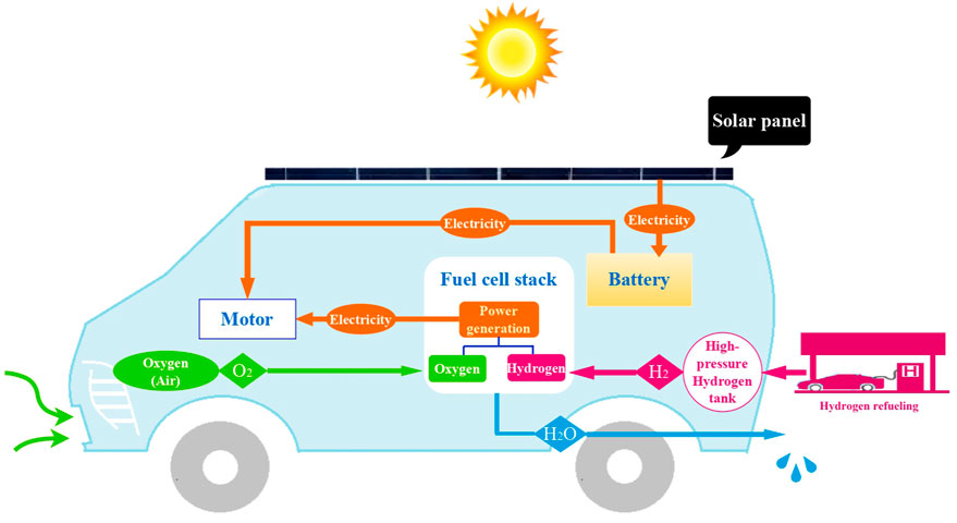
FIGURE 1. Energy flow diagram of hybrid source-fed EV.
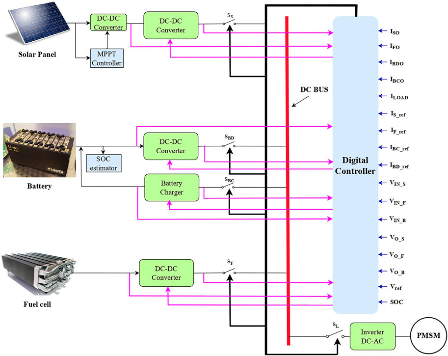
FIGURE 2. Hybrid power source-fed EV.
The mathematical modeling of the input sources is considered in Figure 3. The equations governing the equivalent circuit model of a solar cell are given in Eqs. (1)–(2).
where Isolar is the output current of the solar cell, which depends on the irradiance; IPHO is the light current, which depends on the irradiance; IDSH is the shunt-diode current; ISHU is the shunt resistor; ec is the electron charge; z is the diode ideal factor; k is the Boltzmann’s constant; Temp is the panel temperature; Vsolar is the output voltage of the solar cell, which depends on the atmospheric temperature; and Rseries and Rshunt are the series and shunt resistors, respectively.
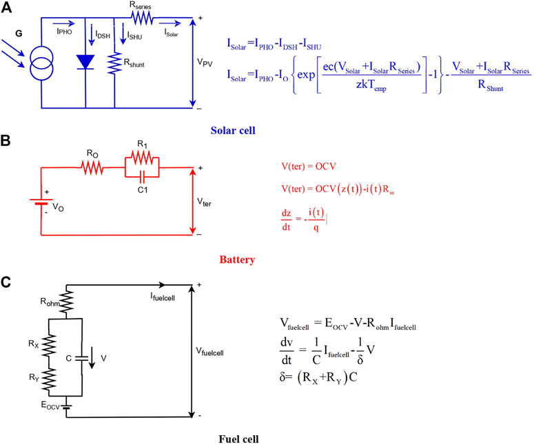
FIGURE 3. Equivalent circuit of input sources (A) solar cell, (B) battery, and (C) fuel cell in the proposed work.
The basic equivalent circuit of a battery model consists of series connection between a DC voltage source and an internal resistor that expresses the V(ter) and Rin. Internal resistance varies with electrolyte, SoC, and temperature. V(ter) is the terminal voltage, which can be measured in open circuit voltage, according to Eq. (3). Z(t) indicates the SoC, and q is the battery capacity as shown in Eqs (4) and (5).
Fuel cell model equations are shown in Eqs (6), (7), and (8), respectively.
where V is the voltage between the equivalent capacitor, Rohm is the ohmic resistor, δ is the fuel cell time constant, C is the equivalent capacitor, EOCV is the open circuit voltage, V fuelcell is the output voltage of fuel cell, and Ifuelcell is the output current of fuel cell.
2.1 Solar panel
A school van is considered as a reference for the proposed EV design, and the area expected to house the solar panel on the roof of the vehicle is well-suited. The size of the solar panel depends on the availability of roof space in the EV. The power rating of a single PV array is 555 W, and its dimensions are 7.5 by 3.8 feet. Hence, it is possible to place five solar panels on the roof, and they are connected in series. Significant problems in the solar PV system include low conversion efficiency and electrical energy that varies due to insolation changes (Rathod and Subramanian, 2022). Single solar panel ratings are Pmax = 555 W, Imp = 13.33 A, Vmp = 41.64 V, and Voc = 50.34 V (ENF, 2022). A PV-cell model has been developed in MATLAB/Simulink with varying irradiance and ambient temperature, and it has real-time solar irradiance data as input. Figure 4 depicts the different current, voltage, and power outputs of one solar panel, which exhibits 490 W at the maximum irradiance of 900 W/m2. The maximum amount of power extracted from the solar panel by means of a power electronic controller is referred to as MPPT. When output and input resistances are equal, MPPT is possible (Metwally Mahmoud, 2022). Hence, a solar panel’s resistance has to match the load resistance by using a suitable power conditioner circuit like a DC–DC converter. By adjusting the duty cycle, the DC–DC converter’s output voltage can be changed to maintain solar panel resistance according to changes in irradiance and temperature. By changing the duty ratio or duty cycle, the output voltage of the converter can be changed to keep the resistance of the solar panel constant as the amount of light and temperature changes.
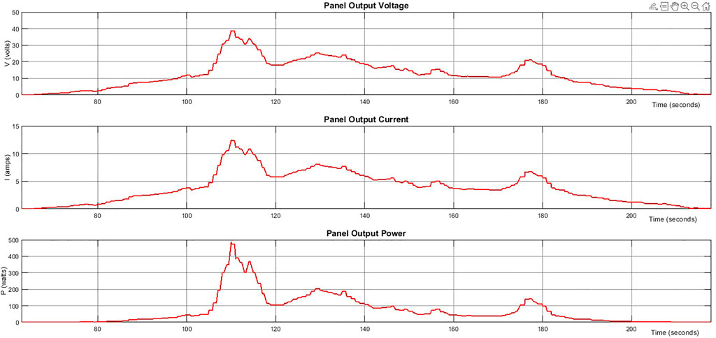
FIGURE 4. Solar panel output voltage, current, and power.
A solar PV array’s characteristics are unpredictable due to insolation and temperature changes. Hence, MPPT is needed for extracting maximum power and to overcome irradiance and temperature fluctuations. Of all the MPPT methodologies, incremental conductance (INC) is the most suitable, considering its high effectiveness, accuracy, ease of implementation, and speed of response (Loukriz et al., 2016). Traditional MPPTs with a fixed step size deliver less output power, and every step track needs a random change for different weather conditions, which is hard. The MPPT algorithm of the VSS–INC method is shown in Figure 5 and the corresponding equations are given in Eqs (9) and (10).
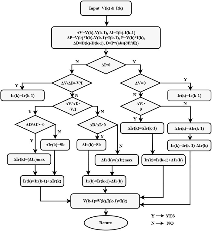
FIGURE 5. MPPT algorithm based on VSS–INC method.
From the aforementioned Eqs (9) and (10),
Here, the variable step is
The fixed value of the scaling factor does not fulfill the MPPT requirement due to sudden variations in the irradiance and temperature. So the optimal value for this scaling factor is fixed at 3. This VSS INR-based MPPT is switched by threshold function values (D), which gives the product of the solar panel’s exponential power output (Pe) and PV array’s absolute value of the derivative (dP/dI) in the following Eq. (13).
In Eq. (14), (dP/dI) represents the current versus the slope of the power.
The DC–DC converter is used to identify the MPP by varying the duty cycle of the solar array by continuously changing the operating current based on a variable step size. The controller regulates the DC–DC converter’s duty cycle according to the atmospheric conditions. The solar panel current set to operate at the reference current (Ir), so
At time k,
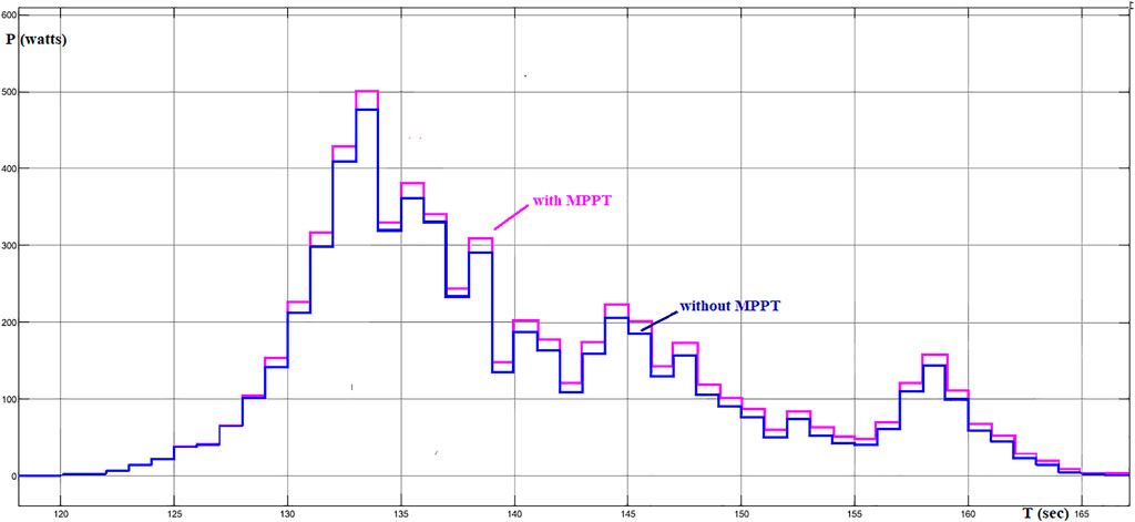
FIGURE 6. Simulated power output of solar panel (with and without MPPT).
2.2 Battery
A battery is one of the main energy storage elements that can charge and discharge electrical energy based on the application. Because of the numerous benefits, most EV companies prefer lithium-ion batteries over other types. Owing to their fundamentally safe chemistry and nearly 50% less weight than lead–acid batteries, lithium-ion batteries are ideal for EV adoption due to their long life, non-hazardous nature, and lack of maintenance. A battery is a better source than a fuel cell or solar panel because power management can be accomplished through energy charge and discharge whenever the system is more efficient. The range of an EV is determined by monitoring the battery’s level of charge, which gives reliability to drivers. The state of charge gives a control signal to charge the battery when it reaches 20%, and the battery receives a discharge command signal from the controller when the SoC attains 80% of the battery. Figure 7 shows the charging and discharging curve for the battery during one cycle.
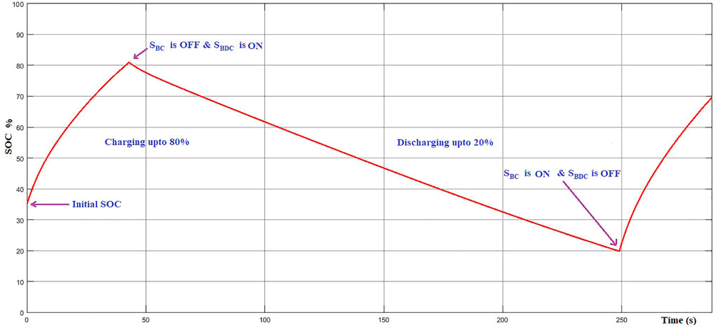
FIGURE 7. Charging and discharging based on SoC.
The battery has to provide the electrical energy to propel the EV, irrespective of other sources because it has major capabilities when solar and hydrogen fuels are not present. Solar panels charge the battery based on the amount of irradiance and temperature when an EV is parked in sunlight. When the SoC decreases by 20% while the EV runs, the fuel cell powers the vehicle and the solar panel begins to charge the battery (Venkatramanan and John, 2019). If there is an excessive load taken by passengers or an uphill driving motion of an EV, the battery needs to satisfy the load with the fuel cell, so power flow is shared by the battery and fuel cell depending upon their availability. Whenever the battery needs to be discharged, the boost converter is used, and if the battery wants to be charged, the buck converter is used. The lithium-ion battery is used, and its specifications are 22.4 kW h/400 Ah, 48 V (Mishra, 2022).
2.3 Fuel cell
The fuel cell is an emerging and promising power source that is available in many specifications and can fulfill the needs of power distribution to standalone systems, mobile power generation, acting as a power backup, and transportation such as an FC bus, FC train, and FCEV. The proposed work considered the proton-exchange membrane (PEM) fuel cell as one of the major sources in the hybrid power source due to its lightweight, compact design, fast start, flexibility in fuel input, and low cost compared to other types. The fuel cell ratings are as follows: nominal voltage is 350 V, nominal current is 250, and power is 30 kW. The fuel cell’s role in the proposed work is to serve as a backup power source for the battery because if solar and battery power are insufficient during short power demands, the fuel cell can deliver power to achieve the load’s power demand. When the battery gets discharged up to the SoC (20%) level and solar power is unavailable, the fuel cell, as in a FCEV, will act as the primary power source for the EV motor. Because of the high cost of hydrogen fuel, the controller prioritizes solar energy, followed by batteries, and finally, fuel cells.
3 Digital control strategy
The proposed work has a digital controller which is used to keep the DC bus’s voltage constant and power sharing controlled by adjusting the current from each source to the permanent magnet synchronous machine, depending on the input sources (Zandi et al., 2011).
3.1 Constant voltage at DC bus
Each and every source is connected in parallel with the DC common bus through a DC–DC converter, which provides the constant voltage in the DC bus. The DC–DC converter’s duty cycle must provide a constant output voltage regardless of input voltage or load variation. Solar panel, battery, and fuel cell deliver the voltage based on their input energy, and a digital controller feeds the proper duty cycle to their respective converters to keep the same or equal voltage in the DC bus and that voltage should be free from ripples (Mahmoud et al., 2022b). The digital controller generates and modifies the boost converter’s duty cycle in order to set 300 V as the reference voltage (9), and
Here,
where

FIGURE 8. Flow chart for digital control.
3.2 Power management
A digital controller is used to achieve power management in the EV system. The controller receives a few input signals, such as SoC, input and output voltages of all DC–DC converters, load current (
➢ The first priority of PMS is the solar panel because solar energy is free and abundantly available from nature.
➢ If load demand is increased further, the battery must discharge in the presence of the solar panel simultaneously to supply the required amount of power. When the solar panel generates excessive power, the battery can charge.
➢ If the load cannot be met by the aforementioned sources, fuel cells, along with solar panels and batteries, provide power.
The voltage at the DC bus is maintained at 300 V as the reference voltage (
where,
where
If the space between
If
When the load increases, the battery and solar panels together deliver power to the PMSM to satisfy the increment in load, and the controller is coded to discharge the battery when the SoC is more than 20%.
The duty ratio tuning of the battery’s boost converter, as in Eq. (27), occurs when the actual discharging current equals the reference discharging current
The tuning of F is automatic, as per Eq. (28).
When the load of PMSM is met by power from the solar panel, battery, and fuel cell,
4 Results and discussion
The duty cycle of all the DC–DC converters varies as per the availability of input sources, which is calculated and fed into the controller to maintain the voltage; the output of the digital controller sends a control signal as a pulse to the switches; and it can attach and/or detach the input sources as per the program fed into the controller. The real-time electric car, the BJEV EC180, has a 30-kW motor that is available on the market (Ding, 2020). As a result, the 30-kW machine is selected for this proposed work. A PMSM is connected to the DC bus using a three-phase inverter, which has 30 kW of power, 200–450 V, 3000–6000 rpm, and an efficiency of 95% (PMSM, 2022). Due to the vehicle’s uphill motion, passenger weight, and more luggage, the load of PMSM gets increased. The instantaneous change in load current always compares to the available source current and manages the power as per the present condition of the sources. In addition to PMS, the proposed controller performs MPPT operation to enhance power reliability and keeps the same voltage on the common DC bus. According to the load variation, all five switches, namely, the solar switch (SS), fuel cell switch (SF), battery discharge switch (SBDC), battery charge switch (SBC), and load switch (SL), gets the signal from the controller in the form of 0 and 1, where 0s stand for off and 1s stand for on the switches.
The switching pattern of all switches is described in Table 1, which has the 12 possible sequences of power management in the proposed work. For example, in case I, the EV is in the parked mode under the Sun, and useful solar power gets charged through the DC bus and buck converter. A FCEV operation in an EV is denoted by Case V, in which the battery is discharged and attains 20% SoC while solar energy is also unavailable, such as at night. In case VII, when the SF and SBC switches are in the “off” state, solar and battery power are combined to propel the EV. Case VIII is like a normal BEV; the battery is the only source to accelerate the EV, and the rest of the switches are in the off position. The combination of conventional BEV and FC operation indicates that case IX uses battery backup power and hydrogen energy. In case XI, all the sources are together to maintain the load demand of the EV, and case XII indicates an EV parked at night, where all the switches are in the off position. The controller delivers various pulses to connect or disconnect the sources with various possible combinations of power management techniques, as shown in Figure 9.

TABLE 1. Switching pattern.
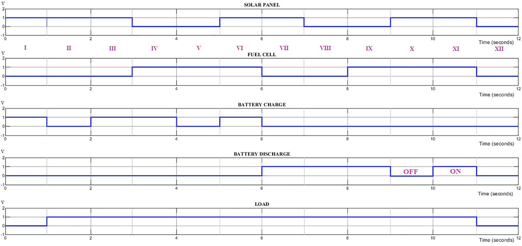
FIGURE 9. Control pulse generation with various possible combinations.
Figure 10 shows the power management of the controller when EV is running smoothly without any load variations and all the switches are in the on (one) position. To compensate for the 30 kW load power, the solar, battery, and fuel cell deliver power based on the power present in each. The main aim of this PMS is to capture and use more power from the solar source while giving the least importance to the fuel cell source because of the hydrogen cost. Figure 10 shows that in the time between 2 and 3 s to reach the PMSM’s load demand, the battery supplies 61.6%; the fuel cell, 30%; and the solar panel, 8.4%. Out of the total 30 kW of PMSM load, the battery provides 18.48 kW, the fuel cell provides 9 kW, and solar provides the remaining 2.52 kW. Compared to EVs available in the market, this output from the digital controller achieves nearly 40% less operation from the battery and improves the health of the battery. From 4 to 8 s, the vehicle is in parking mode when solar energy is present. Hence, the controller sends control signals to turn off (zero) all switches except the solar switch, and the battery gets charge from the solar panel, which is 2500 W. In this stage, solar irradiance determines the battery charge. If partial shading or low irradiance occurs, the amount of power generated by the solar panel is reduced accordingly, and the battery charging power also gets reduced. In comparison to conventional FCEVs, the proposed work reduces fuel cell power and minimizes hydrogen usage. At the same time, charging and discharging within the 20%–80% range improves the battery’s health. This digital controller reduces the transients whenever the switching operation occurs, and Figure 10 and Figure 11 indicate the controller has reached the quick steady state. The load changes while driving the EV are shown in Figure 11.
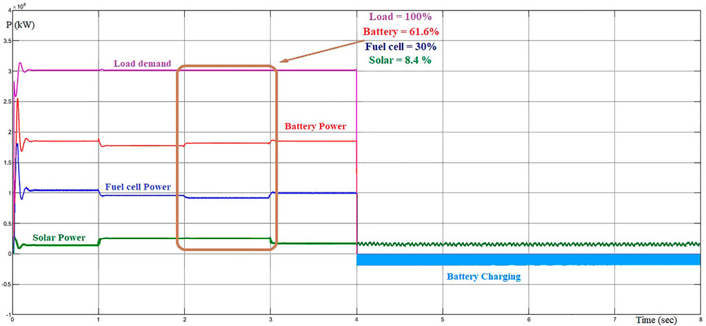
FIGURE 10. Power management of digital controller.
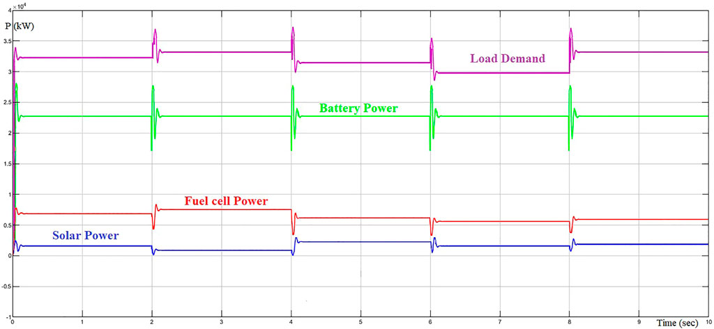
FIGURE 11. Power management based on varying load demand.
The EV is running with some load variations, where the battery delivers 2.26 kW of constant power and the remaining sources deliver the power with respect to availability. Figure 11 shows that any partial shade condition reduces solar panel generation by 2–4 s when it produces 1050 W, where fuel cell compensates for that power demand from solar power and battery delivers the same power. When compared to the existing system, the proposed digital controller-based PMS provides better response, higher accuracy, easy programming, and more reliability, as shown in Table 2.
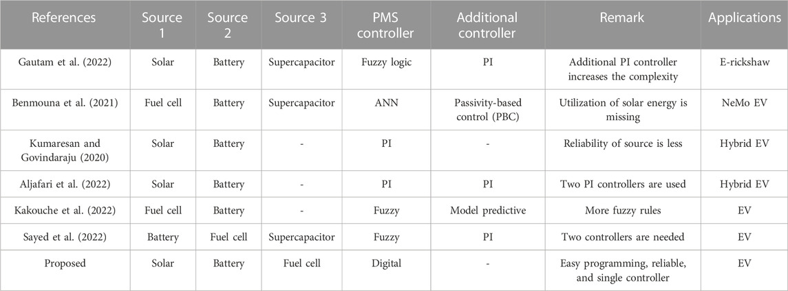
TABLE 2. Comparative analysis.
5 Hardware setup
The hardware prototype for the proposed digital controller has been developed and is shown in Figure 12. It has three boost converters and one buck converter, a DC bus, relay switches, a controller, a battery charger circuit, and a current sensor. Solar panel, fuel cell, and battery are connected to the boost converters to generate a higher voltage level (24 V) at the output side, where the controller maintains the DC bus voltage (24 V) based on the change in duty cycle from the boost converters. Series connections of diodes are used to avoid circulating current at transient times, and the parallel connection of capacitors has been used for ripple-free DC bus voltage. The current sensor (CCYHCS-ES5) is connected to monitor changes in the load and sources. A 250-W solar panel, with Voc = 37.25 V, Isc = 8.95 A, Imp = 8.35 A, and Vmp = 29.95 V (Sharma and Chauhan, 2022), and a 12-V lead-acid battery are used. The power management verification is shown in Figure 12, where an LCD display shows that the power management has been performed using a controller with respect to available sources. Four LCD displays are shown in Figure 12, in which the first display illustrates the load satisfied by solar, fuel cell, and battery power; the second display shows the battery and fuel cell combined for the power management operation; and the third display and fourth display explain the battery-fed PMS and fuel cell-fed PMS, respectively. Figure 13 depicts the duty cycle of the boost converter in the solar panel, fuel cell, and battery to maintain a constant DC bus voltage. Figure 14 illustrates the output voltage (13.15 V) of the battery charger to charge a 12-V battery.
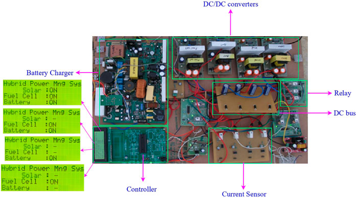
FIGURE 12. Hardware structure of proposed controller.
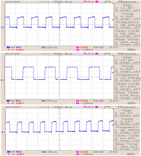
FIGURE 13. Duty cycle of boost converters fed with solar, fuel cell, and battery.
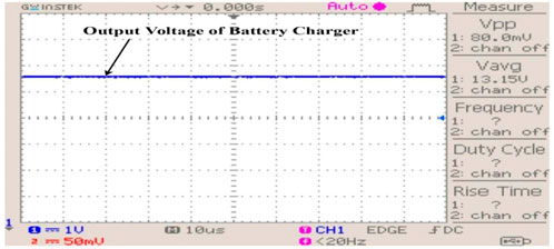
FIGURE 14. Output voltage of battery charger.
6 Conclusion
The proposed digital controller-based PMS is commendable in that it shares power from different input sources in various combinations in order to meet the power demand of PMSM, and this is proven using the results of the controller’s output. The novel digital controller achieves 40% power burden (12 kW) in the battery that enhances the life of the battery compared to existing EVs. The role of the digital controller in the proposed work is to maintain the flow of power among the sources and load in order to meet load variation. The advantages of this method include simple implementation and reduced complexity. This controller is applicable to all types of motors used in EVs and any microgrid architecture. The future scope of this work is extended to include a novel DC–DC converter topology with PMS, and the power quality issues can also be considered.
Data availability statement
The original contributions presented in the study are included in the article/Supplementary Material; further inquiries can be directed to the corresponding author.
Author contributions
GM—design, simulation, and experimental development. RS—supervision and paper drafting.
Conflict of interest
The authors declare that the research was conducted in the absence of any commercial or financial relationships that could be construed as a potential conflict of interest.
Publisher’s note
All claims expressed in this article are solely those of the authors and do not necessarily represent those of their affiliated organizations, or those of the publisher, the editors, and the reviewers. Any product that may be evaluated in this article, or claim that may be made by its manufacturer, is not guaranteed or endorsed by the publisher.
References
Aljafari, B., Devarajan, G., Arumugam, S., and Vairavasundaram, I. (2022). Design and implementation of hybrid PV/Battery-Based improved single-ended primary-inductor converter-fed hybrid electric vehicle. Int. Trans. Electr. Energy Syst. 2022, 1–11. doi:10.1155/2022/2934167
Barelli, L., Bidini, G., Ciupăgeanu, D. A., Pianese, C., Polverino, P., and Sorrentino, M. (2020). Stochastic power management approach for a hybrid solid oxide fuel cell/battery auxiliary power unit for heavy duty vehicle applications. Energy Convers. Manag. 221, 113197. doi:10.1016/j.enconman.2020.113197
Benhammou, A., Tedjini, H., Guettaf, Y., Soumeur, M. A., Hartani, M. A., Hafsi, O., et al. (2021). Exploitation of vehicle’s kinetic energy in power management of tow -wheel drive electric vehicles based on ANFIS DTC-SVM comparative study. Int. J. Hydrogen Energy 46, 27758–27769. doi:10.1016/j.ijhydene.2021.06.023
Benmouna, A., Becherif, M., Boulon, L., Dépature, C., and Ramadan, H. S. (2021). Efficient experimental energy management operating for FC/battery/SC vehicles via hybrid artificial neural networks-passivity based control. Renew. Energy 178, 1291–1302. doi:10.1016/j.renene.2021.06.038
Ding, N. (2020). Energy management system design for plug-in hybrid electric vehicle based on the battery management system applications ning ding. New Zealand: Auckland University of Technology.
ENF (2022). ENF ltd. Available at: https://www.enfsolar.com/pv/panel-datasheet/crystalline/51862 (Accessed on October 1, 2022).
Fu, Z., Wang, H., Tao, F., Ji, B., Dong, Y., and Song, S. (2022). Energy management strategy for fuel cell/battery/ultracapacitor hybrid electric vehicles using deep reinforcement learning with action trimming. IEEE Trans. Veh. Technol. 71, 7171–7185. doi:10.1109/TVT.2022.3168870
Gautam, A. K., Tariq, M., Pandey, J. P., and Verma, K. S. (2022). Optimal power management strategy by using fuzzy logic controller for BLDC motor-driven E-rickshaw. J. Intell. Fuzzy Syst. 42, 1089–1098. doi:10.3233/JIFS-189774
Gharibeh, H. F., Yazdankhah, A. S., Azizian, M. R., and Farrokhifar, M. (2021). Online energy management strategy for fuel cell hybrid electric vehicles with installed PV on roof. IEEE Trans. Ind. Appl. 57, 2859–2869. doi:10.1109/tia.2021.3061323
Kakouche, K., Rekioua, T., Mezani, S., Oubelaid, A., Rekioua, D., Blazek, V., et al. (2022). Model predictive direct torque control and fuzzy logic energy management for multi power source electric vehicles. Sensors 22, 5669. doi:10.3390/s22155669
Katnapally, A., Manthati, U. B., Chirayarukil Raveendran, A., and Punna, S. (2021). A predictive power management scheme for hybrid energy storage system in electric vehicle. Int. J. Circuit Theory Appl. 49, 3864–3878. doi:10.1002/cta.3119
Kumaresan, J., and Govindaraju, C. (2020). Development of a power management algorithm for PV/battery powered plug-in dual drive hybrid electric vehicle (DDHEV). Electr. Power Components Syst. 48, 70–85. doi:10.1080/15325008.2020.1736212
Lee, H., and Cha, S. W. (2021). Energy management strategy of fuel cell electric vehicles using model-based reinforcement learning with data-driven model update. IEEE Access 9, 59244–59254. doi:10.1109/ACCESS.2021.3072903
Loukriz, A., Haddadi, M., and Messalti, S. (2016). Simulation and experimental design of a new advanced variable step size incremental conductance MPPT algorithm for PV systems. ISA Trans. 62, 30–38. doi:10.1016/j.isatra.2015.08.006
Mahmoud, M. M., Aly, M. M., and Abdel-Rahim, A.-M. M. (2020). Enhancing the dynamic performance of a wind-driven PMSG implementing different optimization techniques. SN Appl. Sci. 2, 684. doi:10.1007/s42452-020-2439-3
Mahmoud, M. M., Atia, B. S., Abdelaziz, A. Y., and Aldin, N. A. N. (2022). Dynamic performance assessment of PMSG and DFIG-based WECS with the support of manta ray foraging optimizer considering MPPT, pitch control, and FRT capability issues. Processes 10, 2723. doi:10.3390/pr10122723
Mahmoud, M. M., Esmail, Y. M., Atia, B. S., Kamel, O. M., AboRas, K. M., Bajaj, M., et al. (2022). Voltage quality enhancement of low-voltage Smart distribution system using robust and optimized DVR controllers: Application of the harris hawks algorithm. Int. Trans. Electr. Energy Syst. 2022, 1–18. doi:10.1155/2022/4242996
Metwally Mahmoud, M. (2022). Improved current control loops in wind side converter with the support of wild horse optimizer for enhancing the dynamic performance of PMSG-based wind generation system. Int. J. Model. Simul. 10, 1–15. doi:10.1080/02286203.2022.2139128
Mishra, S. (2022). Lithium battery India 3.5kWh to 55kWh and more. Available at: https://vmechatronics.com/lithium-ion-battery-lirackeco.php (Accessed on October 24, 2022).
Mounica, V., and Obulesu, Y. P. (2022). Hybrid power management strategy with fuel cell, battery, and supercapacitor for fuel economy in hybrid electric vehicle application. Energies 15, 4185. doi:10.3390/en15124185
Oubelaid, A., Albalawi, F., Rekioua, T., Ghoneim, S. S. M., Taib, N., and Abdelwahab, S. A. M. (2022). Intelligent torque allocation based coordinated switching strategy for comfort enhancement of hybrid electric vehicles. IEEE Access 10, 58097–58115. doi:10.1109/ACCESS.2022.3178956
Oubelaid, A., Alharbi, H., Humayd, A. S., Taib, N., Rekioua, T., and Ghoneim, S. S. M. (2022). Fuzzy-energy-management-based intelligent direct torque control for a battery—supercapacitor electric vehicle. Sustainability 14, 8407. doi:10.3390/su14148407
Oubelaid, A., Taib, N., Nikolovski, S., Alharbi, T. E. A., Rekioua, T., Flah, A., et al. (2022). Intelligent speed control and performance investigation of a vector controlled electric vehicle considering driving cycles. Electronics 11, 1925. doi:10.3390/electronics11131925
Oubelaid, A., Taib, N., Rekioua, T., Bajaj, M., Blazek, V., Prokop, L., et al. (2022). Multi source electric vehicles: Smooth transition algorithm for transient ripple minimization. Sensors 22, 6772. doi:10.3390/s22186772
Oubelaid, A., Taib, N., Rekioua, T., Bajaj, M., Yadav, A., Shouran, M., et al. (2022). Secure power management strategy for direct torque controlled fuel cell/supercapacitor electric vehicles. Front. Energy Res. 10, 1–17. doi:10.3389/fenrg.2022.971357
PMSM (2022). 30kw pmsm synchronous motor with controller for electric vehicle - buy 30kw motor for Ev,30kw motor for electric Vehicle,30kw pmsm synchronous motor product. Available at: https://www.alibaba.com/product-detail/30kw-Pmsm-Motor-30KW-PMSM-Synchronous_62596399715.html?spm=a2700.7724857.0.0.48373a0bpjk9rn&s=p (Accessed on July 7, 2022).
Rahulkumar, J., Narayanamoorthi, R., Vishnuram, P., Bajaj, M., Blazek, V., Prokop, L., et al. (2023). An empirical survey on wireless inductive power pad and resonant magnetic field coupling for in-motion EV charging system. IEEE Access 11, 4660–4693. doi:10.1109/ACCESS.2022.3232852
Rathod, A. A., and Subramanian, B. (2022). Scrutiny of hybrid renewable energy systems for control, power management, optimization and sizing: Challenges and future possibilities. Sustainability 14, 16814. doi:10.3390/su142416814
Saravanakumar, T., and Saravana kumar, R. (2022). Design, validation, and economic behavior of a three-phase interleaved step-up DC–DC converter for electric vehicle application. Front. Energy Res. 10, 1–17. doi:10.3389/fenrg.2022.813081
Saravanakumar, T., and Saravana kumar, R. (2023). Fuzzy based interleaved step-up converter for electric vehicle. Intell. Autom. Soft Comput. 35, 1103–1118. doi:10.32604/iasc.2023.025511
Sayed, K., Abdel-Khalek, S., Zakaly, H. M. H., and Aref, M. (2022). Energy management and control in multiple storage energy units (Battery–Supercapacitor) of fuel cell electric vehicles. Mater. (Basel) 15, 8932. doi:10.3390/ma15248932
Shanmugam, Y., Narayanamoorthi, R., Vishnuram, P., Bajaj, M., AboRas, K. M., Thakur, P., et al. (2022). A systematic review of dynamic wireless charging system for electric transportation. IEEE Access 10, 133617–133642. doi:10.1109/ACCESS.2022.3227217
Sharma, A., and Chauhan, B. (2022). 250 watt solar panel -- best price for 250w solar panel. Available at: https://kenbrooksolar.com/solar-panel/250-watt-solar-panel (Accessed on November 7, 2022).
Sharma, P., and Chinnappa Naidu, R. (2023). Optimization techniques for grid-connected PV with retired EV batteries in centralized charging station with challenges and future possibilities: A review. Ain Shams Eng. J. 14, 101985. doi:10.1016/j.asej.2022.101985
Soumeur, M. A., Gasbaoui, B., Abdelkhalek, O., Ghouili, J., Toumi, T., and Chakar, A. (2020). Comparative study of energy management strategies for hybrid proton exchange membrane fuel cell four wheel drive electric vehicle. J. Power Sources 462, 228167. doi:10.1016/j.jpowsour.2020.228167
Traube, J., Lu, F., Maksimovic, D., Mossoba, J., Kromer, M., Faill, P., et al. (2013). Mitigation of solar irradiance intermittency in photovoltaic power systems with integrated electric-vehicle charging functionality. IEEE Trans. Power Electron. 28, 3058–3067. doi:10.1109/TPEL.2012.2217354
Veerendra, A. S., Mohamed, M. R., Leung, P. K., and Shah, A. A. (2021). Hybrid power management for fuel cell/supercapacitor series hybrid electric vehicle. Int. J. Green Energy 18 (2), 128–143. doi:10.1080/15435075.2020.1831511
Venkatesan, M., Rajamanickam, N., Vishnuram, P., Bajaj, M., Blazek, V., Prokop, L., et al. (2022). A review of compensation topologies and control techniques of bidirectional wireless power transfer systems for electric vehicle applications. Energies 15, 7816. doi:10.3390/en15207816
Venkatramanan, D., and John, V. (2019). Dynamic modeling and analysis of buck converter based solar PV charge controller for improved MPPT performance. IEEE Trans. Ind. Appl. 55, 6234–6246. doi:10.1109/TIA.2019.2937856
Yuvaraj, S., Narayanamoorthi, R., Jagabar Sathik, M. A., and Almakhles, D. (2022). A comprehensive review of the on-road wireless charging system for E-mobility applications. Front. Energy Res. 10, 1–23. doi:10.3389/fenrg.2022.926270
Keywords: battery, DC–DC converter, digital controller, fuel cell, MPPT, electric vehicle
Citation: Mathesh G and Saravanakumar R (2023) A novel digital control scheme for power management in a hybrid energy-source environment pertaining to electric vehicle applications. Front. Energy Res. 11:1130401. doi: 10.3389/fenrg.2023.1130401
Received: 23 December 2022; Accepted: 06 February 2023;
Published: 24 February 2023.
Edited by:
Mohit Bajaj, Graphic Era University, IndiaReviewed by:
Adel Oubelaid, Université de Bejaia, AlgeriaPradeep Vishnuram, SRM Institute of Science and Technology, India
Copyright © 2023 Mathesh and Saravanakumar. This is an open-access article distributed under the terms of the Creative Commons Attribution License (CC BY). The use, distribution or reproduction in other forums is permitted, provided the original author(s) and the copyright owner(s) are credited and that the original publication in this journal is cited, in accordance with accepted academic practice. No use, distribution or reproduction is permitted which does not comply with these terms.
*Correspondence: R. Saravanakumar, cnNhcmF2YW5ha3VtYXJAdml0LmFjLmlu