 Sainan Xue
 Xin Zhang1
 Hu Ma
Hu Ma- 1School of Mechanical Engineering, Nanjing University of Science and Technology, Nanjing, China
- 2Xi’an Changfeng Research Institute of Mechanism and Electricity, Xi’an, China
- 3Troops with No. 93147, Chengdu, China
A direct connection test of a rotating detonation engine was conducted. The outer and inner diameters of the annular combustors were 206 and 166 mm, respectively. High enthalpy air was used as an oxidizer, and a mixture of hydrogen, carbon monoxide, and methane was used as fuel with a volume fraction of 5/4/1. The mixture was injected through small holes, and air was injected through annular slots. The effects of combustor length, width of annular slots, and the equivalent ratio on formation, development, propagation, and flameout of rotating detonation waves were analyzed, and several modes of rotating detonation were observed. It was found that when the width of the air annular slot was within the range of 3–5 mm, the pressure of the detonation wave was augmented with an increased slot width. As width increased, detonation waves became unstable. In study test conditions, an annular slot width of 6 mm was the critical condition for the formation of stable detonation. When the slot width was 4 mm and combustor length 160 mm, the phenomena of the conversion between single and double waves, double-wave collision, and conversion of the propagation direction occurred at different equivalent ratios. When the equivalent ratio was 1.2/1 and the slot width was within the range of 3–6 mm, the slot width was inversely related to the detonation wave velocity. When the slot width was 4 mm and the equivalent ratio was 1.0/1–1.2/1, the slot width was positively correlated with the detonation wave velocity. When the combustor length was shortened to 80 mm, the propagation mode of the detonation wave was changed to a single wave first and then to a double wave in the same direction, and the velocity reduced from 1130.69 to 1024.16 m/s. The injector used in the test inhibited the propagation of back pressure from the combustor.
1 Introduction
Rotating detonation engines (RDEs) can operate in a wide range of incoming velocities, which is considered by many researchers as the future power device. Compared with the traditional combustor, the rotating detonation combustor (RDC) has a simple and compact structure. Moreover, its high thermal efficiency can significantly improve the power performance and reduce fuel consumption, in line with the development concept of environmental protection.
At present, research on propellant types of RDE is very extensive, including hydrogen, methane, ethylene, and other gaseous fuels (Zhou et al., 2017; Tobias et al., 2019; Liu et al., 2020). In practical applications, the comprehensive advantage of liquid fuel is higher than that of gaseous fuel, and the study of kerosene and air as reactants has become conventional. WANG et al. (2017) studied the working modes of kerosene two-phase combustors with different equivalent ratios and found that the velocity of the detonation wave can reach 2,440 m/s in oxygen-rich conditions, with the velocity proportional to the oxidizer oxygen content. WANG et al. (2021a) researched the propagation characteristics of kerosene-air rotating detonation waves under different combustor structures and found that the increasing combustor width within a certain range is conducive to the propagation stability of the detonation wave. Li et al. (Bao-xing et al., 2021) found that the reducing combustor width leads to decreases in thrust stability. Wang et al. (2020) chose pyrolytic gases of kerosene as fuel and conducted experiments in oxygen-rich air to study the influence of the equivalent ratio and nozzle configuration changes on detonation combustion. The convergence nozzle helps in increasing the propagation velocity of the detonation wave. Hu et al. (Hong-bo et al., 2020) conducted experiments with gaseous kerosene and concluded that there is an optimal influence of oxygen concentration and airflow on wave velocity when oxygen is depleted.
The structure of RDC mainly revolves around annular, disk-shaped, and hollow structures. Although research on disk-shaped combustors began in the 1960s (Voitsekhovskii et al., 1969), there have been few related studies due to the complex shockwave system (Xia et al., 2022). The hollow combustor with a relatively simple structure has also been rarely studied (Meng et al., 2022; Xue et al., 2022). However, annular combustors have been a mainstream research object in RDEs, and relevant studies are extensive (Zhou et al., 2018; Kawasaki et al., 2019; Dunn et al., 2020). Zhang et al. (2022) designed a hydrogen-rich fuel combustion chamber and studied the propagation characteristics of rotating detonation waves under different equivalent ratios. When the equivalent ratio decreases in a test, the propagation mode of the detonation wave changes, which is successively a single-wave mode, single-double-wave alternating mode, and complex double-wave mode. Feng et al. (2022) made a numerical analysis of the flow field of kerosene-air annular combustors and concluded that when the total temperature of incoming air was high, the detonation wave height decreases with an increased equivalent ratio. Ge et al. (Gao-yang et al., 2022) mixed the air slot with the gasoline nozzle in a 90° collision injection, using the pre-detonator to ignite, and verified the feasibility of gasoline-air rotating detonation combustion in the annular combustor under the condition of an air inlet with a high total temperature. The short- and long-time tests under the condition of a high total temperature inlet have been successfully achieved, and the measured detonation frequency reached 1907.5 Hz. Yuan et al. (2021) observed the flow field with the shadow method, classified the structure of the detonation wave according to the change of the Mach stem, and analyzed the mechanism of different propagation modes.
In recent years, more and more studies have been carried out on combined engines with different intake modes for rotating detonation combustors instead of traditional combustors (Wang et al., 2021b). To overcome the “thrust trap,” it is very important to explore the combination of ram intake and continuous rotating detonation combustors. Zheng et al. (2022) completed the test of a rotating detonation ramjet combustor using hydrogen fuel under the condition of Mach number 3.1 and found that the equivalent ratio is a factor affecting the propagation frequency and stability of detonation waves. Wang et al. (2022) used ethylene and kerosene fuels to sustain rotating detonation wave propagation at normal temperature under an incoming flow Mach number of 5 and propagation frequency of the detonation wave at 6,420 Hz, with the flow field in the isolator affected by the back pressure from the RDC.
To improve the performance of the rotating detonation engine, this study adopted air and gas mixtures with the same main composition as kerosene as the reactants. The isolator, injector, and annular combustor were designed, and an experimental study was performed under the condition of high enthalpy airflow. Based on analytical measurement results from sensors arranged in the isolator and combustor, the influence of the air slot width, equivalent ratio, and combustor length on the rotating detonation engine was compared.
2 Experimental system and methodology
2.1 Experiment system
This test is a direct connection test, which mainly studies the rotating detonation combustion based on a mixed fuel (H2/CO/CH4 at 5/4/1, v/v) under high enthalpy airflow. The test system is composed of seven parts, namely, a compressed air supply system, air heating system, fuel supply system, ignition system, RDE, control, and test system. The connections between the various parts of the system are shown in Figure 1A.
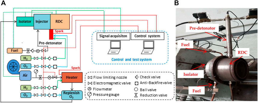
FIGURE 1. Diagram of the experiment system. (A) Schematic representation of the experiment system. (B) Photograph of the RDC test system.
The air, stored in the large-capacity high-pressure gas cylinder, flowed through the gas filter, pressure-reducing valve, vortex flowmeter, and electromagnetic valve through the compressor and finally into the heater. The rate of airflow could be adjusted between 0.2 and 2.0 kg/s, and the mass flow of air was selected at 580 g/s. The heating system adjusted the temperature rise by controlling the hydrogen supply so that the incoming total temperature promptly reached a range from 500 to 1000 K. The oxygen supplement device was used to ensure the constant content of each component in hot air.
In testing, a spark plug with an ignition energy of 50 mJ was used as the ignition source to release the flame and ignite the pre-detonator, which was full of hydrogen and oxygen (H2 and O2, respectively).
The testing engine consisted of an isolator, injector, and RDC (Figure 1B). Pinholes were drilled on the outer wall of the isolator and combustor to monitor signals at high frequency and steady pressure.
The control system realized the operation and shutdown of the RDC through the on-off behavior of the fuel and oxidizer solenoid valves and timing of spark plug ignition. The National Instruments high-frequency data acquisition system had a single channel sampling frequency of 2 M/s and a 16-bit analog-to-digital converter, which synchronously measured multichannel pressure signals.
2.2 Experimental methodology
To be reused in future tests, the RDE was designed in a modular manner. The isolator, injector, and walls of the combustor were all adapted as detachable parts. In the engine, there was a circle-to-ring isolator, a slot-adjustable injector, and an annular combustor. The axial length of the isolator was 200 mm, and the diameter was 118 mm. The length of the injector was 90 mm, and 90 injection holes were distributed in the circumference. The combustor’s outer diameter was 206 mm, inner diameter was 166 mm, and length was from 80 to 160 mm. The total length of the RDE was not more than 450 mm. High enthalpy airflow entered the isolator from the entrance (Figure 2, green dotted line), moved along the flow direction (blue arrow), and mixed and reacted with the injected fuel mixture gas. The combustion reaction products and unreacted gaseous mixture were finally discharged from the outlet (red dotted line).
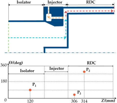
FIGURE 2. Locations of the sensors.
The pressures of the fuel plenum, air plenum, isolator, and RDC were measured by sensors, with the corresponding pressure signals denoted as Pfuel, Pair, Pi, and Pc. Piezoelectric high-frequency pressure sensors were used in the isolator and combustor to measure high-frequency dynamic pressure signals and were installed in the flush mode. The sensor P1 installed in the isolator was located 120 mm away from the isolator entrance and used to analyze the impact of detonation waves on the flow field in the upstream isolator. Sensors P2 and P3, installed in the combustor, were, respectively, arranged at axial distances of 314 and 306 mm with a circumferential interval of 90°, which monitored the direction of propagation of the rotating detonation wave.
A six-channel timing control module was used to control the test process; the timing sequence of the control scheme is shown in Figure 3. First, the sensor was triggered to start the data acquisition system recording pressure changes in the engine. Then, after connecting the cold air main line, H2 and O2 were quickly fed into the heater and ignited. After the heater had operated for 0.5 s, the mixture fuel was ejected through holes in a uniform array, mixed with high enthalpy air to form a fresh reaction mixture, and filled into the combustor. When the pre-detonator was filled with H2 and O2, the supplies of H2 and O2 were shut off and the spark plug was used to ignite the detonation, forming a high-temperature and high-pressure jet into the RDC. After the mixture was ignited, the rotating detonation wave was established. Finally, the supply of fuel, hot air, and cold air was turned off in order.
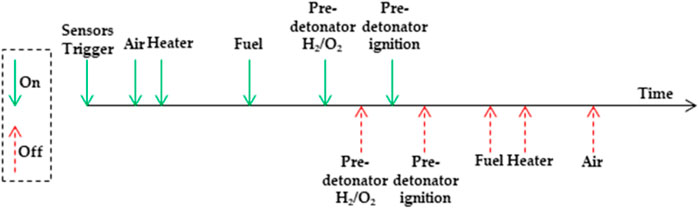
FIGURE 3. Time sequence of the experimental test.
3 Results and discussion
3.1 Operation process analysis
As heated air flowed into the combustor, the total temperature was 600 K, the mass flow rate 580 g/s, the width of the annular slot 4 mm, and the mass flow rate of fuel mixture 106 g/s. When the equivalent ratio was 1.2/1, pressure signals in the engine were collected. Due to the temperature drift phenomenon of the high-frequency pressure sensor in the high-temperature combustion environment, the original signal was filtered and a filtered pressure change curve with time during the operation was obtained (Figure 4).
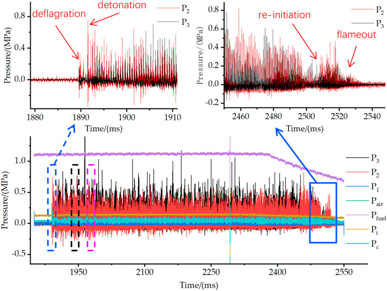
FIGURE 4. Results of operating at ER = 1.2 and lw = 4 mm.
The rotating detonation wave was successfully initiated and self-sustained from time t = 1891.4–2,382.2 ms. After the fuel supply was shut off, the rotating detonation wave still maintained a stable propagation. When the mixture pressure unceasingly dropped, the mixing efficiency with air changed. Thus, the decoupling process was re-initiated near t = 2,499.7 ms. As the mixture pressure continued to decline, the detonation wave was decoupled and disappeared, and the engine finally shut off. The combustor pressure Pc rapidly rose at the initial stage of detonation wave formation and then quickly stabilized. After secondary decoupling of the detonation wave, the combustor pressure gradually descended to the initial state. Pressure curves of the air plenum and isolator both fluctuated around 0.13 MPa and almost coincided. The fuel plenum pressure was stable at 1.14 MPa, much higher than the pressure of the isolator, which ensured mixed gas injection.
To analyze the initiation process of the rotating detonation wave in detail, the curves of the measurement signals in the combustor were amplified over the time axis range of 1880–1910 ms. The first pressure peak on the P3 curve in the figure occurred at t = 1889.6 ms. After 0.2 ms, the P2 sensor captured the first pressure peak, after which the pressure briefly attenuated, which could be caused by the ignition of the pre-detonator. The deflagration-to-detonation process (DDT) occurred before the detonation was fully established at t = 1891.4 ms. The operating mode of the combustor changed quickly from rapid deflagration at the initial ignition to the single wave mode. The pressure curves from 1938 to 1942 ms in the black dotted box were partially enlarged. The rotating detonation wave experienced five complete cycles during the period (Figure 5A). In a single cycle, the pressure peak of P3 was always measured before that of P2. The time difference was recorded as δt = 1939.0–1938.9 = 0.1 ms. The single period was 0.5 ms, and the detonation wave velocity was ∼1161 m/s.
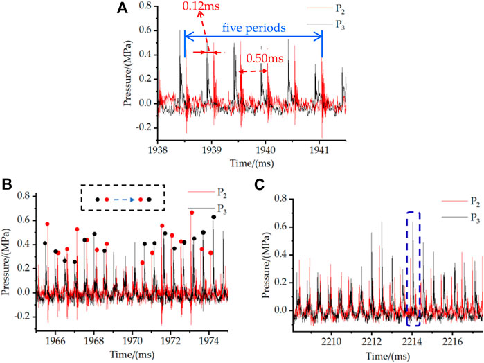
FIGURE 5. Different modes of the propagation: (A) Propagation of the single wave. (B) Reversion of waves. (C) Collision of double waves.
From the time of 1965 ms, the detonation wave completed the process of diversion within 10 ms (Figure 5B, purple-dotted box). The peak of P3 appeared in front of the peak of the P2 curve, and the time difference was 0.13 ms. Near t = 1968 ms, the pressure curve began to arise double at the peak, and near t = 1970 ms, the P2 curve showed a saddle shape. At P3, a new shockwave was formed, and its propagation direction changed under the effect of the collision of the two waves. After t = 1971.5 ms, the order of the peaks exchanged, and the time difference remained. This indicated that the propagation velocity of the detonation wave was almost unaffected by the change in direction.
It was found from measurement results that the direction of the detonation wave had changed many times, and a single–double wave conversion and double-wave collision appeared in each transition process. A two-wave collision occurred near the position of the P3 sensor, which made the weaker wave for the two waves decouple and disappear (Figure 5C). The energy of the weaker wave was absorbed by the remaining shockwaves to form a rotating detonation wave with stronger energy. The maximum pressure was approximately the sum of the collision wave peaks, reaching 0.64 MPa.
When the fuel supply was shut off, the pressure in the fuel plenum gradually dropped. The sensor detected that the detonation wave did not immediately extinguish, but the peak pressure tended to attenuate. When the injection pressure was reduced, the fuel penetration depth declined, resulting in a lower mixing efficiency and a slower detonation velocity. In this manner, the filling time of the reactants was prolonged, such that the filling height of the fresh reactants increased and the mixing time extended. When the height reached a certain value, a new detonation wave was triggered under the condition of an appropriate equivalent ratio, which might have been the cause of re-initiation (Figure 4).
The pressure plot showed the signal measured by sensor P1 in the isolator, which was based on 0 MPa and oscillated up and down, not exceeding 0.05 MPa (Figure 6). This indicated that the sensors did not capture the signal of the forward shockwave generated by the detonation wave in the combustor. The circle-to-ring intake structure adopted in the test played a certain role in inhibiting back pressure in the RDC.
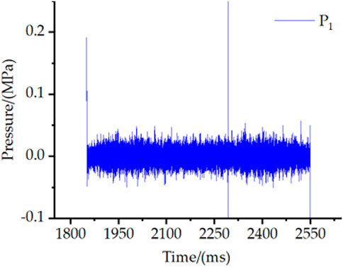
FIGURE 6. High-frequency signal in the isolator.
3.2 Influence of the width of the air inlet
Based on the test conditions in Section 3.1, the injector was replaced for testing. The widths of the air annular slots were 3, 4, 5, or 6 mm. The characteristic parameters obtained under the four conditions are shown in Table 1.
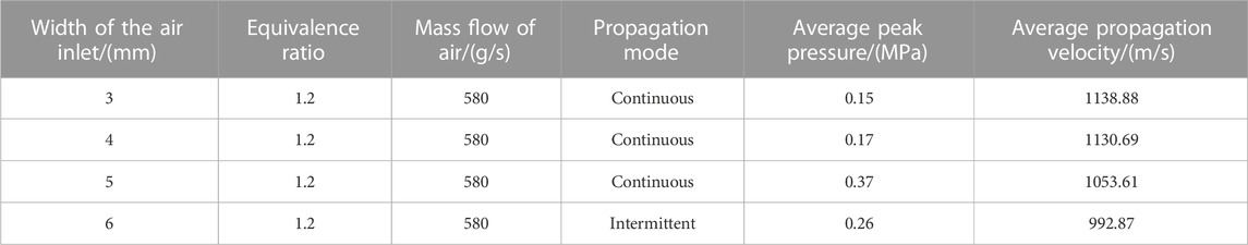
TABLE 1. Experimental parameters with different widths of the air inlet.
When the air inlet width was 3 mm, the curve of the pressure in the combustion chamber with time showed that at t = 2,585.9 ms, the sensor captured the peak pressure of the detonation wave for the first time, with a value of 0.37 MPa (Figure 7A). After the gas supply was turned off, the peak pressure decayed gradually until decoupling, which was different from the data with 4 mm width.
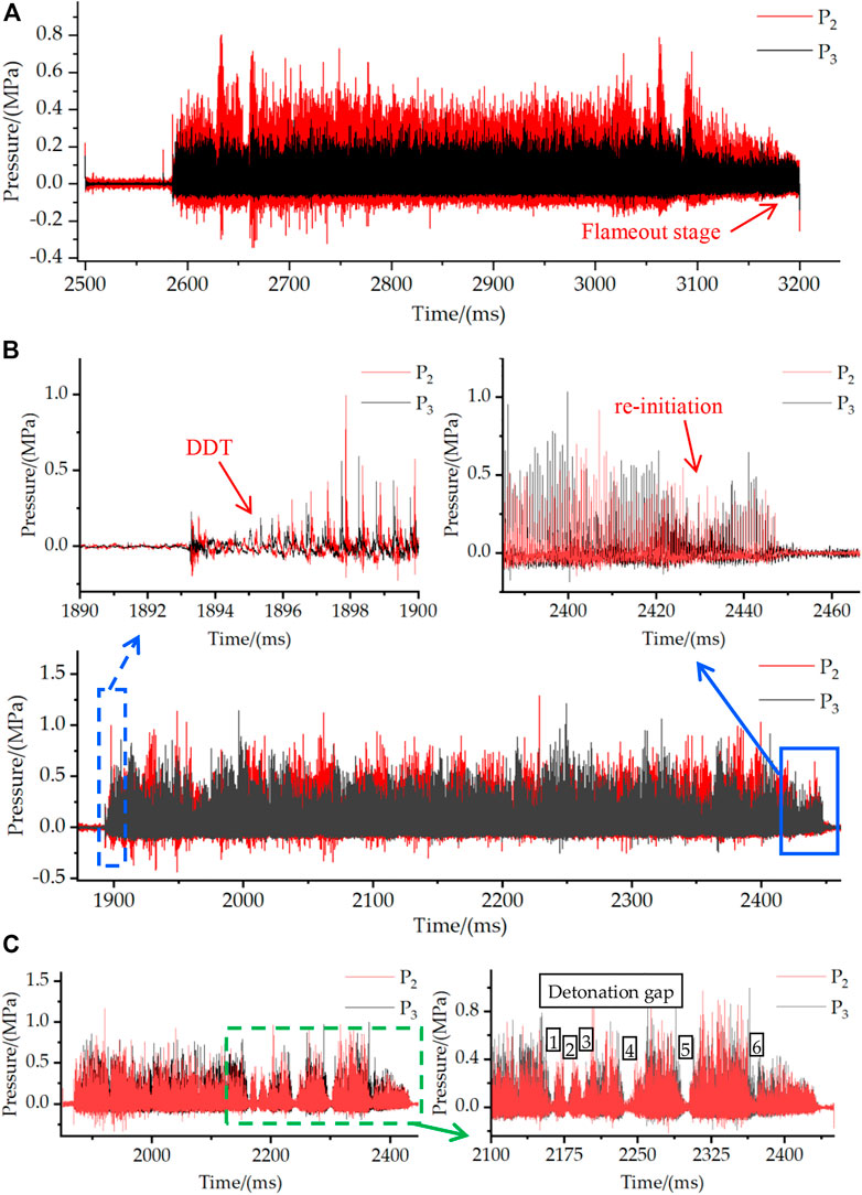
FIGURE 7. Results of operating at different widths of the air annular slot: (A) ER = 1.2 and lw = 3 mm; (B) ER = 1.2 and lw = 5 mm; (C) ER = 1.2 and lw = 6 mm.
When the slot width was 5 mm, the variation trend of the filter curve was similar to the test data in Section 3.1. The DDT process was experienced in ignition (Figure 7B, blue-dashed box, flameout stage partially enlarged in the solid-line box). The phenomenon of re-initiation was observed again, with the average peak pressure increased to 0.37 MPa.
At 6 mm slot width, there were several interruptions in the engine (Figure 7C, black boxes). The combustor pressure dropped sharply several times, leading to repeated processes of decoupling, flameout, and re-initiation. The main reason for intermittent detonation was that the energy of the detonation wave was low. The mass flow rate of the mixed gas remained unchanged, and the width of the air gap increased, such that the filling speed of reactants decreased. As a result, the fuel mixing efficiency was reduced, and the energy released by chemical reactions was reduced.
From 2,700 ms, pressure signals of P3 under four operating conditions within 100 ms were intercepted and depicted as 3D wall diagrams, with the pressure amplitude of the 6-mm operating condition in a state of large oscillation (Figure 8). The strength of the detonation wave affected the velocity of the detonation wave, and the velocity increased, while the filling height of the reactants was compressed. Eventually, the subsequent detonation wave intermittently flamed out (Figure 8, blue, red, and purple curves, the conditions of 3, 4, and 5 mm, respectively). The four operating conditions were all in the detonation state within the period examined. The maximum pressure increased with the augmented air slot width and the average peak pressures at 0.15, 0.17, 0.37, and 0.26 MPa . The average peak pressure was shown here to increase with slot broadening. In contrast, when the width was very large, the average peak pressure decreased and the combustion mode became intermittent detonation.
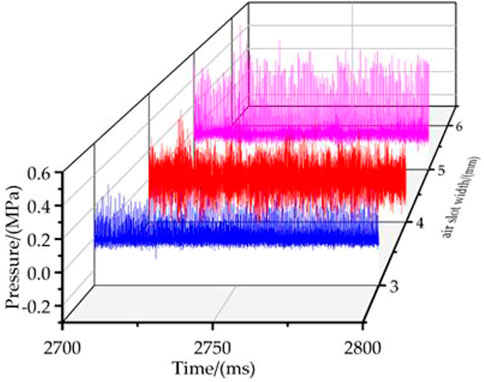
FIGURE 8. Comparison of pressure with different slot widths.
For the three operating conditions in this section, the pressure signals in the isolator after filtering were all ∼0 MPa without a clear pressure peak (Figure 9). The sensors in the isolator did not capture back pressure signals in the combustor. The experimental results showed that the designed intake structure effectively inhibited the back pressure of the detonation wave.
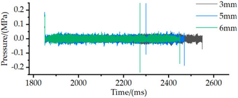
FIGURE 9. Comparison of pressure signals in the isolator.
The pressure signals of the P3 sensor under different air slot widths showed that the main frequencies were 1950, 1936, 1804, and 1700 Hz (Figure 10). The propagation velocity of the detonation wave corresponded to 1138.88, 1130.69, 1053.61, and 992.87 m/s .
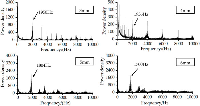
FIGURE 10. Comparison of FFT with different slot widths.
3.3 Influence of the equivalent ratio
The mass flow rate of the fuel was adjusted such that the reactant equivalent ratio was 1.0/1 and 1.1/1, and other parameters were consistent with the test conditions, as shown in Section 3.1; Table 2.

TABLE 2. Experimental parameters with different equivalent ratios.
When the mass flow rate of fuel was 88 g/s, the corresponding reactant equivalent ratio was 1.0/1. In this case, the detonation wave was successfully initiated in the combustor and operated for a period of 1963.7–2,428.0 ms (Figure 11). This was similar to test data when the equivalent ratio was 1.2/1, and the DDT process occurred in the ignition stage, with re-initiation proceeding in the flameout stage. The P1 sensor in the isolator did not detect the characteristic signal of the forward shockwave. In the self-sustained propagation stage of a detonation wave, the more complex propagation modes of double waves and multi-wave emerged.
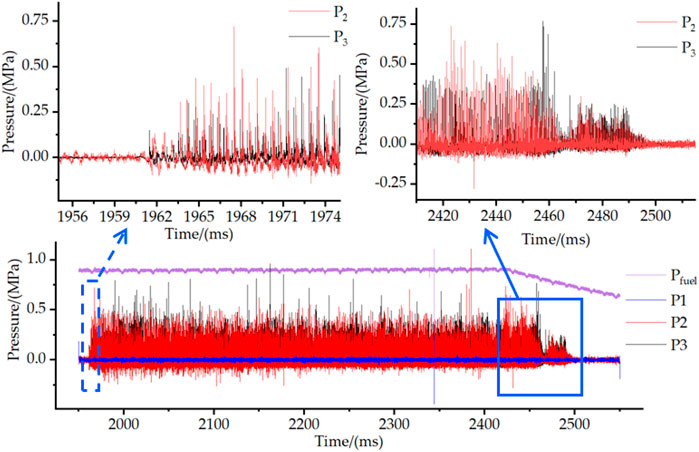
FIGURE 11. Results of operating at ER = 1.0 and lw = 4 mm.
Measured pressure changes in the combustor showed that the first peak represented the propagation frequency of the detonation wave, which was 1803 Hz, and the second peak at 2,965 Hz, the secondary frequency (Figure 12). The frequency and time distribution of P3 data was acquired after the original signal was processed by short-time Fourier transform (STFT). The marked spectrum line signified the main frequency with a value of 1812 Hz. In addition, there was a secondary main frequency band with a value of 2,960 Hz. The frequency and time variation in the flameout stage was observed (red-dotted circle).
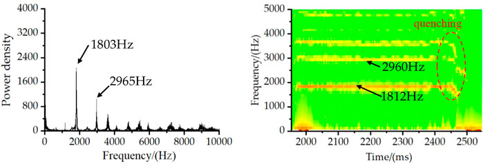
FIGURE 12. Results of FFT and STFT by P3 at ER = 1.0 and lw = 4 mm.
When the mass flow rate of fuel was increased to 97 g/s, the reactant equivalent ratio was increased to 1.1/1. The rotating detonation wave propagated from 1856.8 to 2,421.2 ms (Figure 13). The DDT process still existed in the ignition stage, while the phenomenon of pressure fluctuation occurred after re-initiation in the flameout stage. However, the intensity was too low to establish the detonation wave again. The fluctuation of pressure in the flameout stage indicated that there was still intermittent combustion reaction in the combustor after the fuel was turned off. The reason for this could be from fresh reactants filling at a lower height.
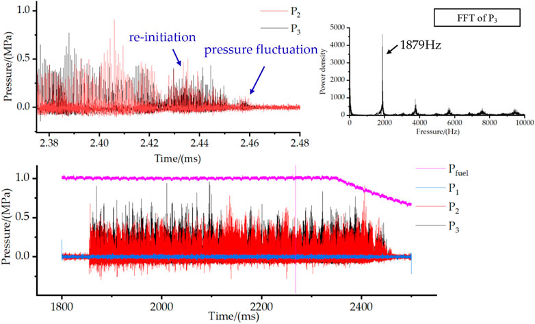
FIGURE 13. Results of operating at ER = 1.1 and lw = 4 mm.
When the RDE was operating, the propagation mode of the detonation wave was principally the single-wave mode, which was accompanied by the phenomenon of single–double wave conversion, double wave collision, and propagation direction conversion. The main frequency was 1879 Hz in the combustor (Figure 13).
The pressure comparison diagram elaborated on the P3 signals intercepted at different equivalent ratios during the period from 2000 to 2,100 ms. The pressure changes at equivalent ratios of 1.0/1, 1.1/1, and 1.2/1 were plotted (Figure 14, colored curves). Both the purple and red curves showed severe fluctuations, and pressure amplitudes were not stable, while the blue pressure curve was relatively stable. It was speculated that a change in the propagation mode of the detonation wave was the cause of these observations.
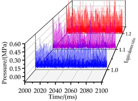
FIGURE 14. Comparison of pressure with different equivalent ratios.
3.4 Influence of the length of the RDC
The combustor was disassembled to shorten the combustor length to 80 mm, with other test conditions unchanged. The mass flow rate of the fuel was adjusted to 106 g/s, and the equivalent ratio was 1.2/1.
According to the analysis of pressure signals, the multi-wave collision mode was presented first after successful ignition. Then, the mode gradually changed from a single wave to homodromous double wave, and the process is shown in the local magnification diagram given in Figure 15. The maximum peak pressure at 1.42 MPa was measured by sensor P2 in the single-wave propagation stage, while the total pressure amplitude in the double-wave stage was lower, and the maximum pressure was only 0.53 MPa. In the local magnification curve of the double wave, the rotating detonation wave propagated in the form of two waves along the same direction. As the detonation wave continued to propagate, a new wave would be formed. At this time, the phenomenon of collision appeared intermingled and gradually evolved into the multi-wave collision mode. After the fuel valve was turned off, the detonation wave gradually decoupled and flamed out.
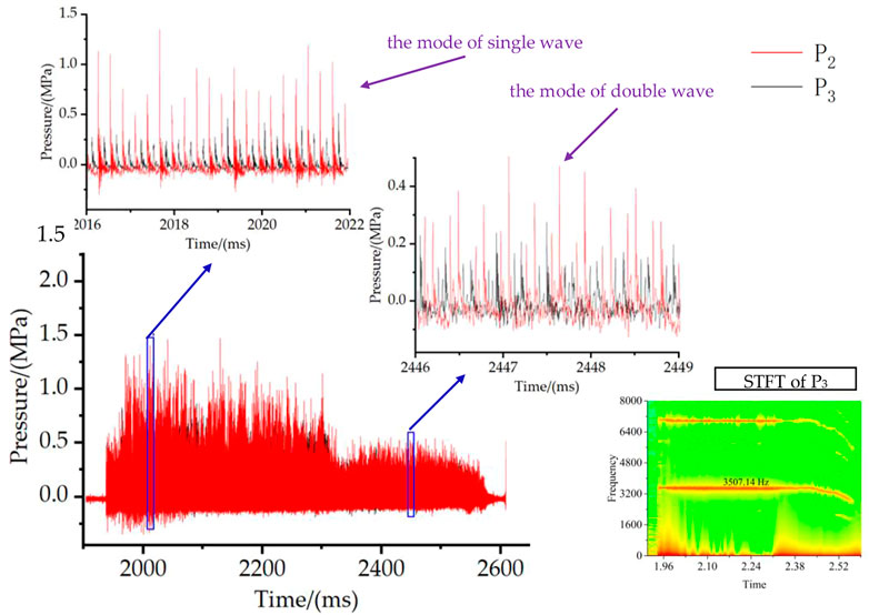
FIGURE 15. Results of operating at ER = 1.2, lw = 4 mm, and lc = 80 mm.
By processing the STFT of the original signals, it was calculated that the propagation frequency of the detonation wave was 3,507.14 Hz. The propagation velocity was 1024.16 m/s because the detonation wave in the double-wave mode propagated in the same direction. Compared with the longer combustor, the velocity slightly decreased, and as the velocity of the detonation wave was faster, the filling time of fresh reactants was compressed, and the filling height was reduced. Therefore, the detonation wave pressure decreased under a certain equivalent ratio, and the propagation mode changed from a single wave to a double wave. In the flameout stage, the reactant filling height was too low to support the successful initiation of the rotating detonation wave.
4 Conclusion
In this study, the detonation wave propagation in an RDC with high enthalpy air was experimentally examined. The air passed through the circle-to-ring isolator, and then, the fuel was mixed with the air at a vertical angle. The mixture was affected by the structure, with the flow direction changed to enter the combustor. The detonation wave was successfully generated in the combustor using the pre-detonator. Based on the test conditions of this study, the conclusions were as follows:
1) When the slot width of the air was changed from 3 to 5 mm, the pressure of the detonation wave was augmented with an increased slot width. However, when the width was broadened to 6 mm, the detonation wave propagated discontinuously.
2) When the slot width of the air was 4 mm and the combustor length 160 mm, the detonation wave was formed in the RDC at the equivalent ratios of 1.0/1, 1.1/1, and 1.2/1. The propagation modes of detonation waves were complex, including single and double waves. The complex phenomenon was observed, which included single–double wave conversion, double wave collision, and propagation direction conversion.
3) The average propagation velocity of the detonation wave was related to the slot width of the air, equivalent ratio, and combustor length. When the equivalent ratio was 1.2/1, the velocity of the detonation wave decreased with broader air slots from 3 to 6 mm. When the air slot was 4 mm, and the equivalent ratio increased from 1.0/1 to 1.2/1, the velocity of the detonation wave was gradually accelerated.
4) When the length of the combustor was changed from 160 to 80 mm, the propagation mode of the detonation wave changed. Initially, the detonation wave propagated as a single wave at 1130.69 m/s. Then, in the double-wave mode, the velocity was reduced to 1024.16 m/s. The reason for this was that the filling time and height of fresh reactants were decreased as velocity accelerated, leading to decreased detonation wave pressure. Re-initiation did not appear in the case of the shorter combustor, which was related to the filling process of reactants.
5) In all test conditions, no signal of the rotating back pressure was measured in the isolator. This indicated that the RDE inlet structure designed in this study could inhibit back pressure in the combustor.
Data availability statement
The original contributions presented in the study are included in the article/Supplementary Materials; further inquiries can be directed to the corresponding author.
Author contributions
SX: conceived the experimental design, conducted data analysis, and writing; XZ: built experimental systems and performed experimental data processing; JY and HM: provided overall ideas and performed data analysis; CZ and DL: guided the experimental operation.
Funding
This work was supported by the National Natural Science Foundation of China (12072163, 5210060296, and 11802134) and the National Defense Science and Technology Key Laboratory Foundation (HTKJ2020KL011004-1).
Acknowledgments
Throughout the writing of this paper, the authors acknowledge the great deal of support and assistance they have received. They particularly thank their teammates and professor for their wonderful collaboration and wise counsel. In addition, they would like to thank their parents and Yuge XZ for their patient support and sympathetic ear.
Conflict of interest
The authors declare that the research was conducted in the absence of any commercial or financial relationships that could be construed as a potential conflict of interest.
Publisher’s note
All claims expressed in this article are solely those of the authors and do not necessarily represent those of their affiliated organizations, or those of the publisher, the editors, and the reviewers. Any product that may be evaluated in this article, or claim that may be made by its manufacturer, is not guaranteed or endorsed by the publisher.
References
Bao-xing, L., Gui-yang, X., Chun-sheng, W., and Feng-qi, Z. (2021). Experimental investigation for effects of chamber width on rotating detonation engine with liquid fuel[J]. J. Propuls. Technol. 42 (2), 372–381. doi:10.13675/j.cnki.tjjs.190472
Dunn, I., Sosa, J., and Ahmed, K. A. (2020). Flowfield velocity measurements of a rotating detonation engine. Orlando: AIAA Scitech 2020 Forum 2020. doi:10.2514/6.2020-1176
Feng, W., Zheng, Q., Wang, X., Dong, X., Weng, C., Xiao, Q., et al. (2022). Effect of equivalent ratio on two-phase rotating detonation wave of kerosene-air[J]. ACTA ARMAMENTARII 2022 43(6):1304–1315. doi:10.12382/bgxb.2021.0352
Gao-yang, G. E., Yuan, M. A., Xia, Z. -j., Hou, S. -z., Ma, H., Deng, L., et al. (2022). Verification experimental of rotating detonation fueled by gasoline with high total temperature air[J]. J. Propuls. Technol. 43 (6), 200943. doi:10.13675/j.cnki.tjjs.200943
Hong-bo, H., Yan, Y., Zhang, F., Hong, L., and Chen, H. -Y. (2020). Experimental investigation on rotating detonation combustion with fuel-rich gases of kerosene[J]. J. Propuls. Technol. 41 (4), 881–888. doi:10.13675/j.cnki.tjjs.190407
Kawasaki, A., Inakawa, T., Kasahara, J., Goto, K., Matsuoka, K., Matsuo, A., et al. (2019). Critical condition of inner cylinder radius for sustaining rotating detonation waves in rotating detonation engine thruster[J]. Proc. Combust. Inst. 37 (3), 3461–3469. doi:10.1016/j.proci.2018.07.070
Liu, S. -J., Peng, H. -Y., Liu, W. -D., and Zhang, H. -L. (2020). Effects of cavity depth on the ethylene-air continuous rotating detonation[J]. Acta Astronaut. 166 (2020), 1–10. doi:10.1016/j.actaastro.2019.09.038
Meng, H., Xiao, Q., Feng, W., Wu, M., Han, X., Wang, F., et al. (2022). Air-breathing rotating detonation fueled by liquid kerosene in cavity-based annular combustor[J]. Aerosp. Sci. Technol. 122, 107407. doi:10.1016/j.ast.2022.107407
Tobias, J., Depperschmidt, D., Welch, C., Miller, R., Uddi, M., Agrawal, A. K., et al. (2019). OH* chemiluminescence imaging of the combustion products from a methane-fueled rotating detonation engine[J]. J. Eng. Gas Turbines Power. 141 (2), 021. doi:10.1115/gt2018-77255
Voitsekhovskii, B. V., Mitrofanov, V. V., and Topchiyan, M. E. (1969). Structure of the detonation front in gases (survey)[J]. Combust. Explos. Shock Waves 5 (3), 385–395. doi:10.1007/bf00748606
Wang, B., Qiao-feng, X., Wen, H. -c., Teng, H. -h., Zhang, Y.-n., and Zhou, L. (2021). Research progress of detonation engines[J]. J. Propuls. Technol. 42 (4), 721–737. doi:10.13675/j.cnki.tjjs.210109
Wang, C., Zheng, Y., Cai, J., Xiao, B., Liu, Y., and Le, J. (2022). Direct connected experimental research on hydrocarbon-fueled rotating detonation[J]. J. Exp. Fluid Mech. 36 (4), 1–9. doi:10.11729/syltlx20210086
Wang, D., Zhou, J., and Lin, Z. -y. (2017). Experimental investigation on operating characteristics of two-phase continuous rotating detonation combustor fueled by kerosene[J]. J. Propuls. Technol. 38 (2), 471–480. doi:10.13675/j.cnki.tjjs.2017.02.028
Wang, S., Wu, Y., Jin, D., Guo, G., Zhong, Y., and Yang, X. (2020). Effects of nozzles on performance of rotating detonation at different equivalent ratios[J]. Explos. Shock Waves 40 (10), 15–25. doi:10.11883/bzycj-2019-0481
Wang, Z. -c., Yan, Y., Wang, K., Zhao, M. -h., Zhu, Y. -y., and Fan, W. (2021). Effects of combustor width on propagation modes of rotating detonation waves utilizing liquid kerosene[J]. J. Propuls. Technol. 42 (4), 842–850. doi:10.13675/j.cnki.tjjs.200256
Xia, Z., Zhang, C., Wang, F., He, Y., Ma, H., Ge, G., et al. (2022). Propagation characteristics of hydrogen-air rotating detonation wave in disk-shaped combustors with different configurations[J]. Aerosp. Sci. Technol. 130, 107806. doi:10.1016/j.ast.2022.107806
Xue, S., Ying, Z., Hu, M., and Zhou, C. (2022). Experimental investigation on two-phase rotating detonation fueled by kerosene in a hollow directed combustor[J]. Front. Energy Res. 10. doi:10.3389/FENRG.2022.951177
Yuan, X., Jiang, L., Zhang, D., and Liu, S. (2021). Experimental Study on propagation mode of detonation wave in annular channel[J]. J. Rocket Propuls. 47 (6), 101–110.
Zhang, S. -J., Qiao-dong, B., Jia-xiang, H., Chun-sheng, F., and Chun-sheng, Z. (2022). Experimental study on propagation characteristics of rotating detonation combustion wave of hydrogen-rich gas[J]. J. Propuls. Technol. doi:10.13675/j.cnki.tjjs.210556
Zheng, Y. -s., Wang, C., Li, H. -b., Yue, M. -x., Le, J. -l., and Liu, Y. (2022). Free jet experimental research of hydrogen-air rotating detonation ramjet engine[J]. J. Propuls. Technol. 25. doi:10.13675/j.cnki.tjjs.210529
Zhou, S., Hu, M., Liu, C., and Zhou, C. (2018). Experimental investigation on the temperature and heat-transfer characteristics of rotating-detonation-combustor outer wall[J]. Int. J. Hydrogen Energy 42 (45), 21079–21089. doi:10.1016/j.ijhydene.2018.09.137
Keywords: direct connection test, rotating detonation, combustor, isolator, upstream shockwave
Citation: Xue S, Zhang X, Yang J, Liu D, Ma H and Zhou C (2023) Experimental study on the rotating detonation engine based on a gas mixture. Front. Energy Res. 11:1136156. doi: 10.3389/fenrg.2023.1136156
Received: 02 January 2023; Accepted: 02 March 2023;
Published: 27 March 2023.
Edited by:
Xiao Liu, Harbin Engineering University, ChinaReviewed by:
Banglin Deng, Shenzhen University, ChinaAntonio Paolo Carlucci, University of Salento, Italy
Copyright © 2023 Xue, Zhang, Yang, Liu, Ma and Zhou. This is an open-access article distributed under the terms of the Creative Commons Attribution License (CC BY). The use, distribution or reproduction in other forums is permitted, provided the original author(s) and the copyright owner(s) are credited and that the original publication in this journal is cited, in accordance with accepted academic practice. No use, distribution or reproduction is permitted which does not comply with these terms.
*Correspondence: Hu Ma, bWFodW9rb2tAMTYzLmNvbQ==