 Chengjie Li1
 Jiang Qin
- 1School of Energy Science and Engineering, Harbin Institute of Technology, Harbin, China
- 2Institute of Intelligent Ocean Engineering, Harbin Institute of Technology (Shenzhen), Shenzhen, China
- 3Chongqing Research Institute, Harbin Institute of Technology, Harbin, China
Solid oxide fuel cells (SOFC) have gradually become possible to be used in the aviation field because of their high efficiency and fuel flexibility. The number of internal combustion engines (ICE) that are already in use is large, which makes it difficult to completely abandon them in a short period. Hence, finding low-carbon alternative fuels is significant for the development of cleaner internal combustion engines. In this paper, different hybrid power systems configured with different fuels, i.e., hydrogen, methanol, liquid ammonia, isooctane, natural gas and gasoline, which consist of a solid oxide fuel cell and an internal combustion engine, are constructed to help find the optimal set of fuel and system structure by analyzing the power generation performance and weight of different systems. The results show that the hybrid power system with ammonia or methanol (except gasoline) as fuel presents the lowest actual fuel consumption rate (around 310 g/kWh). The hybrid power system with ammonia as fuel performs the highest power generation efficiency of 61.58%, and the corresponding power density is estimated at 0.556 kW/kg. In conclusion, the proposed system with ammonia as fuel has obvious advantages in fuel consumption rate, power generation efficiency, carbon emission reduction and fuel storage.
1 Introduction
Since the industrial revolution, the use of fossil fuels has promoted social progress and economic development. However, the use of fossil fuels will lead to carbon emissions, which will lead to climate change (such as the greenhouse effect, and sea-level rise). In 2019, human beings discharged 3.3 billion tons of carbon dioxide into the atmosphere (IEA, 2021). The carbon emissions from the aviation field account for about 3% of the global total carbon emissions (The international council on clean, 2013), and energy conservation and emission reduction is the inevitable choice for the sustainable development of the aviation field (European Commission, 2011).
To reduce aviation carbon emissions, The use of aviation alternative fuel and the innovation of power system have become the main direction of technological development. As a new type of power generation device, the fuel cell generates electric energy through the electrochemical reaction between fuel and oxygen, which avoids the limitation of the Carnot cycle and has the advantage of high efficiency (Zhang et al., 2010). Among several fuel cells, solid oxide fuel cells have many advantages, such as high energy conversion efficiency (40%–60%), wide fuel adaptability, no need for precious metals as catalysts, all solid state, modular assembly, near zero pollution et al. (Stambouli and Traversa, 2002; Greco et al., 2014; Jamil et al., 2015; Mahato et al., 2015; Grorge and Frank, 2017). As a power generation device, SOFC can use either traditional fossil fuel or hydrogen based fuel. The SOFC can have internal reforming reactions within it, so it can also utilize the fuel directly. Somano et al. (2021) Conducted a performance study of a tubular SOFC with biomass gas as fuel and showed that a power output of 200 W was achieved with 25 cells. Kupecki et al. (2017) Conducted a simulation study of a 1300 W direct methane SOFC and showed that the effect of internal reforming on the outlet temperature is significant when the current exceeds 22 A. Huang and Reimert (2011) Conducted an experimental study on the performance of ethane reforming in the SOFC anode channel and showed that the predicted and experimental values of the reforming model were in agreement with each other in terms of ethane conversion and product composition. The above studies show that SOFC has significant advantages in fuel adaptability. At the same time, the tail gas of SOFC contains unreacted fuel, which can form a hybrid power system with the heat engine to improve the efficiency of the power system (Buonomano et al., 2015). It is considered to be a promising power generation system.
At present, the fuels used in the research of SOFC hybrid power systems are mainly divided into gaseous fuel and liquid fuel. Among gaseous fuels, hydrogen is the most suitable for fuel cells. Hydrogen is considered one of the promising energy carriers because of its environmentally friendly characteristics (ContrerasYiğit et al., 1997). However, due to the special physical and chemical characteristics of hydrogen, it is in gaseous state under standard conditions and is very difficult to liquefy (boiling point −253°C, 0.1 MPa) (Hirscher et al., 2007). Therefore, hydrogen storage has become one of the key technical challenges restricting the development of hydrogen energy (Yadav and Xu, 2012). Another gaseous fuel is methane (FallahMahmoudiYari, 2018) or fuel gas with methane as the main component (Yari et al., 2016; ChoiAhnLee and Kim, 2019; Lv et al., 2019). As the simplest hydrocarbon fuel, the application of methane in aviation faces the same problem as that of hydrogen. Under standard conditions, methane presents a gaseous state and is not easy to liquefy (boiling point −160°C, 0.1 MPa). Compared with gaseous fuel, there are relatively few studies on using liquid fuel with convenient storage as SOFC system fuel. At present, the liquid fuels used in SOFC hybrid power systems mainly include fossil fuels such as diesel (Ezgi et al., 2013) and aviation kerosene (Liu et al., 2021), and new green fuels such as liquid ammonia (Meng et al., 2007) and alcohols (Choedkiatsakul et al., 2011). The effect of impurities in the fuel on the performance of SOFC has also been studied. Doyle et al. (2014) Studied the effect of toluene concentration on the performance of SOFC. The results showed that toluene up to 20 g/m3 would not have a negative impact on the performance of the cell. On the contrary, the content of available hydrogen was increased by reforming. Illathukandy et al. (2022) Investigated the effect of hydrogen chloride on the reforming performance within SOFC and showed that there was no negative effect on reforming or cell performance at 4, 8, and 12 ppm of hydrogen chloride in biogas, respectively. Papurello et al. (2021) Carried out an experimental study on the effect of trace compounds within the biogas on the performance of SOFC and showed that hydrochloric acid is detrimental to the performance of SOFC. The above results show that SOFC has a high tolerance to a wide range of impurities.
In the SOFC hybrid power system, the hybrid power system composed of SOFC and gas turbine (GT) was first proposed and studied. The SOFC/GT hybrid power system is used in ground power generation systems (Palsson et al., 2000; Zhao et al., 2011; Huang and Turan, 2020; Mohammad et al., 2022) and aviation power systems (Himansu et al., 2006; Aguiar et al., 2008; Jia et al., 2013; Fernandes et al., 2015). However, in the case of low power, the gas turbine is not as efficient as the internal combustion engine (Ward et al., 2018). Moreover, the research shows that the varied working condition performance of SOFC/GT hybrid power systems is poor (Chan et al., 2003). Therefore, in the field of ground distributed generation, some scholars have proposed SOFC/ICE hybrid power systems (Park et al., 2014), (Brauna et al., 2021). Natural gas is used as fuel. After the steam reforming reaction in the reformer, the fuel becomes hydrogen rich gas and enters SOFC for reaction, and the tail gas of SOFC enters the internal combustion engine for combustion. The results show that the efficiency of SOFC engine system is 59.5%, which is 7.8% and 0.9% higher than that of the simple SOFC system and SOFC/GT hybrid power system respectively. Kim et al. (2020) Builted a test-bed of the SOFC/ICE hybrid systems and carried out experimental research. The results show that when hydrogen is used as fuel, the efficiency of the hybrid power system reaches 55%. The above research shows that SOFC/ICE hybrid power system has excellent performance potential.
At present, the SOFC/ICE hybrid power system applied to ground distributed power generation focuses on using natural gas as fuel. At the same time, the system pays more attention to waste heat recovery, which leads to the complexity of the system. And the reforming mode of fuel adopts steam reforming, which requires a lot of water and heat. In the field of aviation power systems, there is no research on SOFC/ICE hybrid power system. The main technical problems faced by the application of SOFC/ICE hybrid power system in the aviation field can be concluded as: 1) Low temperature and pressure of ambient air at high altitude will reduce the performance of fuel cells; 2) Aircraft cannot carry excess water for fuel reforming; 3) The performance of alternative fuels such as electrofuels in SOFC/ICE hybrid power system is unknown.
Therefore, it is significant to study the optimization of alternative fuels and the SOFC/ICE system in aviation structure improvement. In this paper, methane and isooctane are selected as the alternative to natural gas (Jia et al., 2011) and gasoline (Kang et al., 2006), respectively, and the green fuels of hydrogen, methanol and liquid ammonia are also studied. Four types of SOFC/ICE hybrid power systems configured with different fuels are constructed. The main objective of this paper is to obtain the optimal set of fuel and system structures by modeling and analyzing. In addition, the effects on various power generation performances and the weight of different systems are investigated.
2 System description
2.1 Fuel types
Table 1 shows the situation of several common fuels (Department of Energy Hydrogen Program Plan, 2020), namely, high-pressure methane, high-pressure hydrogen, methanol, isooctane and liquid ammonia. Methanol and gasoline are liquid at room temperature. They have the advantages of high energy density and convenient storage. They have commonly used fuels in other power systems. Among them, methanol reforming is a good hydrogen storage carrier with low hydrogen production temperature (Bowers et al., 2007). The hydrogen content of ammonia is 17.6 wt%, without carbon and easy to liquefy (boiling point −33°C, 0.1 MPa) (Siddiqui et al., 2020). In the context of carbon neutralization, ammonia has ideal physicochemical properties as a clean fuel. Methane and hydrogen have low energy density in a gaseous state and are not easy to liquefy (CH4: Boiling point −160°C, 0.1 MPa; H2: Boiling point −253°C, 0.1 MPa). However, the storage technology of methane and hydrogen is constantly improving and is considered to be a promising fuel in the future. Different fuels will have a great impact on the performance of aviation SOFC/ICE hybrid power systems. Therefore, the performance of power systems with different fuels is studied in this paper.
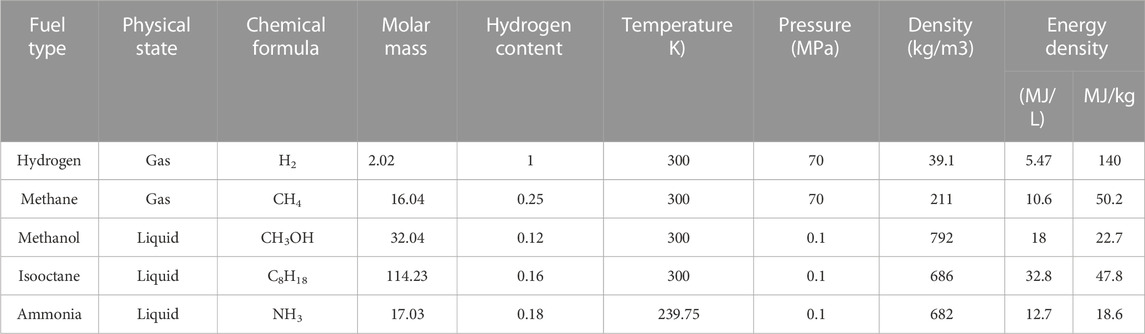
TABLE 1. Fuel properties (Colozza and Kohout, 2002).
2.2 System introduction
Figure 1 shows the layout diagram (a) and the temperature-entropy diagram (b) of the aviation SOFC/ICE hybrid power system. ICE is used as the bottom cycle of SOFC to improve energy utilization, and combined with a turbocharger to adapt to the impact of thin air at high altitudes. The thermodynamic process of the system is that the air is compressed, heated and pressurized by isentropic compression, enters the fuel cell after preheating, and the tail gas enters the internal combustion engine to complete the cycle, and then expands by the isentropic expansion of the turbine.
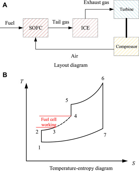
FIGURE 1. Scheme of the aviation SOFC/ICE hybrid power system. (A) Layout diagram. (B) Temperature-entropy diagram.
Figure 2 introduces the schematic diagram of the aviation SOFC/ICE hybrid power system with different fuels supply. They are methane (g), isooctane (l), hydrogen (g), methanol (l), and ammonia (l). The working principle of the system is that the air is heated and pressurized after passing through the turbocharger. Part of the air enters the reformer to participate in the reforming reaction, and the other part is preheated by the cathode tail gas of the solid oxide fuel cell and then enters the SOFC cathode. After the fuel is reformed into hydrogen rich gas in the reformer, which enters the SOFC anode an for electrochemical reaction to generate electric energy. SOFC anode tail gas and cathode tail gas are mixed and then sent to the internal combustion engine for combustion. After preheating the fuel, the exhaust gas pushes the turbocharger to work. According to the different ways and conditions of hydrogen release from different fuels, different hybrid power systems are constructed.
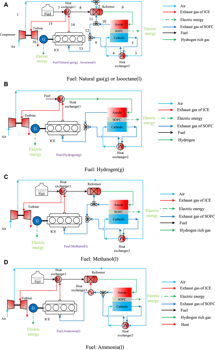
FIGURE 2. Schematic diagram of aviation SOFC/ICE hybrid power systems with different fuel supplies. (A): Natural gas(s) or Issooctane. (B): Hydrogen(g). (C): Methanol(l). (D): Ammonia(l).
Figure 2A shows the schematic diagram of aviation SOFC/ICE hybrid power systems with methane and isooctane as fuel. The pressurized air, preheated fuel and some anode tail gas an undergo autothermal reforming reaction in the reformer. Autothermal reforming can achieve a high hydrogen production rate without external heating, which is a promising reforming method. Anode recycling combined with autothermal reforming can solve the problem that water cannot be carried on the aircraft. Figure 2B shows the schematic diagram of the hybrid power system with hydrogen as fuel, eliminating the reformer and anode reflux mode. Figure 2C shows the hybrid power system with methanol as fuel. Due to the fast reaction rate of methanol temperatures, the air flow into the reformer is cancelled. Figure 2D shows the hybrid power system diagram with liquid ammonia as fuel. Compared with the original scheme, since ammonia is produced by cracking hydrogen, the injection of air and the circulation of tail gas is cancelled, but the anode tail gas needs to provide heat for the reformer.
3 Mathematics model
3.1 Model assumptions
Before the calculation and analysis of the SOFC/ICE hybrid power systems, several assumptions are set:
(1) Systems are in stable operation.
(2) Air is made up of 21% oxygen and 79% nitrogen, and the composition of other components in the air is ignored (Tarroja et al., 2009).
(3) The fuel reforming reaction in the system is in chemical equilibrium.
(4) The heat loss of components in the system is ignored (Zhu et al., 2020).
(5) Assuming that the performance of each SOFC cell is the same, the performance of the fuel cell stack is calculated (Chuahy and Kokjohn, 2019).
(6) The pressure drop in the system is not considered temporarily (Kim et al., 2020).
3.2 Reformer model
Autothermal reforming reaction occurs in the reactor, the air is provided by the compressor, and the steam is provided by the anode tail gas circulation. The reforming temperature is taken as the outlet temperature of the reformer. For isooctane, methane and methanol fuels, reforming products include methane, carbon monoxide, carbon dioxide, hydrogen and water. For ammonia fuel, the reforming products are nitrogen and hydrogen. The equilibrium state of the reforming reaction is solved by the chemical equilibrium software provided by NASA (Martinez et al., 2015a; Martinez et al., 2015b). To verify the accuracy of the reforming model, we built a fuel reforming test platform, as shown in Figure 3A. The experimental principle is that the fuel and water are first pumped into a preheater for preheating and then into a reformer where steam reforming takes place. The reformer is a quartz tube filled with catalyst and heated by a muffle furnace. The reformed gas is first condensed in a cooling tower and then the dry gas composition is measured using a gas chromatograph. Figure 3B is a comparison diagram of experimental data and model data of methane steam reforming. The reaction conditions are that the reaction temperature is set at 800°C, the reaction pressure is set at 1 atmospheric pressure, and the water carbon ratio is set at 1.5. It can be seen from Figure 3B that the hydrogen concentration of the model is a little higher than the experiment, and the CO concentration is a little lower than the experiment, but the overall error is small, and the reforming model can meet the calculation requirements.
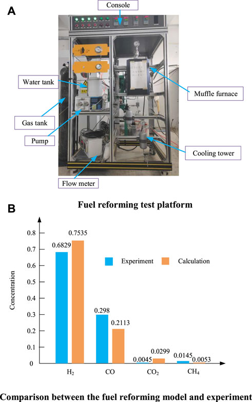
FIGURE 3. Fuel reforming test platform and methane steam reforming results. (A) Fuel reforming test platform. (B) Comparison between the fuel reforming model and experiment.
3.3 SOFC model
The SOFC model in this paper adopts the one-dimensional DIR (direct internal reforming) SOFC model (Ho et al., 2009), By dividing the structure of SOFC and discretizing it along the gas flow path, the distribution of temperature, material composition and other parameters along the path can be obtained by solving the physical parameters of each point.
The gas behind the reactor flows into the SOFC anode channel, which is mainly composed of methane, hydrogen, carbon monoxide, carbon dioxide, water vapor and nitrogen. With the progress of the hydrogen electrochemical reaction, the methane in the anode channel undergoes a reforming reaction with steam under the action of the catalytic layer to generate hydrogen. At the same time, the by-product carbon monoxide also has a displacement reaction with steam, as shown in Eqs 1–3. One dimensional SOFC model includes a mass conservation model, energy conservation model and electrochemical model. The mass conservation model ensures the conservation of matter, as shown in Eq. 4. The energy in SOFC is mainly represented by the generation and transmission of heat. The energy conservation equation is shown in Eq. 5. The electrochemical model is the calculation model of fuel cell output voltage, current and various polarization losses. The output voltage of the fuel cell is equal to Nernst’s electromotive force to eliminate polarization loss. Polarization loss mainly includes concentration polarization loss, ohmic polarization loss and activation polarization loss. The calculation formula is shown in Eqs 6–11. Table 2 shows the parameters involved in SOFC model. The fuel utilization and working voltage designed in this paper are within the normal value range of SOFC hybrid power systems (Pirkandi et al., 2012).
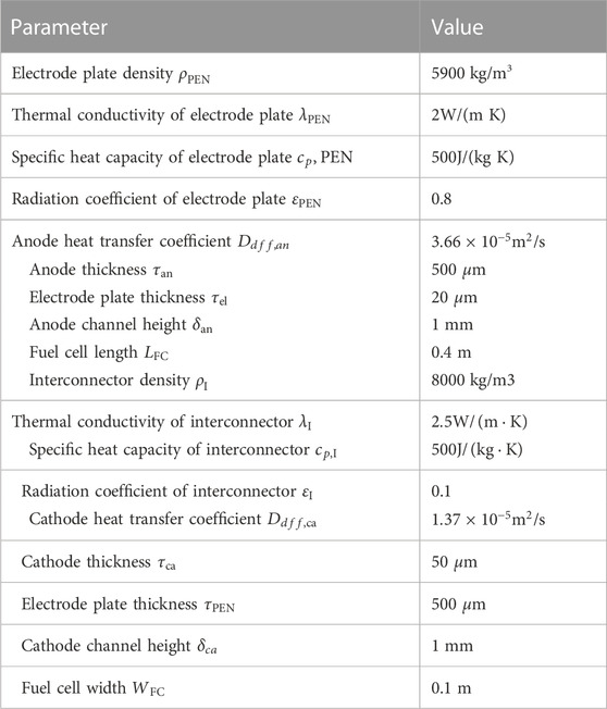
TABLE 2. Fuel cell model parameters.
In order to verify the accuracy of the fuel cell model, the calculation results of the model were compared with the experimental data in the literature (Zhao and Virkar, 2005). The operating temperature of SOFC is 1073.5 K, and the fuel is 97% hydrogen and 3% water by volume, and the results are shown in Figure 4. As can be seen from Figure 4, the error of the model is very small and can be used for systematic calculation.
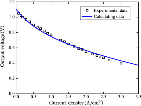
FIGURE 4. Diagram of electrochemical model validation results for fuel cells.
3.4 Internal combustion engine model
The internal combustion engine model in this paper adopts the constant volume cycle model, which believes that hydrogen and hydrocarbon fuels can be fully burned (Choi et al., 2018). The combustion degree of carbon monoxide is fitted according to the experimental data in the literature. The fitting formula is shown in Eq. 12. The cycle includes four processes: isentropic compression process (1-2), isochoric combustion process (2-3), isentropic expansion process (3-4) and isochoric exhaust process (4-1).
The effective efficiency of the internal combustion engine is shown in Eq. 13.
Table 3 shows the comparison between the model calculation results and the experimental results of the methanol internal combustion engine. The experimental data of methanol internal combustion engine is measured in the laboratory. It can be seen from Table 3 that the error between experimental data and calculated data is relatively small, which can meet the requirements of numerical calculation.
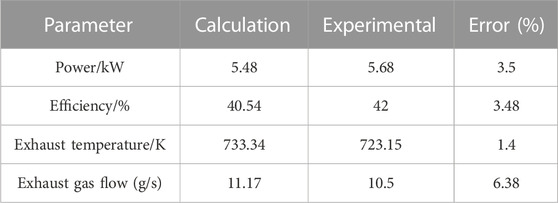
TABLE 3. Comparison between experimental data and calculated data.
3.5 Heat exchanger model
In this paper, the effectiveness method is used to model the heat exchanger model. The expression of effectiveness is shown in Eq. 14.
Meanwhile, the simultaneous energy conservation equation is shown in Eq. 15:
When calculating, usually given the inlet temperature of the high-temperature fluid and the inlet temperature of the low temperature fluid, the outlet temperature of high-temperature fluid and the outlet temperature of low temperature fluid can be calculated from the above two equations.
3.6 Turbine and compressor model
The compressor adopts an isentropic compression model and the turbine adopts an isentropic expansion model. The outlet temperature of the compressor is shown in Eq. 16. The power consumption of the compressor is the product of air flow, specific heat capacity and temperature difference. The specific formula is shown in Eq. 17. The turbine outlet temperature is calculated by using the power consumption characteristic of the compressor provided by the turbine, and then the turbine outlet pressure is calculated. The specific calculation formula is shown in Eqs 18, 19.
3.7 Mass modle
The mass models of turbocharger, SOFC, ICE, heat exchanger and reformer in hybrid power system will be introduced. SOFC technology development is not yet mature, especially in the power density is far lower than the current aero-engine. Countries are also making technological breakthroughs for the application of SOFC in the aviation field. At present, the solid oxide fuel cell developed by JAXA has advanced performance (Hashimoto et al., 2019a), (Hashimoto et al., 2019b), and its power density reaches 1.2 kW/kg. The mass of the solid oxide fuel cell in this paper is determined by the power density. However, it is a conservative estimation. The power density of the solid oxide fuel cell in this paper is 0.6575 kW/kg (Cirigliano et al., 2017).
The turbocharger in this system adopts the form of centrifugal compressor driven by centripetal turbine. The mass of centrifugal compressor is related to inlet mass flow and pressure ratio, while the mass of centripetal turbine is related to speed and expansion ratio. The turbocharger mass in this paper is obtained by fitting the data in the literature (Tornabene et al., 2005).
The mass of internal combustion engine is positively correlated with power. In this paper, the power density of internal combustion engine is selected as 1.14 kW/kg by referring to the power weight ratio of (Austria Rotax, 2022) and (Germany Limbach, 2022). The power of the generator is selected as 10.9 kW/kg by reference (Golovanov et al., 2021).
The heat exchanger is an important part of the system, mainly including preheating fuel, preheating cathode air of fuel cell and heating reactor. The material of the heat exchanger is SiC, and the heat exchange coefficient is 40 W/(m2˙K). The mass calculation formula of heat exchanger is shown in Eq (23), (Collins et al., 2020).
The reformer structure is based on the tubular reactor with length diameter ratio of 2 proposed in the literature. The reformer mass is related to space velocity and reactant mass flow (Tornabene et al., 2005). The mass of the reformer in this paper is calculated according to the formula, as shown in Eq. 24.
3.8 Solution method
The calculation flow of the program is shown in Figure 5. Firstly, the input parameters of the hybrid power system are given, including flight Mach number, altitude, pressure ratio and so on. After the calculation of intake air and compressor, start to give an initial value of SOFC output parameters into the mixer, and then calculate the reformer and SOFC successively and iterate circularly until the convergent anode reflux rate data is obtained. Next, the reforming equation and the electrochemical equation and energy conservation equation of the fuel cell are solved to obtain the performance parameters of the fuel cell, including the exhaust gas composition, output voltage, power and efficiency of the fuel cell. Then calculate the heat exchanger, internal combustion engine and turbine, and finally get the performance of the hybrid power system.
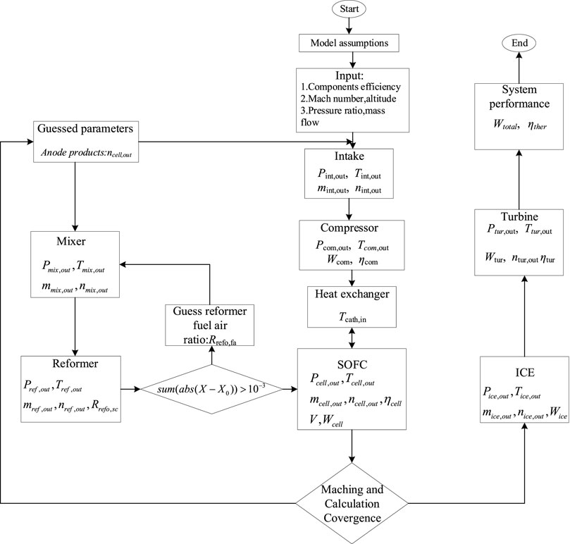
FIGURE 5. SOFC/ICE hybrid power system modeling flow chart.
4 Results and discussion
4.1 Working conditions
In order to study the power generation efficiency of hybrid power system under design conditions, some parameters of hybrid power system need to be selected, including excess air coefficient, fuel utilization and so on. Figure 6 shows the variation trend of the maximum temperature gradient in the fuel cell with excess air coefficient. As is shown in Figure 6, the temperature gradient in the fuel cell decreases with the increase of excess air coefficient. Hence, the value of excess air coefficient is set as 8 to reduce the temperature gradient of SOFC. And other given parameters of the hybrid power system are shown in Table 4. The fuel utilization rate of SOFC is assumed to 0.75 and the average current density is assumed as 5000 A/m2 (Liu et al., 2021) Moreover, due to the thin fuel concentration at the inlet of internal combustion engine, the HCCI combustion strategy (Park et al., 2014) is adopted, and the high compression ratio is selected as 15.
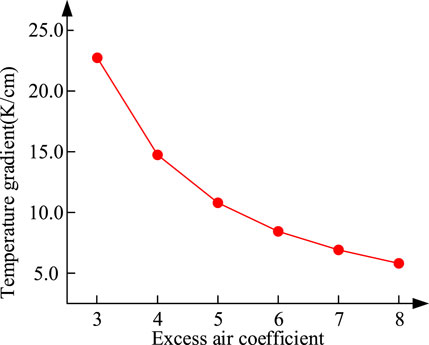
FIGURE 6. Trend diagram of maximum temperature gradient with excess air coefficient.
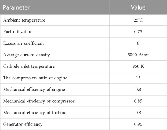
TABLE 4. Hybrid power system parameters (Liu et al., 2021), (Park et al., 2014).
4.2 Performance comparisons
Table 5 shows the calculation results of the hybrid power systems with five fuels. The flow of fuel is set as 1 mol/s. The reforming temperature is set as 850 K due to the heating demand of the ammonia cracking process, and the fuel cell exhaust gas can be recovered and utilized during this process. CH3OH utilizes the tail gas from anode reflux, and the reforming temperature of methanol is set as 900 K. Similarly, CH4 and C8H18 also use the tail gas of anode reflux, and the reforming temperature of methanol is set as 950 K.

TABLE 5. Calculation results of hybrid power system.
It can be seen from Table 5 that the SOFC/ICE hybrid power system using ammonia as fuel has the highest power generation efficiency, and the power generation efficiency of CH4 and C8H18 is low because the heat of ammonia cracking hydrogen production is provided by the fuel cell tail gas, which makes full use of the heat in the system, resulting in less heat loss in the tail gas and higher power generation efficiency., which is due to the use of autothermal reforming. On the one hand, it does not make full use of heat, resulting in large heat loss in the tail gas. On the other hand, it increases the supply of air and power consumption.
Figure 7 shows the comparison of fuel consumption and carbon emissions of hybrid power systems with different fuels. Among them, the mass of H2 and CH4 storage device is considered, and the mass density of hydrogen storage is 6% (The, 2015), CH4 is converted according to the density of H2 under the same pressure, and the storage mass density is 32.4%. The calculation formulas of fuel consumption rate and carbon emission are shown in Eqs 25, 26.
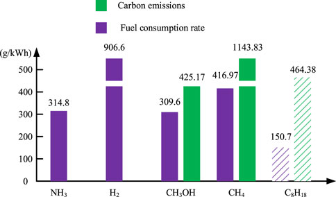
FIGURE 7. Performance of the SOFC/ICE fueled by different fuels.
As can be seen from Figure 7, the fuel consumption rate of traditional fossil fuel C8H18 is the lowest. It is liquid at room temperature and has high calorific value. However, the carbon emission of hydrocarbon fuels is too high. At the same time, as a non-renewable fuel, fossil fuels need to find suitable alternative fuels. Due to the characteristics of gaseous storage, the fuel consumption rate and carbon emission index of CH4 are not dominant. In terms of carbon emission indicators, H2 is in line with the vision of zero carbon fuel, but its actual fuel consumption is very high due to the immature hydrogen storage technology and the low mass density of hydrogen storage. Among the new alternative fuels, NH3 and CH3OH have the same fuel consumption rate index, but CH3OH does not meet the vision of green aviation because it may produce carbon emissions equivalent to hydrocarbon fuel when it is used as fuel. To sum up, NH3 is a fuel suitable for SOFC/ICE hybrid power systems. It can be stored in liquid state with zero carbon emission. At the same time, no nitrogen oxides can be produced in the system.
Figure 8 shows the actual output voltage of fuel cells in these systems. The fuel cell with H2 as fuel has the highest output voltage because of the high concentration of hydrogen. The output voltage of the fuel cell using CH3OH as fuel is the lowest because the hydrogen concentration in the methanol reforming gas is low. At the same time, due to the reduction of the reforming temperature of the methanol reformer, the inlet temperature of the fuel cell is low, resulting in the low output voltage. Due to autothermal reforming, systems with CH4 and C8H18 perform lower hydrogen content in reforming gas, larger concentration polarization and lower output voltage than H2 and NH3.
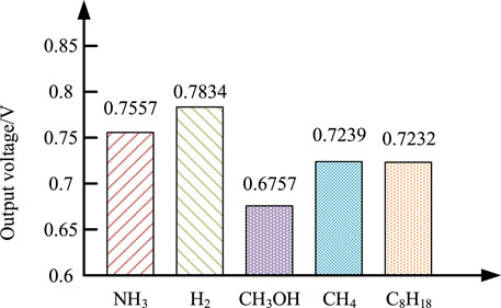
FIGURE 8. Fuel cell voltage VS fuel type.
To compare the performance of different fuels in the hybrid power system and study the variation law of parameters, there are many parameters involved in the hybrid power system, one is the parameter affecting the physical properties of the working medium, the other is the parameter affecting the fuel flow distribution of fuel cell and internal combustion engine. The effects of fuel utilization, pressure ratio, altitude, fuel cell operating temperature and reforming temperature on the hybrid power system are discussed in the following section.
4.3 Effect of parameters on system performance
Figure 9 shows the effect of various parameters on system performance. Figure 9A shows the efficiency variation of hybrid power systems with various fuel utilization rate under different fuel supplies. It can be seen from Figure 9A that the efficiency of the hybrid power system with NH3 and H2 as fuel increases with the increase of fuel utilization, and the efficiency of the hybrid power system with CH4 and C8H18 as fuel first increases and then decreases. Such a phenomenon is because the hybrid power systems (Figure 2A) with CH4, C8H18, and CH3OH as fuel have anode cycles. Hence, the actual fuel utilization is higher than the set fuel utilization. When the fuel utilization is too high, the fuel flow allocated to the internal combustion engine is seriously insufficient.
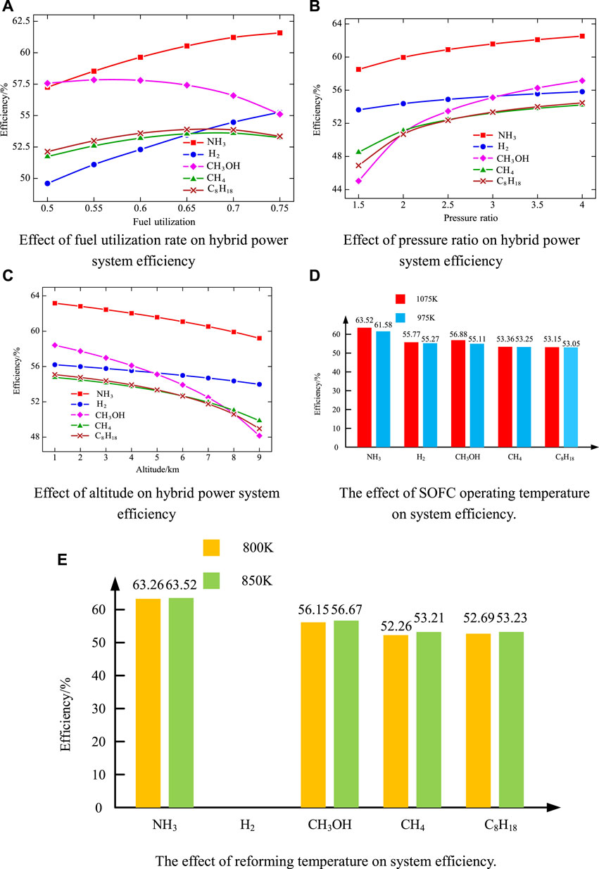
FIGURE 9. Effect of parameters on system efficiency. (A) Effect of fuel utilization rate on hybrid power system efficiency. (B) Effect of pressure ratio on hybrid power system efficiency. (C) Effect of altitude on hybrid power system efficiency. (D) The effect of SOFC operating temperature on system efficiency. (E) The effect of reforming temperature on system efficiency.
Figure 9B shows the efficiency variation of the hybrid power systems with different pressure ratio under different fuel supplies. It can be seen from Figure 9B that the efficiency of hybrid power systems increases with the increase in pressure ratio., regardless of the fuel type. This is because the change in the pressure ratio mainly affects the physical properties of the air, and then affects the fuel cell. When the working pressure of the fuel cell increases, the output voltage and power density will increase, and then the output power will increase.
Figure 9C shows the efficiency variation of hybrid power systems with different altitude under different fuel supplies. With the increase in the height, the thermal efficiency of the hybrid system gradually decreases, regardless of the fuel type. This is because the higher the height, the lower the temperature and pressure of the ambient air. Therefore, the efficiency of the fuel cell and the whole hybrid system is reduced accordingly.
Figure 9D shows the efficiency of the hybrid power systems when SOFC works at 975 K and 1075 K. It can be seen from Figure 9D that the hybrid power systems have higher efficiency when the SOFC work at the higher temperature of 1075 K because of the increasing voltage of the fuel cell. Although the lift of the working temperature reduces the open circuit voltage of the fuel cell, it reduces the internal resistance of the fuel cell and increases the output voltage of the fuel cell. Thus, the output power of the fuel cell and the system efficiency is improved.
Figure 9E shows the efficiency of the system when the fuel reforming temperature is 800 and 850 K (except hydrogen) (the working temperature of the fuel cell is 1075 K, and other parameters are consistent with the design conditions). As is shown in Figure 9E, the efficiency of the system is relatively high when the reforming temperature of the fuel is 850 K. This is because the higher the reforming temperature is, the better the hydrogen production rate is. At the same time, the anode inlet temperature of the fuel cell performs high, which is close to the working temperature of the fuel cell, resulting in a small temperature gradient. And the high inlet temperature of fuel cell helps to improve the efficiency of fuel cell.
4.4 Hybrid power system mass analysis
Through the above analysis, the ammonia SOFC/ICE system (namely, the hybrid power system taking ammonia as the fuel) can achieve high efficiency and zero carbon emission. Therefore, the mass of each component in the ammonia SOFC/ICE system should be studied to evaluate the feasibility for the aviation application. The output power of this ammonia SOFC/ICE system is calculated in accordance with Section 4.2.
Direct ammonia fuel cell (NH3 is directly used in SOFC without decomposition) is not used in this system, although it can remove an ammonia decomposition hydrogen production reactor and reduce the mass of the system. This is because the direct ammonia fuel cell will have problems such as anode degradation and catalyst failure (Wan et al., 2021). Producing hydrogen by ammonia decomposition is a convenient way to obtain hydrogen, because it has only one fuel flow path, and the reforming of hydrocarbon steam has multiple steps (Chiuta et al., 2013).
According to literature (Ji et al., 2021), the auxiliary of pipes, wires, controllers and other components in the hybrid power system accounts for 10% of the mass of main components of system.
The total mass of the ammonia SOFC/ICE system reaches 350.328 kg, and its power density is about 0.556 kW/kg. Figure 10 shows the mass distribution of each component in the ammonia SOFC/ICE system. It can be seen that the mass of SOFC accounts for most of the engine. Therefore, reducing the mass of SOFC, that is, improving the power density of SOFC, is an important research direction of SOFC application in the aviation field. In addition, how to reduce the use of heat exchangers or improve the heat exchange efficiency is also an important research work.
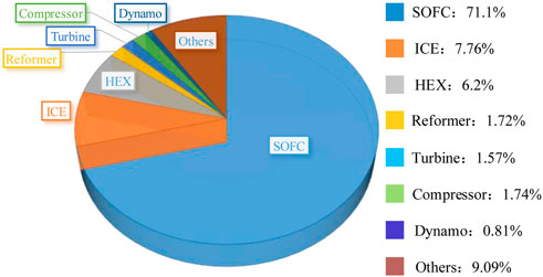
FIGURE 10. Mass of the devices in the ammonia SOFC/ICE system.
5 Conclusion
This paper studies the performance and parameter variation law of aviation SOFC/ICE hybrid power system with different fuel supplies, investigates the quality of hybrid power systems based on ammonia fuel, and draws the following conclusions:
1. Under design conditions, the SOFC/ICE hybrid power systems based on ammonia fuel has the highest power generation efficiency of 61.58%, This is because the SOFC/ICE hybrid power system with ammonia as fuel can make full use of the heat of the system and does not need autothermal reforming, which reduces the fuel consumption. The SOFC/ICE hybrid power system based on isooctane fuel has the lowest fuel consumption rate of 150.7 g/kWh, This is because isooctane has high calorific value and liquid state under standard conditions. The hybrid power system based on ammonia fuel and hydrogen supply has no carbon emission.
2. The analysis results of parameter influence law show that there is an optimal fuel utilization rate in the hybrid power system with different fuel supply, which makes the efficiency of the system the highest. The efficiency of hybrid power system increases with the increase of pressure ratio. The efficiency of hybrid power system decreases with the increase of working altitude, increases with the increase of fuel cell working temperature, and increases with the increase of reforming temperature
3. Under design conditions, the power density of hybrid power system based on ammonia fuel supply is estimated, and the result is 0.556 kW/kg. The mass of SOFC accounts for 70% of the hybrid power system. Improving the power density of SOFC is an important research direction to improve the power density of hybrid power system.
4. The main reason for the different efficiency of hybrid power systems with different fuel supply is the difference of hydrogen generation mode, which affects the utilization of heat and fuel consumption in the system. The main factors affecting the system quality is the complexity of the system and the power density of each component.
In general, under the requirements of aviation carbon emission reduction, ammonia, as a zero carbon fuel, is a suitable fuel for SOFC/ICE hybrid power system. However, this paper does not consider the comparison of carbon emission reduction effects of various fuels in the whole life cycle, and does not conduct parameter optimization research on SOFC/ICE hybrid power system. Next, we will conduct research on system configuration optimization and parameter optimization of SOFC/ICE hybrid power system based on ammonia fuel. Further, carry out the experimental research of ammonia decomposition hydrogen production combined with SOFC.
Data availability statement
The original contributions presented in the study are included in the article/supplementary material, further inquiries can be directed to the corresponding author.
Author contributions
CL: Formal analysis, Conceptualization, Validation, Writing- Original draft ZW: Supervision, Investigation, Validation, Resources HL: Visualization, Software JQ: Writing- Reviewing and Editing LW: Methodology, Investigation
Conflict of interest
The authors declare that the research was conducted in the absence of any commercial or financial relationships that could be construed as a potential conflict of interest.
Publisher’s note
All claims expressed in this article are solely those of the authors and do not necessarily represent those of their affiliated organizations, or those of the publisher, the editors and the reviewers. Any product that may be evaluated in this article, or claim that may be made by its manufacturer, is not guaranteed or endorsed by the publisher.
References
Aguiar, P., Brett, D., and Brandon, N. (2008). Solid oxide fuel cell/gas turbine hybrid system analysis for high-altitude long-endurance unmanned aerial vehicles. Int. J. Hydrogen Energy 33 (23), 7214–7223. doi:10.1016/j.ijhydene.2008.09.012
Bowers, B. J., ZhaoJ, L., Ruffo, M., Khan, R., Dattatraya, D., Dushman, N., et al. (2007). Onboard fuel processor for PEMfuel cell vehicles[J]. Int. J. Hydrogen Energy 32 (10-11), 1437–1442.
Brauna, R. J., Mundhwaa, M., Floerchinger, G., Sullivan, N. P., Vincent, T., Danforth, R., et al. (2021). Development of a high-efficiency, low-cost hybrid SOFC/internal combustion engine power generator. ECS Trans. 103 (1), 221–230. doi:10.1149/10301.0221ecst
Buonomano, A., Calise, F., d’Accadia, M. D., Palombo, A., and Vicidomini, M. (2015). Hybrid solid oxide fuel cells–gas turbine systems for combined heat and power: A review. Appl. Energy 156, 32–85. doi:10.1016/j.apenergy.2015.06.027
Chan, S. H., Ho, H. K., and Tian, Y. (2003). Modelling for part-load operation of solid oxide fuel cell–gas turbine hybrid power plant. J. Power Sources 114 (2), 213–227. doi:10.1016/s0378-7753(02)00613-4
Chiuta, S., Everson, R. C., Neomagus, H., van der Gryp, P., and Bessarabov, D. G. (2013). Reactor technology options for distributed hydrogen generation via ammonia decomposition: A review. Int. J. Hydrogen Energy 38 (35), 14968–14991. doi:10.1016/j.ijhydene.2013.09.067
Choedkiatsakul, I., Charojrochkul, S., Kiatkittipong, W., Wiyaratn, W., Soottitantawat, A., Arpornwichanop, A., et al. (2011). Performance improvement of bioethanol-fuelled solid oxide fuel cell system by using pervaporation. Int. J. Hydrogen Energy 36 (8), 5067–5075. doi:10.1016/j.ijhydene.2011.01.016
Choi, W., Kim, J., Kim, S., Oh, S., and Song, H. H. (2018). Experimental study of homogeneous charge compression ignition engine operation fuelled by emulated solid oxide fuel cell anode off-gas. Appl. Energy 229, 42–62. doi:10.1016/j.apenergy.2018.07.086
Choi, B. S., Ahn, J. H., Lee, J. H., and Kim, T. S. (2019). A comparative performance analysis of a solid oxide fuel cell and gas turbine combined cycles with carbon capture technologies. J. Mech. Sci. Technol. 33 (3), 1463–1475. doi:10.1007/s12206-019-0248-7
Chuahy, F. D. F., and Kokjohn, S. L. (2019). Solid oxide fuel cell and advanced combustion engine combined cycle: A pathway to 70% electrical efficiency. Appl. Energy 235, 391–408. doi:10.1016/j.apenergy.2018.10.132
Cirigliano, D., Frisch, A. M., Liu, F., and Sirignano, W. A. (2017). Diesel, spark-ignition, and turboprop engines for long-duration unmanned air flights. Propul. Power 34, 878–892. doi:10.2514/1.b36547
Collins, J. M., Mclarty, D., and Yan, J. (2020). All-electric commercial aviation with solid oxide fuel cell-gas turbine-battery hybrids[J]. Applied Energy 265, 114787.
Colozza, A. J., and Kohout, L. (2002). Hydrogen storage for aircraft applications overview. Brook Park, Ohio: Analex Corporation.
ContrerasYiğit, A. S., Özay, K., and Veziroğlu, T. N. (1997). Hydrogen as aviation fuel: A comparison with hydrocarbon fuels. Int. J. Hydrogen Energy 22 (10–11), 1053–1060. doi:10.1016/s0360-3199(97)00008-6
Doyle, A, Tygue S., Dehouche, Z., Aravind, P., Liu, M., and Stankovic, S. (2014). Investigating the impact and reaction pathway of toluene on a SOFC running on syngas. Int. J. Hydrogen Energy 39 (23), 12083–12091. doi:10.1016/j.ijhydene.2014.05.148
European Commission (2011). Flightpath 2050: Europe’s vision for aviation-report of the high level group on aviation research. Report of the high level group on aviation research. Luxembourg: European Commission. Available at:https://ec.europa.eu/transport/sites/transport/files/modes/air/doc/flightpath2050.pdf.
Ezgi, C., Oban, M. T., and Selvi, O. (2013). Design and thermodynamic analysis of an SOFC system for naval surface ship application[J]. J. Fuel Cell Sci. Technol. 10 (3), 031006.
FallahMahmoudiYari, M. S. M. (2018). A comparative advanced exergy analysis for a solid oxide fuel cell using the engineering and modified hybrid methods. Energy Convers. Manag. 168, 576–587. doi:10.1016/j.enconman.2018.04.114
Fernandes, A., Woudstra, T., and Aravind, P. V. (2015). System simulation and exergy analysis on the use of biomass-derived liquid-hydrogen for SOFC/GT powered aircraft. Int. J. Hydrogen Energy 40, 4683–4697. doi:10.1016/j.ijhydene.2015.01.136
Golovanov, D., Gerada, D., Sala, G., Degano, M., Trentin, A., Connor, P. H., et al. (2021). 4MW class high power density generator for future hybrid-electric aircraft[J]. IEEE Transactions on Transportation Electrification. doi:10.1109/TTE.2021.3068928
Greco, A., Littwin, R., Costamagna, P., and Magistri, L. (2014). Reformer faults in SOFC systems: Experimental and modeling analysis, and simulated fault maps. Int. J. Hydrogen Energy 39, 21700–21713. doi:10.1016/j.ijhydene.2014.09.063
Grorge, N. P., and Frank, A. C. (2017). Thermodynamic analysis of biogas fed solid oxide fuel cell power plants. Renew. Energy 108, 1–10. doi:10.1016/j.renene.2017.02.043
Hashimoto, S., Hirota, T., Suzuki, K., Namioka, T., Ito, H., Miyata, R., et al. (2019). Material development strategy of lightweight solid oxide fuel cells for airplane system electrification. ECS Trans. 91 (1), 311–318. doi:10.1149/09101.0311ecst
Hashimoto, S., Miyata, R., Yashiro, K., and Kobayashi, K. (2019). in A New Development Strategy of Light Wight Solid Oxide Fuel Cells for Electrified Airplane System[C]AIAA Propulsion and Energy 2019 Forum, 4470. doi:10.2514/6.2019-4470
Himansu, A., Freeh, J. E., Syeffenjr, C. J., Tornabene, R. T., and Wang, X. Y. J. (2006). Hybrid solid oxide fuel cell/gas turbine system design for high altitude long endurance aerospace missions [C]. Irvine: 4th International ASME Conference on Fuel Cell Science, Engineering and Technology.
Hirscher, L. D., Lamaridarkrim, F., and Hirscher, M. (2007). Metal hydride materials for solid hydrogen storage: A review☆. Int. J. Hydrogen Energy 32 (9), 1121–1140. doi:10.1016/j.ijhydene.2006.11.022
Ho, T. X., Kosinski, P., Hoffmann, A. C., and Vik, A. (2009). Numerical analysis of a planar anode-supported SOFC with composite electrodes. Int. J. Hydrogen Energy 34 (8), 3488–3499. doi:10.1016/j.ijhydene.2009.02.016
Huang, Y., and Turan, A. (2020). Mechanical equilibrium operation integrated modelling of hybrid SOFC – GT systems: Design analyses and off-design optimization. Energy 208, 118334. doi:10.1016/j.energy.2020.118334
Huang, X., and Reimert, R. (2011). Investigations on gas-phase reactions of ethane under SOFC conditions: An experimental and modeling study. Fuel 90 (2), 689–694. doi:10.1016/j.fuel.2010.10.001
Illathukandy, Biju, Saadabadi, S. A., Kuo, P. C., Wasajja, H., Lindeboom, R. E., Vijay, V., et al. (2022). Solid oxide fuel cells (SOFCs) fed with biogas containing hydrogen chloride traces: Impact on direct internal reforming and electrochemical performance. Electrochimica Acta 433, 141198. doi:10.1016/j.electacta.2022.141198
The international council on clean. (2013). The international council on clean transportation 2021.CO2 EMISSIONS FROM COMMERCIAL AVIATION: 2018.
Jamil, S. M., Othman, M. H. D., Rahman, M. A., Jaafar, J., Ismail, A., and Li, K. (2015). Recent fabrication techniques for micro-tubular solid oxide fuel cell support: A review. J. Eur. Ceram. Soc. 35, 1–22. doi:10.1016/j.jeurceramsoc.2014.08.034
Ji, Z., Qin, J., Cheng, K., Liu, H., Zhang, S., and Dong, P. (2021). Design and performance of a compact air-breathing jet hybrid-electric engine coupled with solid oxide fuel cells. Front. Energy Res. 8. doi:10.3389/fenrg.2020.613205
Jia, J., Li, Q., Luo, M., Wei, L., and Abdudula, A. (2011). Effects of gas recycle on performance of solid oxide fuel cell power systems. Energy 36, 1068–1075. doi:10.1016/j.energy.2010.12.001
Jia, Z., Sun, J., Oh, S. R., Dobbs, H., and King, J. (2013). Control of the dual mode operation of generator/motor in SOFC/GT-based APU for extended dynamic capabilities. J. Power Sources 235, 172–180. doi:10.1016/j.jpowsour.2013.01.170
Kang, I., Bae, J., and Bae, G. (2006). Performance comparison of autothermal reforming for liquid hydrocarbons, gasoline and diesel for fuel cell applications. J. power sources 163 (1), 538–546. doi:10.1016/j.jpowsour.2006.09.035
Kim, Y. S., Lee, Y. D., and Ahn, K. Y. (2020). System integration and proof-of-concept test results of SOFC–engine hybrid power generation system. Appl. Energy 277, 115542. doi:10.1016/j.apenergy.2020.115542
Kupecki, J., Motylinski, K., and Milewski, K. (2017). Dynamic modelling of the direct internal reforming (DIR) of methane in 60-cell stack with electrolyte supported cells[J]. Energy Procedia 105, 1700–1705. doi:10.1016/j.egypro.2017.03.553
Liu, H., Qin, J., Ji, Z., Guo, F., and Dong, P. (2021). Study on the performance comparison of three configurations of aviation fuel cell gas turbine hybrid power generation system. J. Power Sources 501, 230007. doi:10.1016/j.jpowsour.2021.230007
Lv, X., Ding, X., and Weng, Y. (2019). Effect of fuel composition fluctuation on the safety performance of an IT-SOFC/GT hybrid system. Energy 174 (MAY 1), 45–53. doi:10.1016/j.energy.2019.02.083
Mahato, N., Banerjee, A., Gupta, A., Omar, S., and Balani, K. (2015). Progress in material selection for solid oxide fuel cell technology: A review. Prog. Mater. Sci. 72, 141–337. doi:10.1016/j.pmatsci.2015.01.001
Martinez, A. S., Brouwer, J., and Samuelsen, G. S. (2015). Comparative analysis of SOFC–GT freight locomotive fueled by natural gas and diesel with onboard reformation. Appl. Energy 148, 421–438. doi:10.1016/j.apenergy.2015.01.093
Martinez, A. S., Brouwer, J., and Samuelsen, G. S. (2015). Comparative analysis of SOFC–GT freight locomotive fueled by natural gas and diesel with onboard reformation. Appl. Energy 148, 421–438. doi:10.1016/j.apenergy.2015.01.093
Meng, G., Jiang, C., Ma, J., Ma, Q., and Liu, X. (2007). Comparative study on the performance of a SDC-based SOFC fueled by ammonia and hydrogen. J. Power Sources 173 (1), 189–193. doi:10.1016/j.jpowsour.2007.05.002
Mohammad, M., Ali, R., and Mehdi, M. (2022). Investigation of an electrochemical conversion of carbon dioxide to ethanol and solid oxide fuel cell, gas turbine hybrid process. Renew. Energy 184, 1112–1129. doi:10.1016/j.renene.2021.12.031
Palsson, J., Selimovic, A., and Sjunnesson, L. (2000). Combined solid oxide fuel cell and gas turbine systems for efficient power and heat generation. J. Power Sources 86, 442–448. doi:10.1016/s0378-7753(99)00464-4
Papurello, D., Silvestri, S., and Modena, S. (2021). Biogas trace compounds impact on high-temperature fuel cells short stack performance. Int. J. Hydrogen Energy 46 (46), 8792–8801. doi:10.1016/j.ijhydene.2020.11.273
Park, S. H., Lee, Y. D., and Ahn, K. Y. (2014). Performance analysis of an SOFC/HCCI engine hybrid system: System simulation and thermo-economic comparison. Int. J. Hydrogen Energy 39 (4), 1799–1810. doi:10.1016/j.ijhydene.2013.10.171
Pirkandi, J., Ghassemi, M., Hamedi, M. H., and Mohammadi, R. (2012). Electrochemical and thermody-namic modeling of a CHP system using tubular solid oxide fuel cell (SOFC-CHP). J. Clean. Prod. 29, 151–162. doi:10.1016/j.jclepro.2012.01.038
Siddiqui, O., Ishaq, H., and Dincer, I. (2020). Experimental investigation of improvement capability of ammonia fuel cell performance with addition of hydrogen. Energy Convers. Manag. 205, 112372. doi:10.1016/j.enconman.2019.112372
Somano, V., Ferrero, D., Santarelli, M., and Papurello, D. (2021). CFD model for tubular SOFC directly fed by biomass. Int. J. Hydrogen Energy 46 (1), 17421–17434. doi:10.1016/j.ijhydene.2021.02.147
Stambouli, A. B., and Traversa, E. (2002). Solid oxide fuel cells (SOFCs): A review of an environmentally clean and efficient source of energy. Renew. Sustain. Energy Rev. 6, 433–455. doi:10.1016/s1364-0321(02)00014-x
Tarroja, B., Mueller, F., Brouwer, J., and Pratt, J W. (2009). “Thermodynamic design analysis of A solid oxide fuel cell gas turbine hybrid system for high altitude A pplications[C],” in AIAA 7th International Energy Conversion Engineering Conference.
The, U. S. (2015). Department of Energy's Office of Energy Efficiency and Renewable Energy. DOE technical targets for onboard hydrogen storage for light-duty vehicles[EB/OL] Available at:https://www.energy.gov/.eere/fuelcells/doe-technical-targets-onboard-hydrogen-storage-light-duty-vehicles.
Tornabene, R., Wang, X. Y., Steffen, C. J., and Freeh, J. E. (2005). Development of Parametric Mass and Volume Models for an Aerospace SOFC/Gas Turbine Hybrid System[C]//ASME Turbo Expo 2005: Power for Land, Sea, and Air, 5. Cleveland, OH 44135: NASA Glenn Research Center.
Wan, Z., Tao, Y., Shao, J., Zhang, Y., and You, H. (2021). Ammonia as an effective hydrogen carrier and a clean fuel for solid oxide fuel cells. Energy Convers. Manag. 228, 113729. doi:10.1016/j.enconman.2020.113729
Ward, D. P., Carrero, M. M., Bram, S., Parente, A., and Contino, F. (2018). Toward higher micro gas turbine efficiency and flexibility—humidified micro gas turbines: A review[J]. J. Eng. Gas Turbines Power 140 (8), 081702.1–081702.9.
Yadav, M., and Xu, Q. (2012). Liquid-phase chemical hydrogen storage materials. Energy & Environ. Sci. 5 (12), 9698. doi:10.1039/c2ee22937d
Yari, M., Mehr, A. S., Mahmoudi, S. M. S., and Santarelli, M. (2016). A comparative study of two SOFC based cogeneration systems fed by municipal solid waste by means of either the gasifier or digester. Energy 114, 586–602. doi:10.1016/j.energy.2016.08.035
Zhang, X., Chan, S. H., Li, G., Ho, H. K., Li, J., and Feng, Z. (2010). A review of integration strategies for solid oxide fuel cells. J. Power Sources 195, 685–702. doi:10.1016/j.jpowsour.2009.07.045
Zhao, F., and Virkar, A. V. (2005). Dependence of polarization in anode-supported solid oxide fuel cells on various cell parameters. J. Power Sources 141 (1), 79–95. doi:10.1016/j.jpowsour.2004.08.057
Zhao, Y., Sadhukhan, J., Lanzini, A., Brandon, N., and Shah, N. (2011). Optimal integration strategies for a syngas fuelled SOFC and gas turbine hybrid. J. Power Sources 196, 9516–9527. doi:10.1016/j.jpowsour.2011.07.044
Zhu, P., Yao, J., Qian, C., Yang, F., Porpatham, E., Zhang, Z., et al. (2020). High-efficiency conversion of natural gas fuel to power by an integrated system of SOFC, HCCI engine, and waste heat recovery: Thermodynamic and thermo-economic analyses. Fuel 275, 117883. doi:10.1016/j.fuel.2020.117883
Nomenclature
Latin symbols
h Fuel cell structure height, [m]
A Flow area, [m2]
Ea Activation energy, [kJ mol−1]
k0 Reaction coefficient, [mol/(s⋅Pa⋅m2)]
VZ Time intermediate variable
WFC Width of the fuel cell, [m]
LFC Length of the fuel cell, [m]
C Molar concentration
u The velocity of flow, [m/s]
v Stoichiometric number
Q Quantity of heat, [J]
e Internal energy, [J]
T Temperature, K
Nu Nusselt number
d Hydraulic diameter, [m]
U Output voltage, [V]
Uocp Nernst electromotive force, [V]
Rohm Surface resistance of the electrode plate, [Ω m2]
j0 Exchange current density, [A/m2]
cp Specific heat capacity, [J/(kg K)]
m Fuel flow, [g/s]
GHSV Gas hourly space velocity, [h-1]
Greek symbols
ηconc Concentration polarization, [V]
ηact Activation polarization, [V]
ηohm Ohm polarization, [V]
Subscripts
an Anode channel
ca Cathode channel
in Entry parameters
ele Electrochemical reaction
react Chemical reaction
cond Heat conduction
conv Convective heat transfer
rad Radiation heat transfer
PEN Electrode plate
I Connector
req Heat exchange area
ref Reformer
vess Reformer shell
insu Insulation layer
Abbreviation
SOFC Solid oxide fuel cell
GT Gas turbine
DIR Direct internal reforming
ICE Internal combustion engine
NASA National aeronautics and space administration;
FU Fuel utilization
JAXA Japan aerospace exploration agency
HCCI Homogeneous charge compression ignition
SORC Supercritical organic rankine cycle
Keywords: solid oxide fuel cell, internal combustion engine, hybrid power system, power generation efficiency, alternative fuels
Citation: Li C, Wang Z, Liu H, Qin J and Wei L (2023) Comparative study on the performance of the application of clean alternative fuels in SOFC/ICE hybrid power systems on electric aircraft. Front. Energy Res. 11:1146587. doi: 10.3389/fenrg.2023.1146587
Received: 17 January 2023; Accepted: 15 February 2023;
Published: 10 March 2023.
Edited by:
Guobin Wen, University of Waterloo, CanadaReviewed by:
Davide Papurello, Polytechnic University of Turin, ItalyJing Shao, Shenzhen University, China
Copyright © 2023 Li, Wang, Liu, Qin and Wei. This is an open-access article distributed under the terms of the Creative Commons Attribution License (CC BY). The use, distribution or reproduction in other forums is permitted, provided the original author(s) and the copyright owner(s) are credited and that the original publication in this journal is cited, in accordance with accepted academic practice. No use, distribution or reproduction is permitted which does not comply with these terms.
*Correspondence: Jiang Qin, cWluamlhbmdAaGl0LmVkdS5jbg==