 Songming He
 Jin Zhu
 Qingpeng Zeng
 Xinming Guo1,2
 Jingyuan Yin
- 1Institute of Electrical Engineering, Chinese Academy of Sciences, Beijing, China
- 2University of Chinese Academy of Sciences, Beijing, China
Due to the significant advantages of low cost, integrated multi-port hybrid DC circuit breakers (M-HCBs) with a reduced number of devices have attracted extensive attention for fault blocking in multi-terminal VSC-HVDC system. However, the current topology exploration by researchers is random, uncertain, and time-consuming. In order to provide more new cost-effective topologies, this paper innovatively proposes a topology searching algorithm for the IGBT-type M-HCB and uses the concept of ‘roadblock’ to simplify the adjacency matrix. It can be used to significantly save time spent on proposing a new M-HCB topology because viable topologies can be quickly and rigorously carried out from a large number of directed graphs using computers. Performance characteristics of all derived topologies are simultaneously obtained, and a comparison can be easily conducted to meet the needs of actual application scenarios. A three-port M-HCB example-specific application is given, along with some detailed output topologies that prove the validity and feasibility of the proposed method.
1 Introduction
1.1 Motivation and literature review
The multi-terminal VSC-HVDC system plays an important role in the integration of renewable energy sources due to the advantages of decoupled active and reactive power control, lower power losses, high flexibility, and redundancy (Meah and Ula, 2007; Debnath et al., 2015). This has been reflected by recent practical projects (Tang et al., 2015; Li et al., 2017). The system is also efficient in meeting the growing demands in electric vehicle charging (Oubelaid et al., 2022a; Oubelaid et al., 2022b; Oubelaid et al., 2022c; Oubelaid et al., 2022d).
Although the multi-terminal DC transmission (MTDC) system has several advantages, the protection of MTDC systems against DC faults is a challenging issue. Various hybrid DC circuit breaker (HCB) topologies based on different types of semiconductor devices have been proposed and have attracted widespread attention by integrating the quick response of power electronic components with the low-loss performance of a mechanical switch.
Most of the HCB topologies can be simplified into a parallel structure of the normal current branch (NCB), main break branch (MB), and energy absorption branch (EAB) (Guo et al., 2021), as shown in Figure 1. During normal operation, the NCB conducts the system current with low losses. When the short-circuit fault occurs, the fault current needs to be commutated to the MB and EAB to realize the final blocking.

FIGURE 1. Typical HCB structure.
According to different methods of commutating the fault current from the NCB to MB, the HCB can be denoted as the proactive HCB (P-HCB) and current-injection-HCB (C-HCB), respectively (Guo et al., 2021). In P-HCBs, the NCB is usually composed of ultra-fast disconnectors (UFDs) and a load commutation switch (LCS), and the fault current can be commutated to the MB by turning off the LCS, while the C-HCBs achieve the current commutating process by injecting a reverse current into the NCB.
No matter which topology is adopted, the required number of HCBs in the meshed VSC-HVDC system will increase significantly, leading to a huge cost. In order to further reduce the system cost, the multi-port hybrid DC circuit breaker (M-HCB) concept has been proposed and has been a research hotspot in recent years. The core idea is to share main breaker units among connected lines.
Most of the M-HCB topologies can also be mainly divided into two types according to the current commutation process; some M-HCB topologies are based on the C-HCB structure (C-M-HCB) (Qu et al., 2019; Wen et al., 2019; Guo et al., 2021; Wang et al., 2022). However, more topologies are mainly based on the P-HCB structure (P-M-HCB) (Kontos et al., 2018; Li et al., 2018; Mokhberdoran et al., 2018; He et al., 2020; Wang et al., 2020; Xiao et al., 2020; Zhang et al., 2021). Different topologies have different characteristics, as shown in Table 3, so they are suitable for different application scenarios.
However, the topology design of the M-HCB mainly relies on the experience of researchers; researchers may prefer to figure out some viable topology configurations from all possible connections by their experience instead of examining all configurations one by one (Wang et al., 2022). As a result, some preferred topologies are often not found, and it usually takes several years for an application field to gradually improve the topology design, for example, the topology exploration for the M-HCB has lasted for 5 years (Liu et al., 2017), and some new topologies are still emerging, [such as Wang et al. (2022)]. The innovation of the new M-HCB topology seems random and uncertain.
Some mathematical methods and programmable algorithms have been applied to power electronics topology design, such as duality theory (Liu and Lee, 1988; Ranjana et al., 2016), graph theory (Ogata and Nishi, 2003; Ogata and Nishi, 2005; Li et al., 2017), and a programmable algorithm (Chen et al., 2019; Li et al., 2019), for the DC–DC converter to improve the efficiency of the topology design. In Ogata and Nishi (2003), Ogata and Nishi (2005), and Li et al. (2017), electrical components of the DC–DC converter are abstracted as directed edge segments, according to the current flow direction; the circuit diagram is represented as the directed graph; and the state space equation is used to derive novel topologies. Chen et al. (2019) proposed a programmable topology searching algorithm for the integrated non-isolated three-port DC–DC converter based on the switching network unit. Li et al. (2019) proposed a programmable topology search algorithm for the DC–DC converter based on graph theory; a large number of potential topologies are obtained, and the invalid topology is then further screened out with the help of computers. Guo et al. (2022) proposed the idea of using graph theory in the M-HCB topology and obtained three new topologies by manually optimizing the existing topology.
As mentioned previously, research on the application of graph theory in power electronic topology design mainly focuses on the field of non-isolated DC–DC converters. Hybrid DC circuit breakers are essentially different from DC–DC converters in the operation principle, device type, and circuit composition. Although Guo et al. (2022) used graph theory to analyze the M-HCB, no computer algorithm was implemented. This article uses the computer algorithm to solve the problem that the process of the M-HCB topology proposed by researchers is random, uncertain, and time-consuming.
1.2 Contributions and organization
The main contributions of this paper are as follows:
1) A topology searching algorithm suitable for M-HCBs is proposed, which is different from the existing topology construction methods.
2) The concept of ‘roadblock’ is proposed and used to simplify the adjacency matrix, which can significantly reduce the difficulty of writing and running the algorithm.
3) A three-port P-M-HCB example-specific application through the computer algorithm is explained to show the basic working principle of the method. Several valuable new topologies are carried out by the proposed method.
This paper is organized as follows: Section 2 includes the graph theory representation of M-HCB topologies and their corresponding adjacency matrices are proposed; Section 3 introduces the whole topology searching algorithm including the directed graph construction, feasible path search, and filtering electrical rules; Section 4 shows some interesting output topologies from the three-port M-HCB example-specific application, followed by the conclusion in Section 5.
2 Graph theory of the M-HCB
In order to use computer language to derive M-HCB topologies and analyze them, this article first uses graph theory to abstract the M-HCB into the directed graph.
There are lots of M-HCB topologies, as mentioned previously, in recent research (such as P-M-HCB and C-M-HCB); this article considers the P-M-HCB topologies derived from ABB’s hybrid DC circuit breakers applied in the three-terminal VSC-HVDC system as an example to explain the topology derivation principle, as shown in Figures 2, 3. Other types of M-HCB topologies can be derived from similar principles.
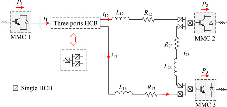
FIGURE 2. Typical three-terminal VSC-HVDC system with M-HCBs.
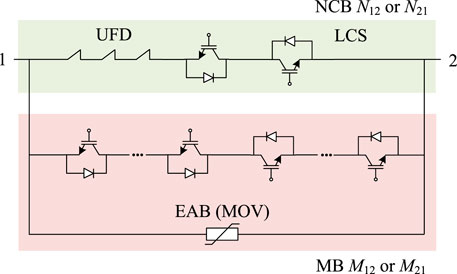
FIGURE 3. Structure of ABB’s hybrid DC circuit breakers.
2.1 Basic concepts of graph theory
The directed graph is a data structure composed of a vertex set V and an edge set E, and Graph = (V, E), abbreviated as G = (V, E). E = {<v, w>| v, w∈V, and Pvw}
Pvw defines the meaning of edge <v, w>. In this article, P represents the edge type and vw represents the edge direction (from v to w).
Then, if there are n vertexes in a directed graph, the adjacency matrix is established as
The detailed method for establishing the adjacency matrix will be described in subsection 2.3.
2.2 Graph representation of the M-HCB
The method to convert the M-HCB topology into the directed graph is defined as follows:
For vertex: In the three-port HCB, three port points must exist; in graph theory, it can be abstracted as VP (port vertex), VP = 3. The remaining common connection points can be abstracted as VC (common vertex). The vertexes are usually expressed by numbers in the directed graph, the port points are numbered 1, 2, and 3, and the common connection points are sorted after the port points.
For edge: The NCB can be denoted by Nvw in the graph; the MB and EAB can be considered as a whole, represented by Mvw, as illustrated in Figure 3. In addition, in many topologies, there will also be diode branches, denoted by Dvw.
Summarizing the aforementioned definitions, the abstract rules are defined, as shown in Table 1.
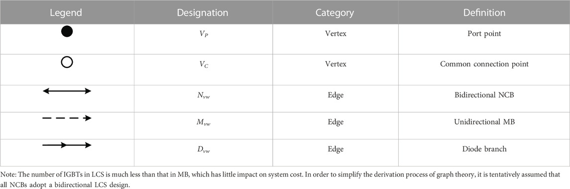
TABLE 1. Abstract rules of M-HCBs.
The previous M-HCB topologies can be abstracted into directed graphs and are divided into several categories according to the number of common connection points:
1) VC = zero: A unidirectional fault blocking solution proposed by Li et al. (2018) is abstracted into a directed graph, as shown in Figure 4A.
2) VC = one: The directed graph in Figure 4B is a bidirectional fault blocking topology, as proposed by Li et al. (2018).
3) VC = two: Three examples are explained here, as shown in Figure 4C–E. Although they belong to different design ideas, they are still regarded as the same type in graph theory.
4) VC = three: The situation is more complicated due to more common connection points. In Figure 4F, only one unidirectional MB, whose blocking capacity is the system voltage, is used to block the fault current.
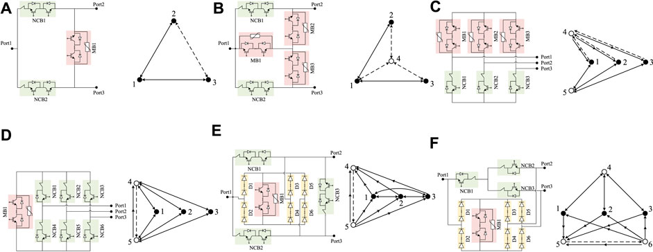
FIGURE 4. Previous three-port HCB topologies and their corresponding graphs: (A) topology proposed by Li et al. (2018), (B) topology proposed by Li et al. (2018), (C) topology proposed by Mokhberdoran et al. (2018), (D) topology proposed by Kontos et al. (2018), (E) topology proposed by He et al. (2020), and (F) topology proposed by Xiao et al. (2020).
2.3 Corresponding adjacency matrix
In graph theory, the adjacency matrix can denote the relationship of the graph clearly. On the other hand, it is difficult for computers to recognize image statements but easy for math matrices.
As explained previously, Graph = (V, E), and the labels of vertexes in the graph are 1, 2, …n. An n×n matrix C = [Cvw] is named the adjacency matrix and
where P represents the edge type from vertex v to vertex w, such as Nvw, Mvw, and Dvw.
The matrix elements do not consider the parallel multiple branch situation in the ABB scheme in Figure 3 because the core idea of the M-HCB is to share the main breaker branch.
However, like Nvw, Mvw, and Dvw, symbolic variables are hard to be identified in computers. It will present many difficulties in the subsequent M-HCB topology screening, such as the complex algorithm and inefficient operations in computers.
Inspired by the concept of resistance, this paper innovatively proposes the conception of a ‘roadblock’ to simplify adjacency matrices of M-HCB topologies. The purpose of setting the value with a difference of 100 times among three kinds of branches is to facilitate distinction and operation, as shown in Table 2.
TABLE 2. ‘Roadblock’ in M-HCB Topology.
The number of various types of branches on the path can be easily derived by ‘roadblock,’ and it will have a huge impact on proposing electrical rules in subsection 3.3. Moreover, the concept of ‘roadblock’ also fits the definition of the directed weighted adjacency matrix (Eq. 2) in graph theory.
The adjacency matrices C are directly framed, as derived from abstract graphs. The following are the adjacency matrices corresponding to previous examples in Figure 4.
The aforementioned topologies are proposed at different times, so their performance and characteristics are also different. Four characteristics are summarized to evaluate M-HCB topologies, as shown in Table 3. They are applicable to different application scenarios, according to the different costs and functional requirements. These characteristics can also be analyzed through the adjacency matrix, as mentioned in Section 3. Therefore, the topology type is quickly deduced according to the actual application requirements through the programmable mathematical algorithm rather than spending years (2018–2022) relying on the experience of researchers. In addition, other characteristics can be proposed according to the requirements.
TABLE 3. Characteristics and comparison of previous topologies.
Non-fault line recovery: When the fault current is cleared, the non-fault lines can be restored to normal operation.
Backup blocking (Zhu et al., 2023): When the fault current is transferred to the MB, the line with short-circuit fault needs to open the UFD(s) to physically isolate the fault point. The backup blocking capacity represents that if corresponding UFD(s) have been broken, other UFD(s) could be used to isolate the fault point.
3 Topology searching algorithm
The flow diagram of the topology searching algorithm proposed in this paper is shown in Figure 5. It is divided into three parts: the construction of graphs, the search for feasible paths, and the filtering of electrical rules.
1) The construction of graphs: The number of port points, the number of common connection points, and the type of edge are input; then, the algorithm constructs M-directed graphs for all situations and generates the adjacency matrix of each graph.
2) The search for feasible paths: According to the established adjacency matrix of each graph, the algorithm searches the feasible paths between every two port points of each graph and then filters feasible paths of each adjacency matrix preliminarily.
3) The filtering of electrical rules: Here, three kinds of rules are proposed: preliminary rules, Rules, and Sub-rules. Then, the algorithm filters the feasible paths between every two port points of each graph and outputs the graphs, which satisfy the selected electrical rules.
FIGURE 5. Topology searching algorithm flow diagram.
3.1 The construction of graphs
In this paper, the M-HCB topologies take three ports as examples, so the number of port points is three.
In the previous section, the number of common connection points could take values of zero, one, two, and three. The cases are not considered where the number of common connection points is zero or three due to very little or much traversal numbers; the detailed reason and specific traversal number of the connection points will be described in Figure 6. In addition, very few topologies use three common connection points.
FIGURE 6. Generation algorithm principle diagram (A) one common connection point situation (B) two common connection points situation
The algorithm is backward compatible, which means that one common connection point situation includes the zero common connection point situation without restrictions. However, different rules are flexibly applied to different common connection point situations in the following section.
Similarly, in the previous section, the type of edge could be divided into three categories: the bidirectional NCB, unidirectional MB, and unidirectional diode branch.
In order to reduce the complexity of the algorithm, the category ‘unidirectional MB’ is simplified to ‘bidirectional MB’. Although the cost difference between the unidirectional MB and bidirectional MB is significant, the M-HCB topology using the unidirectional MB can meet the requirements of the circuit breaker better when changing to the bidirectional MB.
So there are five connection methods between every two points: the bidirectional NCB, bidirectional MB, diode branch (go), diode branch (back), and not being connected. If the algorithm is not simplified for the MB, connection methods will increase by two types: the unidirectional MB (go) and unidirectional MB (back). It is noted that there are only connection methods between every two points, and the total number of directed graphs is will exponentially grow.
For the one common connection point, the specific traversal number is 33×53 = 3,375, as shown in Figure 6A. The number of connection methods between every two port points is three because the branch between port points must be controllable, and the diode branch is an uncontrollable branch.
There are 33×57 = 2109375 adjacency matrices for two common connection points, as shown in Figure 6B. The detailed reason for abandoning the situation for three common connection points is as follows: using the generation algorithm proposed in this section, it is observed to be 55 × 2109375 adjacency matrices. An adjacency matrix example of Output 913 in Figure 9A is illustrated in Figure 7.
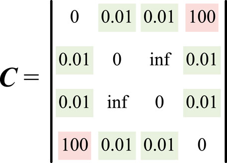
FIGURE 7. Adjacency matrix example.
3.2 The search for feasible paths
The algorithm previously obtained 3,375 adjacency matrices and 2109375 adjacency matrices separately; many isomorphic graphs are hidden in them.
Reducing isomorphic graphs is a problem in graph theory; first, the rules of the generation algorithm are used to reduce part of isomorphic graphs and their corresponding adjacency matrices. The number of adjacency matrices is, respectively, reduced to 1,250 and 781,250 through this operation. The reduction efficiency is 63%.
The depth-first find-path algorithm is used to directly obtain all feasible paths between every two port points and their corresponding roadblocks in each adjacency matrix. The pseudocode for the find-path algorithm is illustrated in Algorithm 1.
Algorithm 1. Depth-first find-path
Input: adjacency matrix, initial port point, terminate port point
Output: feasible paths and their roadblocks
1 Initialize path length, last point, next possible points (At the beginning, path length = 1, last point = initial port point)
2 If last point = terminate port point
3 return feasible paths and roadblocks
4 For each next possible point
5 If next possible point = terminate port point
6 Form feasible path and roadblock, remove it
7 If next possible point is in the part path
8 Remove this next possible point
9 For remaining next possible points
10 Put the next possible point in the part path
11 Place the part path as initial port point and algorithmic recursion
12 Connect all feasible paths and roadblocks
13 Return feasible paths and their roadblocks
The find-path algorithm runs six times for six port point combinations including 1 to 2, 2 to 1, 1 to 3, 3 to 1, 2 to 3, and 3 to 2 to obtain six sets of feasible paths and roadblocks.
Then, to filter feasible paths preliminarily after using the find-path algorithm, the adjacency matrices whose number of feasible paths is less than two between any two port points are removed because feasible paths between two port points include at least one MB and one NCB in M-HCB topologies.
After running the algorithm through this part, the algorithm obtains feasible paths and roadblocks in each adjacency matrix, and it also removes some unfeasible adjacency matrices. Now, the number of adjacency matrices is, respectively, reduced to 576 and 480,168. The feasible paths between 1 and 2 of Output 913 in Figure 9A are taken as examples to illustrate the principle, as shown in Table 4.

TABLE 4. Feasible path examples.
3.3 Electrical rules
In the algorithm, electrical rules are divided into three categories. They are preliminary rules, Rules, and Sub-rules in the order of the algorithm, as illustrated in Figure 10. However, this section will introduce them according to their importance.
After obtaining the feasible paths, it is necessary to determine whether the feasible paths satisfy the electrical rules as an M-HCB or some characteristic requirements. The ‘feasible path’ is simplified as ‘path’ in this part.
For the adaptability and high performance of the output topologies, unidirectional blocking schemes are not considered in this article, and the generated topologies are all bidirectional blocking by default.
The MB and NCB are two important features of the M-HCB. The topology has three basic functions as an M-HCB:
1) Normal working function: When no fault occurs, the normal current is conducted through NCB(s) completely to reduce losses.
2) Blocking fault current function: When a short-circuit fault occurs, the fault current can be transferred to the MB(s) for UFD(s) in NCB(s) opening without the arc.
3) Blocking normal load current function: During normal operation, it has the ability to interrupt the normal load current by MB(s).
According to the aforementioned three basic functions, three basic rules are proposed.
Rule 1. There should be at least one path entirely composed of NCB(s) between every two port points to ensure the normal current is flowing. ‘Entirely’ means that the path should not include the MB or diode branch due to their high on-state loss.Although it is difficult for the algorithm to calculate the number of symbolic variables, due to the introduction of the roadblock concept, the algorithm could easily judge whether the path satisfies Rule 1. For six sets of paths and roadblocks in each adjacency matrix, the condition of satisfying Rule 1 is that there is at least one path in each set with a roadblock greater than 0 and less than 0.03. This restriction allows only one or two NCB(s) in the path, and the reason for no more NCBs is to reduce on-state loss.
Rule 2. There should be at least one path that contains MB(s) between every two port points, and the paths are used to block the fault current when the short-circuit fault occurs.Judgment of existence seems easier than Rule 1; at least one path in each set with a roadblock greater than 100 can satisfy Rule 2. However, when the path contains another port point, the position of MB may result in fault current blocking failure. The solution given is that the path could pass another port point, but there should be at least 1 MB between the port point being passed and the short-circuit point. The pseudocode for MB judgment in the fault current algorithm is illustrated in Algorithm 2.
Algorithm 2. MB judgment in the fault current
Input: adjacency matrix, paths, and roadblocks
Output: 0 or 1 (1 represents a valid MB path)
1 If roadblock < 100
2 return 0
3 Initialize another port point in path
4 If another port point = empty
5 return 1
6 else Initialize terminate port point in path; luzu1 = 0
7 For another port point: 1: terminate port point
8 Calculate the sum of luzu1
9 If luzu1 > 100
10 return 1
11 else return 0
Rule 3. This rule is for blocking the normal load current; theoretically, satisfying Rule 2 can block the fault current, and it can also easily block the normal load current. However, the direction of the fault current and normal load current is different: In most cases for three-port HCBs, the direction of the fault current is converging to a port point, while the direction of the normal load current is radiating outward from a port point.So blocking the normal load current also has the problem of passing through another port point. It is the same problem as in Rule 2; the pseudocode for MB judgment in the load current is shown in Algorithm 3.
Algorithm 3. MB judgment in the load current
Input: adjacency matrix, paths, and roadblocks
Output: 0 or 1 (1 represents a valid MB path)
1 If roadblock < 100
2 return 0
3 Initialize another port point in the path
4 If another port point = empty
5 return 1
6 else Initialize initial port point in the path; luzu2 = 0
7 For initial port point: 1: another port point
8 Calculate the sum of luzu2
9 If luzu2 > 100
10 return 1
11 else return 0
The aforementioned three rules are the main rules that must be satisfied by each output graph and its corresponding adjacency matrix from the algorithm. Moreover, some preliminary filtering rules in the front and Sub-rules for Table 3 in the back could be added according to the demand.
Preliminary rules: 1) restrict the number of MBs, 2) restrict the number of NCBs, 3) remove the adjacency matrices with the existence of one degree point, and 4) remove the adjacency matrices with a pure diode branch between any two port points.
Preliminary rules 1) and 2) are simply derived by calculating the number of ‘100’ and ‘0.01’ in the adjacency matrix. Preliminary rule 3) is judged by calculating the degree of every point, and preliminary rule 4) needs to determine whether there is a path consisting of only diode branches in each set before judging Rules by roadblock rounding and calculating the remainder.
Sub-rules are the same as Rules, and they are still judged for six sets of paths and roadblocks in each adjacency matrix. Significantly, the graphs must satisfy Rules before making Sub-rule judgments; the output adjacency matrices from Rules are all bidirectional blocking; only two optional characteristics are explained in Table 3, and their corresponding Sub-rules are formulated in order.
Sub-rule 1 (non-fault line recovery): If there is a path that satisfies Rule 1 and does not pass through another port point between every two port points, the graph has non-fault line recovery ability.
Only the ideas of the first five lines of Algorithm 2 need to be used for judging Sub-rule 1. The algorithm initializes ‘another port point’ in the path, which satisfies Rule 1 and then determines whether ‘another port point’ is empty.
Sub-rule 2 (backup blocking): If there is a path that satisfies Rule 1 containing two or more NCBs between every two port points, the graph has the backup blocking ability.
To judge Sub-rule 2, we calculated the number of NCBs in the path, which satisfies Rule 1 by roadblock rounding and calculating the remainder.
After the filtering of Rule 1, Rule 2, and Rule 3, the search results should have the functions of bidirectional M-HCBs. As for the preliminary rules, Sub-rule 1 and Sub-rule 2, they are optional rules of the algorithm to satisfy the actual application requirements. If other characteristics are required in the future, extra corresponding Sub-rules will be added in the algorithm.
4 Novel M-HCB topologies
The overall topology searching algorithm, shown in Figure 5, was implemented using MATLAB and ran on AMD Ryzen 5800H CPU with 16GB RAM.
4.1 One common connection point
There are only 1,250 graphs, and their corresponding adjacency matrices need to be filtered for one common connection point situation. So, an appropriate reduction in rules could get more results that are worth analyzing. The rules used at this time are shown in Figure 8.
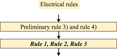
FIGURE 8. Electrical rules for one common connection point.
In the previously introduced computer configuration, running the topology searching algorithm takes approximately 1 s in this situation. The algorithm outputs 40 graphs and their adjacency matrices, and most of them are isomorphic due to the isomorphism problem; some outputs have no advantages over the proposed topologies. Here, some output topologies selected are shown in Figure 9.
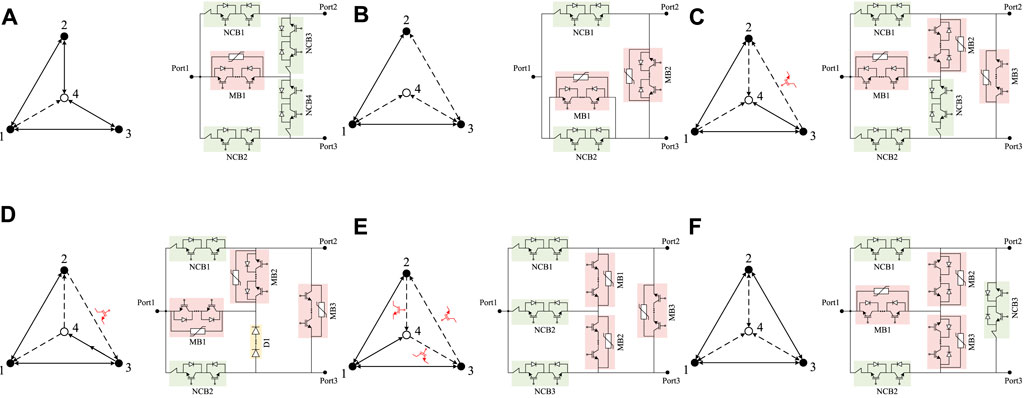
FIGURE 9. Three-port HCB topologies searched by the algorithm in the one common connection point situation: (A)Output 913, (B) Output 1,027, (C) Output 1,033, (D) Output 1,034, (E) Output 1,057, and (F) Output 1,157.
MBs that must be packaged without anti-parallel diodes are indicated in the figures; other MBs are packaged with anti-parallel diodes by default.
Output 907 in Figure 4B is the topology proposed by Li et al. (2018), and it does not have the ‘non-fault line recovery’ ability when the fault occurs on port 1.
Output 913 in Figure 9A is the optimal performance topology in the one common connection point situation. It has the ‘non-fault line recovery’ ability for all port points after analysis, and only one bidirectional MB is required.
Output 1,027 in Figure 9B is an improvement of Figure 4A, which can be simplified to a zero common connection point situation. It realizes bidirectional blocking by adding another bidirectional MB parallel to the existing NCB.
Outputs 1,033, 1,034, and 1,057 all require three unidirectional MBs to meet the selected electrical rules. They all use one or more MB(s) without anti-parallel diodes. Output 1,034 is the best cost among the three.
Output 1,157 in Figure 9F is an improvement of Output 907, and it has the ‘non-fault line recovery’ ability in all ports by adding one NCB. For the star structure of MBs in Output 907 and 1,157, three bidirectional MBs are equivalent to three unidirectional MBs, and the MOVs in bidirectional MB arrangement only need to withstand half the system voltage.
Through the aforementioned analysis, the algorithm can search for new topologies while verifying existing topologies and possibly find improvements to existing topologies. There is no limit on the NCB and MB number for the diversity of the output. The output topologies are all bidirectional blocking in terms of characteristics, and the comparison of them is shown in Table 5.
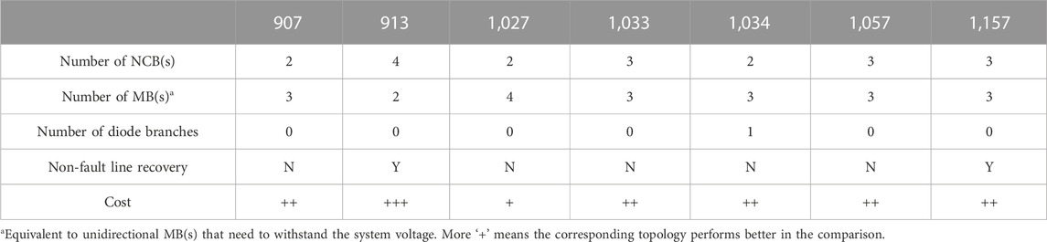
TABLE 5. Comparison in the one common connection point situation.
4.2 Two common connection points
Unlike the one common connection point situation, there are 781,250 graphs, and their corresponding adjacency matrices need to be filtered for two common connection point situations. All electrical rules are used from the previous section, as illustrated in Figure 10. Running the overall topology searching algorithm takes approximately 5.5 min. The algorithm outputs 195 graphs and their adjacency matrices; only some output topologies are displayed due to the same isomorphism problem.
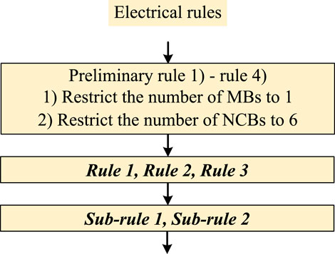
FIGURE 10. Electrical rules for two common connection points.
Output 23,436, shown in Figure 11A, which uses a small number of branches, is a simple way to configure various branches. The MB located in 1–4 can be configured to replace any of the other five NCBs. Output 39,062 is the topology proposed by Kontos et al. (2018), as illustrated in Figure 4C and Table 3.
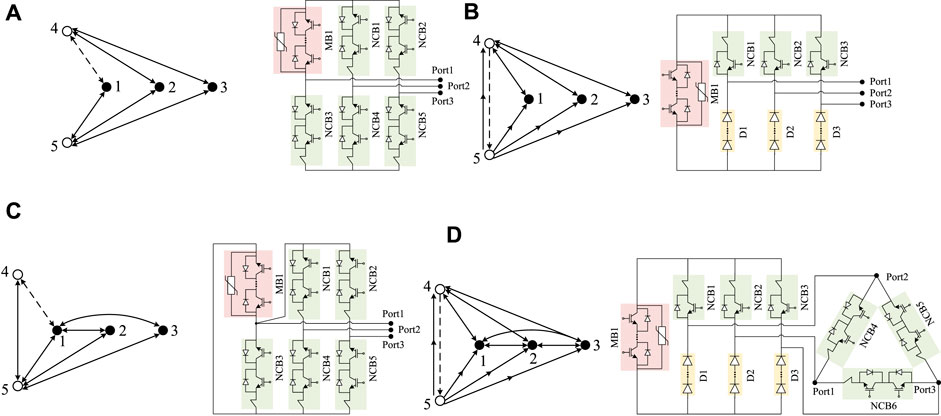
FIGURE 11. Three-port HCB topologies searched by the algorithm in two common connection point situations: (A)Output 23,436, (B) Output 39,372, (C) Output 562,813, and (D) Output 742,497.
Output 39,372 in Figure 11B is the optimal performance topology in this situation. It reduces the cost by replacing three NCBs with three diode branches compared to Output 39,062.
Output 562,813 in Figure 11C is an improvement of Output 913 in the previous part. It obtains the ‘backup blocking’ ability by adding additional NCBs.
Output 742,497 in Figure 11D also shows good performance. The additional triangular configuration of NCBs provides low-loss branches when flowing through the normal load current and provides more feasible paths for blocking fault current.
In two common connection point situation, the proportion of output reduction is large (781,250–195) due to strict filtering rules. If the algorithm reduces the electrical rules appropriately, such as abandoning Sub-rule 2 or reducing the limit on the NCB and MB number, it may not only output more topologies but also increase the workload of filtering results. The output topologies are all bidirectional blocking, and they have ‘non-fault line recovery’ and ‘backup blocking’ abilities in terms of characteristics. The comparison of them is shown in Table 6.
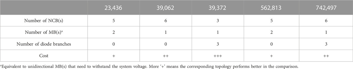
TABLE 6. Comparison in two common connection points situation.
5 Conclusion
A novel M-HCB topology searching algorithm based on graph theory is proposed in this paper. The algorithm uses ‘roadblock’ to simplify adjacency matrices in the mathematization of the topologies and then enumerates all matrices and filters them by electrical rules. Some new M-HCB topologies are obtained from the three-port example-specific application. This proves that the new method can search M-HCB topologies effectively. It greatly reduces the innovation time of the new M-HCB topology, which can be customized according to the actual requirements. The idea of the topology searching algorithm and the concept of ‘roadblock’ can be applied to find other types of circuit breaker topologies or even power supply topologies.
Data availability statement
The original contributions presented in the study are included in the article/Supplementary Material; further inquiries can be directed to the corresponding author.
Author contributions
SH: writing—original draft and algorithm implementation. JZ: idea and writing—original draft. QZ: drawing figures and editing. XG: drawing figures and editing. JY: process analysis and supervision. TW: supervision.
Funding
This work was supported in part by the National Natural Science Foundation of China under Grant 51607171 and the Institute of Electrical Engineering, CAS, under grants E155610301 and E155610201.
Acknowledgments
This is a brief acknowledgment of the contributions of individual colleagues, institutions, or agencies that assisted the writers’ efforts in the writing of this paper.
Conflict of interest
The authors declare that the research was conducted in the absence of any commercial or financial relationships that could be construed as a potential conflict of interest.
Publisher’s note
All claims expressed in this article are solely those of the authors and do not necessarily represent those of their affiliated organizations, or those of the publisher, the editors, and the reviewers. Any product that may be evaluated in this article, or claim that may be made by its manufacturer, is not guaranteed or endorsed by the publisher.
References
Chen, G., Jin, Z., Liu, Y., Hu, Y., Zhang, J., and Qing, X. (2019). Programmable topology derivation and analysis of integrated three-port dc–dc converters with reduced switches for low-cost applications. IEEE Trans. Ind. Electron. 66 (9), 1–6660. doi:10.1109/TIE.2018.2877159
Debnath, S., Qin, J., Bahrani, B., Saeedifard, M., and Barbosa, P. (2015). Operation, control, and applications of the modular multilevel converter: A review. IEEE Trans. Power Electron. 30 (1), 37–53. doi:10.1109/TPEL.2014.2309937
Guo, X., Zhu, J., Yin, J., Wang, W., and Wei, T. (2022). Topology optimization and evaluation of multiport hybrid dc circuit breaker based on graph theory. Energy Rep. 8, 1002–1012. doi:10.1016/j.egyr.2021.12.004
Guo, Y., Li, H., Gu, G., Zeng, D., and Wang, G. (2021). A multiport dc circuit breaker for high-voltage dc grids. IEEE J. Emerg. Sel. Top. Power Electron. 9 (3), 3216–3228. doi:10.1109/JESTPE.2020.3018646
He, J., Luo, Y., Li, M., Zhang, Y., Xu, Y., Zhang, Q., et al. (2020). A high-performance and economical multiport hybrid direct current circuit breaker. IEEE Trans. Ind. Electron. 67 (10), 8921–8930. doi:10.1109/TIE.2019.2947835
Kontos, E., Schultz, T., Mackay, L., Ramirez-Elizondo, L., Franck, C., and Bauer, P. (2018). Multi-line breaker for hvdc applications. IEEE Trans. Power Del 33 (3), 1469–1478. doi:10.1109/TPWRD.2017.275464933
Li, C., Liang, J., and Wang, S. (2018). Interlink hybrid dc circuit breaker. IEEE Trans. Ind. Electron. 65 (11), 8677–8686. doi:10.1109/TIE.2018.2803778
Li, H., Wang, W., Li, Y., Zeng, Y., Su, W., and Zhang, B. (2019). Programmable topology searching algorithm for S1D1L2C1 type DC-DC converters based on graph theory. Proc. CSEE 41 (16), 5670–5683. doi:10.13334/j.0258-8013.pcsee.201750
Li, K., Hu, Y., and Ioinovici, A. (2017b). Generation of the large dc gain step-up non-isolated converters in conjunction with renewable energy sources starting from a proposed geometric structure. IEEE Trans. Power Electron. 32 (7), 5323–5340. doi:10.1109/TPEL.2016.260950132
Li, Z., Tang, Y., Zhao, Z., Wu, X., Han, Y., Li, L., et al. (2017a). The model and parameters based on the operation mode of a 500kV multi-terminal flexible DC power grid. Int. J. Power Eng. Eng. Thermophys. 1, 16–24. doi:10.23977/poweet.2017.11003
Liu, G., Xu, F., Xu, Z., Zhang, Z., and Tang, G. (2017). Assembly hvdc breaker for hvdc grids with modular multilevel converters. IEEE Trans. Power Electron. 32 (2), 931–941. doi:10.1109/TPEL.2016.2540808
Liu, K., and Lee, F. (April, 1988). Topological constraints on basic PWM converters. IEEE Power Electronics Specialists Conference, Kyoto, Japan, 164–172. doi:10.1109/PESC.1988.18130
Meah, K., and Ula, S. (2007). Comparative evaluation of HVDC and HVAC transmission systems. IEEE Power Eng. Soc. Gen. Meet., 1–5. doi:10.1109/PES.2007.385993
Mokhberdoran, A., Van Hertem, D., Silva, N., Leite, H., and Carvalho, A. (2018). Multi-port hybrid hvdc circuit breaker. IEEE Trans. Ind. Electron. 65 (1), 309–320. doi:10.1109/TIE.2017.2719608
Ogata, M., and Nishi, T. (2005). Graph-theoretic approach to the design of four-switch DC-DC converters. IEEE Int. Symp. Circuits Syst., 768–771. doi:10.1109/ISCAS.2005.1464701
Ogata, M., and Nishi, T. (May, 2003). Topological criteria for switched mode DC-DC converters. IEEE International Symposium on Circuits and Systems. (ISCAS), Bangkok, Thailand, 184–187. doi:10.1109/ISCAS.2003.1204986
Oubelaid, A., Taib, N., Rekioua, T., Bajaj, M., Blazek, V., Prokop, L., et al. (2022d). Multi source electric vehicles: Smooth transition algorithm for transient ripple minimization. Sustainability 22 (18), 6772. doi:10.3390/s22186772
Oubelaid, A., Albalawi, F., Rekioua, T., Ghoneim, S., Taib, N., and Abdelwahab, S. (2022a). Intelligent torque allocation based coordinated switching strategy for comfort enhancement of hybrid electric vehicles. IEEE Access 10, 58097–58115. doi:10.1109/ACCESS.2022.3178956
Oubelaid, A., Alharbi, H., Humayd, A., Taib, N., Rekioua, T., and Ghoneim, S. (2022c). Fuzzy-energy-management-based intelligent direct torque control for a battery-supercapacitor electric vehicle. Sustainability 14 (14), 8407. doi:10.3390/su14148407
Oubelaid, A., Taib, N., Nikolovski, S., Alharbi, T., Rekioua, T., Flah, A., et al. (2022b). Intelligent speed control and performance investigation of a vector controlled electric vehicle considering driving cycles. Electronics 11 (13), 1925. doi:10.3390/electronics11131925
Qu, L., Yu, Z., Chen, Z., Zhang, X., Chen, J., Liu, Y., et al. (2019). Engineering application of three-terminal hybrid dc circuit breaker. Automation Electr. Power Syst. 43 (23), 141–146+154. doi:10.7500/AEPS20190509005
Ranjana, M., Mule, S., Arjun, H., and Kulkarni, R. (March, 2016). DC-DC buck converter through duality approach for current based loads. IEEE International Conference on Electrical, Electronics, and Optimization Techniques (ICEEOT), Chennai, India, 2622–2625. doi:10.1109/ICCPCT.2016.7530111
Tang, G., He, Z., Pang, H., Huang, X., and Zhang, X. (2015). Basic topology and key devices of the five-terminal dc grid. CSEE J. Power Energy Syst. 1 (2), 22–35. doi:10.17775/CSEEJPES.2015.00016
Wang, S., Ming, W., Ugalde-Loo, C. E., and Liang, J. (2022). A low-loss integrated circuit breaker for hvdc applications. IEEE Trans. Power Del 37 (1), 472–485. doi:10.1109/TPWRD.2021.3063515
Wang, S., Ugalde-Loo, C. E., Li, C., Liang, J., and Adeuyi, O. D. (2020). Bridge-type integrated hybrid dc circuit breakers. IEEE J. Emerg. Sel. Top. Power Electron. 8 (2), 1134–1151. doi:10.1109/JESTPE.2019.29004928
Wen, W., Li, B., Li, B., Liu, H., He, J., Ma, J., et al. (2019). Analysis and experiment of a micro-loss multi-port hybrid dccb for mvdc distribution system. IEEE Trans. Power Electron 34 (8), 7933–7941. doi:10.1109/TPEL.2018.2881000
Xiao, H., Xu, Z., Xiao, L., Gan, C., and Dai, L. (2020). Components sharing based integrated hvdc circuit breaker for meshed hvdc grids. IEEE Trans. Power Del. 35 (4), 1856–1866. doi:10.1109/TPWRD.2019.295572635
Zhang, S., Zou, G., Wei, X., and Sun, C. (2021). Diode-bridge multiport hybrid dc circuit breaker for multiterminal dc grids. IEEE Trans. Ind. Electron. 68 (1), 270–281. doi:10.1109/TIE.2020.2965459
Keywords: hybrid DC circuit breaker, graph theory, topology searching algorithm, HVDC, circuit fault
Citation: He S, Zhu J, Zeng Q, Guo X, Yin J and Wei T (2023) Topology searching algorithm for multi-port hybrid circuit breakers based on graph theory. Front. Energy Res. 11:1171815. doi: 10.3389/fenrg.2023.1171815
Received: 22 February 2023; Accepted: 15 March 2023;
Published: 03 April 2023.
Edited by:
Srete Nikolovski, Josip Juraj Strossmayer University of Osijek, CroatiaReviewed by:
Pradeep Vishnuram, SRM Institute of Science and Technology, IndiaAdel Oubelaid, Université de Bejaia, Algeria
Copyright © 2023 He, Zhu, Zeng, Guo, Yin and Wei. This is an open-access article distributed under the terms of the Creative Commons Attribution License (CC BY). The use, distribution or reproduction in other forums is permitted, provided the original author(s) and the copyright owner(s) are credited and that the original publication in this journal is cited, in accordance with accepted academic practice. No use, distribution or reproduction is permitted which does not comply with these terms.
*Correspondence: Jin Zhu, emh1amluQG1haWwuaWVlLmFjLmNu