 Shijun Shen
 Jiaoyuan Chen
 Chaofan Wang
 Chenyang Wang2
 Dawei Gong
- 1University of Electronic Science and Technology of China, Chengdu, China
- 2Key Laboratory of Thermal Power Technology, Wuhan Second Ship Design Institute, Wuhan, China
An underwater magnetic induction positioning and communication system and an energy-efficient distributed control algorithm for underwater base stations are proposed in this paper. The positioning and communication system consists of a number of base stations and an Autonomous Underwater Vehicle (AUV) equipped with three-axis source coils respectively. The AUV receives this signal and based on its amplitude and phase information is able to locate the AUV and communicate with the base station. Due to the short positioning distance of magnetic induction positioning technology, a large number of base stations need to be installed underwater, which puts high demands on the control of the base stations. In this paper, an energy-efficient distributed control algorithm for underwater base stations is proposed to enable the AUV to meet the operational requirements while minimizing the total energy consumption of the base station. According to the simulation results, the design solves the problem that traditional underwater positioning and communication equipment cannot work stably for long periods of time in a high radiated environment, with a positioning error of no more than 10 cm within a preset operating range, and the algorithm proposed in this paper is able to reduce energy wastage by about 20%.
1 Introduction
With the increasing scarcity of traditional energy sources, nuclear energy, as a new type of energy source with high energy density, has been greatly developed in recent years (Hisham and Carmine, 2016). Spent fuel generated during the power generation process is stored in pools, and leaks from spent fuel pools can cause very serious accidents if they are not detected and stopped in time (Hirano et al., 2012; Gu, 2018). Due to the high temperature, high humidity and radiation environment of nuclear pools, traditional manual inspections can have a significant impact on the health of workers. Using robots for nuclear pool operations can free workers from harsh environments (Bakari et al., 2007). Autonomous Underwater Vehicles (AUVs) are also exposed to high temperatures, humidity and radiation environment when inspecting and placing nuclear batteries, which places high demands on communication and positioning components.
In terms of communications, the complex environment underwater causes electromagnetic waves to be severely attenuated as the frequency rises (Zhang et al., 2011; Domingo, 2012). As a result, electromagnetic wave communication technologies that can be used in underwater environments often require large size coils to provide low frequency electromagnetic waves. For example, EM wave communication systems on submarines typically require towed antennas that are hundreds of meters long, which is not clearly suitable for limited water applications.
Compared to the strong attenuation of electromagnetic waves, sound waves are less attenuated in water and can travel over distances of several tens of kilometers. However, due to its narrow bandwidth, large propagation delay and the multipath effects it produces in confined spaces (Liu et al., 2012). This makes acoustic communications also have many limitations in practical applications.
The channel of MI communication is less influenced by the medium and is more stable (Akyildiz et al., 2015). In addition, MI communication has the advantage of a small coil size. It has been widely used in areas such as wireless earth-permeable communication (Sun and Akyildiz, 2010; Lin et al., 2015). The most important thing is that MI coils are made of ordinary copper wire and are not affected by nuclear radiation.
In terms of positioning, the MI positioning system works by constructing a magnetic dipole model. The three coils of the source coil are orthogonal and are excited in turn by an AC signal of the same frequency. The amplitude and phase information of the signals is obtained using the receiving coils, which can then be algorithmically obtained (Hu et al., 2012).
In terms of base station control, traditional magnetic induction positioning application scenarios are often small and do not need to consider base station control methods (Hu et al., 2005), but in nuclear pools, due to the huge area, multiple base stations need to be laid for cooperative positioning, opening them all will waste a lot of energy, so the control of base stations not only need to consider the conditions of the AUV, but also need to reduce energy consumption as much as possible.
A wireless robotic capsule endoscope for digestive tract examination using magnetic induction positioning was displayed in (Hu et al., 2005). A small permanent magnet was added to the capsule to create a permanent magnetic field in the patient and the capsule position is then determined by an external sensor. C. Hu, Z et al. proposed a two-dimensional magnetic induction positioning system for a domestic robot with base station coils mounted on the ceiling, and because the height was fixed in this scenario, only one set of coils had to be used for the base station (Hu et al., 2015). T. Li and L. Chen investigated evolutionary clustering to improve the quality of clusters for moving objects (Li et al., 2022).H. G. Zhang et al. proposed distributed algorithms to obtain the most available solution for the energy management system through local communication and computation (Zhang et al., 2017). S.S. Ge et al. proposed a magnetic induction positioning application for the positioning of ships towing anchors, which solves the problem of short magnetic induction positioning distances by means of a recursive algorithm (Ge et al., 2014). T. Li and L. Chen optimize uncertain trajectories in the road network (Li et al., 2020; Li et al., 2021). H. Xu et al. designed an underwater MI communication system based on Quasi-cyclic LDPC codes (Xu et al., 2023). G. C et al. presented a wireless communication system based on magnetic coils for underwater vehicles and verified its performance in different water conditions (Canales-Gomez et al., 2022). Malik et al. conducted a study for underground magnetic induction communication, comparing both EM and MI methods and verifying the superiority of MI communication in some scenarios (Malik et al., 2022).
This paper consists of five parts, the first part is the introduction, the second part will introduce the framework and theoretical basis of the magnetic induction positioning and communication system, the third part will describe the energy efficient distributed control algorithm for underwater base stations. The fourth part will verify the performance of the system through simulation, and the fifth part is the conclusion.
2 Design of underwater magnetic induction positioning and communication system
2.1 Working environment
The pool of a nuclear power plant is a typical water structure with limited space. Its dimensions are usually rectangular pools of about 10–30 m each in length, width and depth. The bottom of the pool is fitted with storage tanks for nuclear fuel. As a result, the water in the pools has a high level of nuclear radiation. The temperature of the pools is generally in the range of 40°C–80°C due to the large amount of heat released during the decay of the nuclear fuel.
Hence, the communication and positioning system needs to be designed with the two characteristics of radiation resistance and high temperature resistance. For high temperature conditions, although the resistivity of copper wire varies with temperature, the pattern of its variation is known and therefore the calculated parameters can be adjusted by measuring the ambient temperature, thus avoiding the effects of temperature. For radiation environments, the positioning and communication system designed in this paper can all be made radiation-proof, with only the coils being exposed to radiation, and the coils are made of ordinary copper wire and are not affected by nuclear radiation. In summary, underwater MI communication is promising in this environment.
2.2 System topology
As shown in Figure 1, the system is composed of the transmitting part and receiving part. For transmitting part, this design uses Frequency-Shift Keying (FSK), where the data needs to be passed through a numerically controlled oscillator and digital-to-analogue converter to generate a high-frequency signal, which is enlarged by a power amplifier and passed to the source coil.
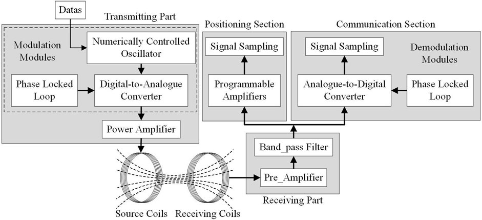
FIGURE 1. Circuit system composition.
For receiving part, the received voltage signal is first amplified and filtered through a band-pass filter to remove noise. After pre-processing the signal is split into two parts and passed into the position section and the communication section respectively. The positioning section samples the voltage after adjusting its magnitude with a programmable amplifier and then calculates the position of the AUV by means of a positioning algorithm.
2.3 Positioning method
The positioning system is composed of two sets of three-dimensional omnidirectional coils, with three mutually orthogonal magnetic induction coils of the source coil acting as signal sources, which in turn generate mutually orthogonal magnetic fields in space.
As shown in Figure 2, U, V, W represent the three source coils perpendicular to the x, y, z-axes; Bx, By, Bz represent the magnitude of the magnetic field induced by the three receiving coils; R represents the distance between the source coil and the induction coil.
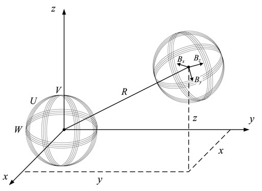
FIGURE 2. Underwater positioning model based on 3D omnidirectional magnetic induction.
A coil fed with current forms a magnetic dipole. Based on Magnetic dipole models for magnetic field distribution in three-dimensional space. The magnetic induction intensity generated by the three sets of coils U, V, W at any point p is defined as
where
Since the orthogonal rotation matrix does not change the magnitude of the magnetic induction intensity, we have
Hence, by superimposing the magnetic field we have
Similarly, Bv and Bu of coil V and W. Therefore, combined magnetic field is defined as
Hence, the distance R is defined as
The process of solving for y and z is similar to that for x and will not be repeated in this paper. At this point, the position of the induction coil has been fully determined.
2.4 Communication model building and operating frequency selection
The MI communication carries data through a pair of transceiver coils, the data information is carried by a time varying magnetic field generated by a modulated sinusoidal current along the transmitter coil antenna, and the receiver coil gets the signal from this time varying field and demodulates it to obtain the information.
The MI transceiver system needed to be modeled to do a quantitative study. The transmitter part is fed by a source with an internal impedance
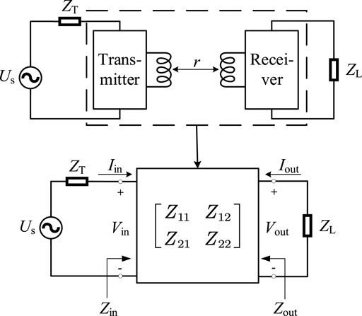
FIGURE 3. Two-port equivalent model for MI transceiver system.
The path loss of the MI transceiver system consists of two main components, one caused by eddy-current-loss caused by electrical conductivity in media and the other from the circuitry in the transceiver system.
For eddy-current-loss, water media tend to have a certain conductivity and coils working in water can produce eddy-current-effects which increase transmission losses dramatically. The attenuation is defined as
where μ is the magnetic permeability,
We notice from (8) that a lower operating frequency results in lower losses for defined environmental condition.
Therefore, the loss caused by eddy-current-loss in media can be defined as
Next, without considering the effect of media on the transceiver system and based on the two-port network model of the transceiver system, we can obtain the path loss by comparing the transmit power and the receive power.
Therefore, PL_ts is defined as
The transmitted and received powers are given by
During the operation of the MI transceiver system, the power at the transmitter side is not actually lost, but not fully absorbed by the receiver coil, so the influence of the receiver side should be ignored in the power calculation of the transmitter coil, the transmitted power of the MI system is redefined as follows:
Using (11)-(13) in (10), PL_ts is given as
We notice from (12) that the received power depends on the load impedance ZL, using the principle of impedance matching, the load receives the most power when
Next the impedance matrix of the two-port network needs to be calculated. As shown in Figure 4, we equate the MI transceiver system to an inductively coupled circuit, LTX and LRX represent the self-inductance of the transmitter and receiver antennas. RTX and RRX represent the coil resistance of the transmitter and receiver antennas. UM is caused by the time varying flux in the coil LTX through the mutual inductance M.
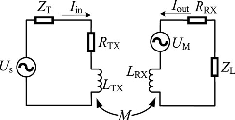
FIGURE 4. Equivalent circuit for coupled coils.
Hence, we can obtain the parameters of the impedance matrix by solving the model in Figure 4.
where
The self-inductance L of a coil is obtained as
where N is the number of turns of coil, l is the length of the solenoid and A is the cross-sectional area of the wire.
The mutual inductance M between two coils can be calculated as
where
Based on application scenario considerations, it is assumed that the transmitter and receiver coils are completely same, assuming
The coil resistance is given by
where ρ is the electrical resistivity.
Assuming there is no impedance in the transmitter circuit and using (15)-(20) in (14), PL_ts is defined as
Therefore, the path loss PL is defined as
The path loss as a function of the frequency and the transmission distance caused by eddy-current-effects and transceiver system are shown in Figure 5. The number of turns is 200, the radius of the transmitter and receiver is 0.2 m and the diameter of the wire is 0.3 mm.
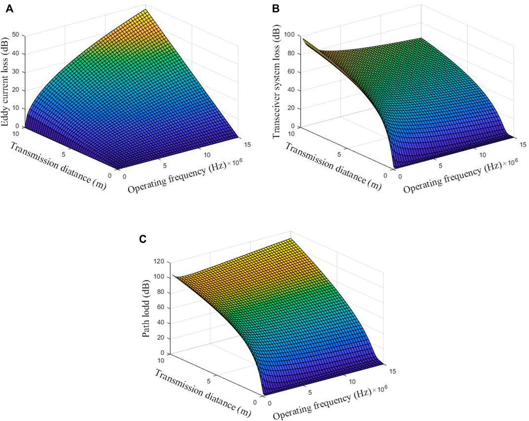
FIGURE 5. Path loss of the underwater MI communication channel. (A) Path loss caused by eddy-current-effects. (B) Path loss caused by transceiver system. (C) The total path loss.
We observe that the path loss caused by eddy-current-effects in Figure 5A is increased dramatically with the frequency and the transmission distance. The attenuation in formulas (8) is increased with the frequency and the eddy-current-loss defined in formulas (9) is increased with the transmission distance. Therefore, the higher the electrical conductivity of the system’s operating environment, the greater the effect of frequency on eddy current losses.
In Figure 5B, we observe that the path loss caused by transceiver system is increased with the transmission distance. Within 5 m, the path loss increases sharply, and the upward trend is slower out of 5 m. However, as the frequency increases, the path loss shows a decreasing trend at the same distance. Therefore, designing for higher frequencies will reduce the path loss of the system.
Hence, eddy-current-losses increase with frequency and transceiver-system-losses decreases with frequency, so we can obtain the optimum operating frequency based on the parameters of the coil and the data of the operating environment. Combining Figures 5A, B we can obtain the total losses of the system for this operating condition as shown in Figure 5C, where the optimum frequency is set to 2 MHz.
3 Energy efficient distributed control algorithm for underwater base stations
3.1 Control models
From the above derivation it is clear that
In traditional indoor multi-base station positioning applications, multiple base stations are often switched on to improve positioning accuracy, while in magnetic induction positioning and communication systems, the magnetic field decreases rapidly with distance, resulting in a large amount of energy wastage. As shown in Figure 6, this paper proposes a distributed control base station switching method, as well as three operating modes based on the different positioning accuracy requirements of underwater robots under different operating conditions, to ensure the normal operation of the robot and to significantly reduce energy wastage.
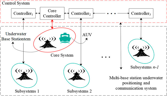
FIGURE 6. Distributed control of a magnetic induction positioning and communication system.
3.2 Analysis of base station operating modes and AUV operating modes
This paper divides the base station operating modes into two.
(1) Single base station operating mode
When low positioning accuracy is required, the base stations operate in this mode and only the nearest base station to the AUV is switched on at the same point in time for the whole system.
(2) Multi-base station operation mode
When the positioning accuracy is high, the base station operates in this mode, as shown in Figure 7. At point a, as it is closer to base station 1, base station 1 can meet its positioning and communication needs, so only base station 1 can be turned on at this location; at point b, as it is a certain distance away from both base station 1 and base station 2, so base station 1 and base station 2 are turned on to ensure the positioning accuracy and communication quality; at point c, as it is farther away from both base station 1 and base station 2, so base station 3 is turned on at the same time to further ensure its positioning accuracy and communication quality.
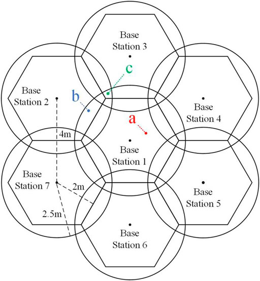
FIGURE 7. Multi-base Underwater base station distribution.
This paper sets out three operating modes for AUVs.
(1) Normal marching mode.
In this mode, the AUV requires low positioning accuracy and therefore uses a single base station operating mode. As shown in Figure 8A, In phase A, the AUV is closer to base station 2 and therefore turns on base station 2. In a similar way, phase B corresponds to base station 3, phase C to base station 1.
(2) Fixed-point working mode.
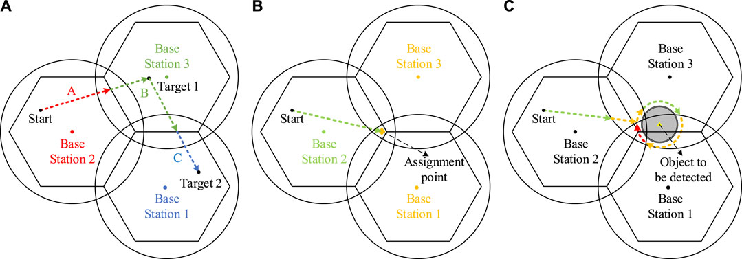
FIGURE 8. Working paths for different operating modes (A) Normal marching mode. (B) Fixed-point working mode.(C) Wrap-around detection mode.
As shown in Figure 8B, when the AUV needs to operate at a fixed-point, single base station operating mode may not be able to meet its required positioning accuracy. This mode uses Multi-base station operation mode once the AUV arrives at the operating point, improving its positioning accuracy and communication quality to meet the system’s requirements.
(3) Wrap-around detection mode.
In this mode, the AUV requires high positioning accuracy and therefore uses a multi-base station operating mode. The AUV starts from the starting point and stops when it reaches the detection radius of the object to be detected, then the AUV starts to lower to the set detection height and loop around the object. After completing the detection the AUV rises above the height of this object and proceeds to the next object to be detected. During this time the system is in multi-base station operating mode, to avoid any accidental position deviations that could cause the AUV to collide with the object. The path of the AUV run is shown in Figure 8C, green line indicates an open base station, yellow line means two and red line means three.
The basic working logic of AUV is as follows: After the AUV has been activated, it will first confirm its current position, receive the current job assignment and analyze the required base station operating modes. Next the AUV will perform a heading calculation based on the current position and the target position and proceed as calculated. During the course of the voyage the base station will be switched on and off in ways as described above. The AUV may deviate from the desired course due to uncertain underwater disturbances. The positioning system therefore operates continuously at regular intervals to calculate the latest position of the AUV and to correct the heading. After completing the expected work the AUV will wait underwater for a new work order to be given.
4 Simulation analysis
4.1 Settings
The experimental results of the underwater magnetic induction positioning and communication system will be presented in terms of positioning accuracy of the 3D coil and operating condition simulation. The various parameters of the coil are shown in Table 1.
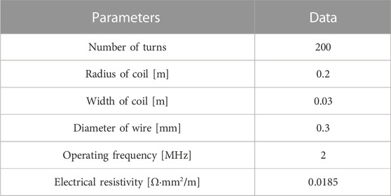
TABLE 1. Parameters of coils.
4.2 Normal marching mode simulation
In the normal marching mode, the starting point is (2, 2, 4) and the target point is (10, 6, 6), and the trajectories of AUVs in single base station operating mode and multi-base station operating mode are simulated respectively.
As shown in Figure 9A, when the AUV runs near the area where the working range of the two base stations meet, the positioning accuracy drops due to the opening of only one base station, and the trajectory of the AUV shows a more obvious deviation. Although the AUV can correct its own course to reach the target point, the course deviation makes the AUV’s running time longer. Its total elapsed time is 23.3 s, the same as the base station turn-up time.
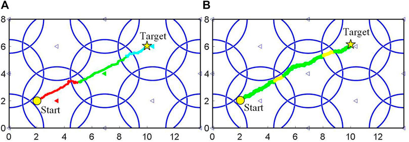
FIGURE 9. AUV’s trajectories in the normal marching mode [target point (10,6,6)]:(A) single base station operating mode;(B) multi-base station operating mode.
When using the multi-base station operating mode, as shown in Figure 9B, the AUV is still able to maintain a high level of positioning accuracy in the area where the working range of the two base stations meet, resulting in more accurate navigation of the AUV compared to the former and therefore a shorter running time in this mode. Its time was only 22.9 s. However, due to multiple base stations operating together over a period of time, the total turn-up time of its base stations reached 26.1 s. Total base station turn-up time improved by 2.8 s compared to single base station operating mode, in non-emergency situations, the multi-base station operation mode can waste a lot of energy.
When the AUV crosses the area where the working range of the three base stations meet, this wastefulness will be exacerbated. As shown in Figure 10, after changing the target position to (9, 7, 1), the AUV will cross several triple base stations crossover areas. In single base station operating mode, the total base station turn-on time is only 23.7 s, while in multi-base station operation mode it is 27.5 s.
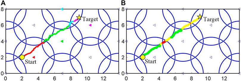
FIGURE 10. AUV’s trajectories in the normal marching mode [target point (9,7,1)]:(A) single base station operating mode;(B) multi-base station operating mode.
Simulations were carried out using the two base station operating modes by replacing different starting and target points. Experimental results showed that both allowed the robot to reach the target location, with an acceptable average increase in robot run time of 4.3% for the single base station mode compared to the multiple base station mode, and an average reduction in total base station turn-on time of 15.6%, with a maximum reduction of 24.2%. The algorithm keeps the increase in robot runtime within acceptable limits, while significantly reducing base station turn-up time and saving energy.
4.3 Fixed-point working mode simulaiton
As the point (2.3,4,2) is located at the junction of three base stations and the results are more representative, it is chosen as the operation point to verify the fixed-point operation mode in this paper.
As shown in Figure 11, When three base stations are on, the results are closer to the actual position of the AUV; when two base stations are on, the next closest, and the worst when a single base station is on.
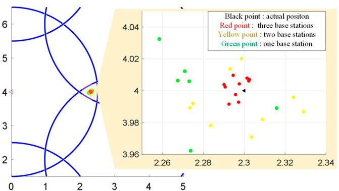
FIGURE 11. Continuous positioning results of AUV with different number of base stations (xy-projection plane).
In this paper, the squared heel of the deviation in the three directions is defined as the localization error
where (xa, ya, za) is the actual position of the AUV and (xc, yc, zc) is the calculated position of the AUV.
Therefor, the positioning deviation of AUV with different number of base stations is presented in Table 2. From Table 2, we can see that with the increase in the number of base stations, the positioning effect is significantly improved, and when three base stations are working simultaneously, the positioning error of the system can be controlled to within 5 cm.
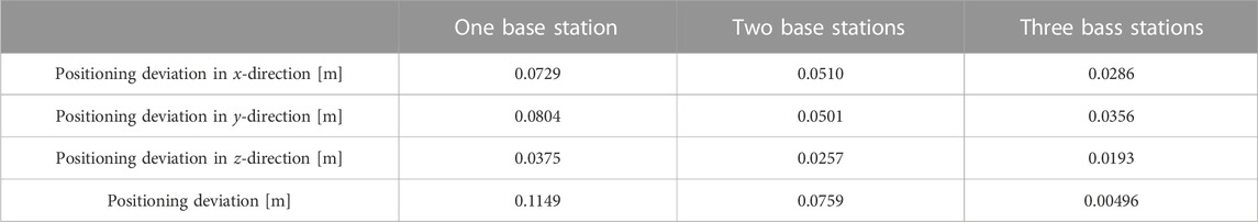
TABLE 2. Positioning deviation of AUV with different number of base stations.
4.4 Wrap-around detection mode simulation
In the wrap-around detection mode, the starting point is (1,1,4) and the coordinates of the objects to be detected are (2,2,1), (6,1,1), (12,2,1), (12,6,1), (6,4,1), (3,7,1); the radius of the objects to be detected are 3,4,1,2,5,3; the height of the objects to be detected are 0.3,0.2,0.2,0.1,0.5,0.4. (All units above are in meters).
The trajectory of the AUV is shown in Figure 12, the total time for the rise and fall of the AUV was 57 s, during which the base station was turned on in 78.9 s; the time for the AUV to move horizontally was 47.2 s, during which time the base station was turned on for 63.5 s; the time for AUV wrap-around detection was 36.7 s, during which time the base station was turned on for 45.8 s. The whole process took 140.9 s and 188.2 s for the base station turn-on. The wheel path planning algorithm enables the AUV to perform underwater surround detection tasks with a significant reduction in base station turn-up time and energy savings.
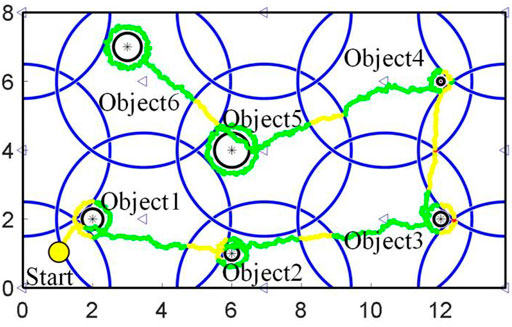
FIGURE 12. AUV’s trajectory in the wrap-around detection mode.
The simulation results prove that the proposed energy saving control algorithm for distributed underwater base station ensures that the AUV is able to perform its tasks under a variety of set conditions while saving energy wastage due to the opening of redundant base stations.
5 Conclusion
An underwater magnetic induction positioning and communication system and an energy-efficient distributed control algorithm for underwater base stations are proposed in this paper. The different requirements for positioning accuracy and communication quality under different operating conditions of AUVs are analyzed and two different base station control modes and a reasonable distributed control strategy for the three working states of AUVs. This system solves the problem of wireless positioning and communication in high radiation underwater environments, while the energy consumption of the base station is significantly reduced under the premise of ensuring the normal operation of the AUV, but the problem of how to improve the positioning and communication distance of this system is urgently needed by the serious attenuation of the magnetic field strength as the distance becomes larger. Experimental results show that with this control algorithm, the AUV can perform its tasks under three pre-defined operating conditions; in addition, the algorithm can reduce the energy loss by about 20% when moving over a large area and passing through more base station nodes. Compared to previous control algorithms, this paper reduces the total energy consumption of the system operation while satisfying the AUV operating conditions. In the future the system could be used in the daily work of nuclear spent fuel pools, freeing workers from the harsh working conditions.
Data availability statement
The original contributions presented in the study are included in the article/Supplementary Material, further inquiries can be directed to the corresponding author.
Author contributions
Methodology, SJ; software, JC; formal analysis, SS and JC; investigation, CFW; data curation, CYW and CFW; writing-original draft preparation, JC; visualization, JC; supervision, DG; project administration, SS; funding acquisition, JC. All authors listed have made a substantial, direct, and intellectual contribution to the work and approved it for publication.All authors contributed to the article and approved the submitted version.
Conflict of interest
The authors declare that the research was conducted in the absence of any commercial or financial relationships that could be construed as a potential conflict of interest.
Publisher’s note
All claims expressed in this article are solely those of the authors and do not necessarily represent those of their affiliated organizations, or those of the publisher, the editors and the reviewers. Any product that may be evaluated in this article, or claim that may be made by its manufacturer, is not guaranteed or endorsed by the publisher.
References
Akyildiz, I. F., Wang, P., and Sun, Z. (2015). Realizing underwater communication through magnetic induction. IEEE Commun. Mag. 53 (11), 42–48. doi:10.1109/MCOM.2015.7321970
Bakari, M. J., Zied, K. M., and Seward, D. W. (2007). Development of a multi-arm mobile robot for nuclear decommissioning tasks. SAGE Publ. 4 (4), 51–406. doi:10.5772/5665
Canales-Gomez, G., Leon-Gonzalez, G., Jorge-Munoz, N., Arroyo-Nunez, J. H., Antonio-Yanez, E. D., and Nunez-Cruz, R. S. (2022). Communication system based on magnetic coils for underwater vehicles. Sensors 22, 8183. doi:10.3390/s22218183
Domingo, M. C. (2012). Magnetic induction for underwater wireless communication networks. IEEE Trans. Antennas Propag. 60 (6), 2929–2939. doi:10.1109/TAP.2012.2194670
Ge, S. S., Zhao, Z., He, W., and Choo, Y. S. (2014). Localization of drag anchor in mooring systems via magnetic induction and acoustic wireless communication network. IEEE J. Ocean. Eng. 39 (3), 515–525. doi:10.1109/JOE.2013.2271957
Gu, Z. (2018). History review of nuclear reactor safety. Ann. Nucl. Energy 120, 682–690. doi:10.1016/j.anucene.2018.06.023
Hirano, M., Yonomoto, T., Ishigaki, M., Watanabe, N., Maruyama, Y., Sibamoto, Y., et al. (2012). Insights from review and analysis of the fukushima dai-ichi accident. J. Nucl. Sci. Technol. 49 (1-2), 1–17. doi:10.1080/18811248.2011.636538
Hisham, K., and Carmine, D. (2016). Economics of nuclear and renewables. Energy Policy 96, 740–750. doi:10.1016/j.enpol.2016.04.013
Hu, C., Feng, Z. Q., Ren, Y. P., Chen, Y., and Bao, J. (2015). “An efficient magnetic localization system for indoor planar mobile robot,” in 34th Chinese Control Conference (CCC), Hangzhou, 28-30 July 2015, 4899–4904.
Hu, C., Meng, M. Q., and Mandal, M. (2005). “Efficient magnetic localization and orientation technique for capsule endoscopy,” in IEEE/RSJ International Conference on Intelligent Robots and Systems, Edmonton, 02-06 August 2005, 3365–3370.
Hu, C., Song, S., Wang, X. J., Meng, M. Q. H., and Li, B. (2012). A novel positioning and orientation system based on three-Axis magnetic coils. IEEE Trans. Magnetics 48 (7), 2211–2219. doi:10.1109/TMAG.2012.2188537
Li, T., Chen, L., Jensen, C. S., Pedersen, T. B., Gao, Y. J., and Hu, J. L. (2022). “Evolutionary clustering of moving objects,” in Proc. 38th IEEE Int. Conf. Data Mining, Kuala Lumpur, 09-12 May 2022, 2399–2411.
Li, T., Chen, L., Jensen, C. S., and Pedersen, T. B. (2021). Trace: Real-Time compression of streaming trajectories in road networks. Proc. 47th Int. Conf. Very Large Data Bases 13 (7), 1175–1187. doi:10.14778/3450980.3450987
Li, T., Huang, R., Chen, L., and Pedersen, T. B. (2020). Compression of uncertain trajectories in road networks. Proc. 46th Int. Conf. Very Large Data Bases 13 (7), 1050–1063. doi:10.14778/3384345.3384353
Lin, S. C., Akyildiz, I. F., Wang, P., and Sun, Z. (2015). Distributed cross-layer protocol design for magnetic induction communication in wireless underground sensor networks. IEEE Trans. Wirel. Commun. 14 (7), 4006–4019. doi:10.1109/TWC.2015.2415812
Liu, L. B., Zhou, S. L., and Cui, J. H. (2012). Prospects and problems of wireless communication for underwater sensor networks. Wirel. Commun. Mob. Comput. 8 (8), 977–994. doi:10.1002/wcm.654
Malik, P. S., Abouhawwash, M., Almutairi, A., Singh, R. P., and Singh, Y. (2022). Comparative analysis of magnetic induction based communication techniques for wireless underground sensor networks. Peerj Comput. Sci. 8, e789. doi:10.7717/peerj-cs.789
Sun, Z., and Akyildiz, I. F. (2010). Magnetic induction communications for wireless underground sensor networks. IEEE Trans. Antennas Propag. 58 (7), 2426–2435. doi:10.1109/TAP.2010.2048858
Xu, H., Shi, W. J., and Sun, Y. J. (2023). Performance analysis and design of quasi-cyclic LDPC codes for underwater magnetic induction communications. Phys. Commun. 56, 101950. doi:10.1016/j.phycom.2022.101950
Zhang, H., Geng, D. W., Zhang, G. P., and Gulliver, T. A. (2011). “The impact of antenna design and frequency on underwater wireless communications,” in IEEE Pacific Rim Conference on Communications, Computers and Signal Processing, Victoria, Canada, 23-26 August 2011, 868–872.
Keywords: autonomous underwater vehicles, distributed control, positioning, 3D coils, magnetic induction, nuclear power
Citation: Shen S, Chen J, Wang C, Wang C and Gong D (2023) Design of AUVs based on 3D coils positioning and distributed base station control for nuclear spent fuel pools. Front. Energy Res. 11:1181340. doi: 10.3389/fenrg.2023.1181340
Received: 07 March 2023; Accepted: 27 April 2023;
Published: 09 May 2023.
Edited by:
Zhi-Wei Liu, Huazhong University of Science and Technology, ChinaReviewed by:
Ghulam Hafeez, University of Engineering and Technology, Mardan, PakistanPeiyuan Guan, University of Oslo, Norway
Tiedong Ma, Chongqing University, China
Copyright © 2023 Shen, Chen, Wang, Wang and Gong. This is an open-access article distributed under the terms of the Creative Commons Attribution License (CC BY). The use, distribution or reproduction in other forums is permitted, provided the original author(s) and the copyright owner(s) are credited and that the original publication in this journal is cited, in accordance with accepted academic practice. No use, distribution or reproduction is permitted which does not comply with these terms.
*Correspondence: Dawei Gong, cHpoemh4QDEyNi5jb20=