 Xiangbao Zeng
 Meng Chen†
- College of Optoelectronic Engineering, Chongqing University, Chongqing, China
To achieve high-precision and high-stability detection of wind speed and direction in complex environments, this research proposes a dual closed-loop control scanning technique for the wind sensor system based on the acoustic resonance principle. This technique has been found to significantly enhance the system’s performance indicators. The acoustic resonance method used on wind sensors allows for the simultaneous modulation of frequency and intensity of signals generated by the transducer, resulting in linear scanning of the ultrasonic transducer. Frequency modulation resolves the issue of a resonance frequency shift caused by environmental factors like pressure and temperature, while intensity modulation addresses transducer performance degradation over time and can significantly improve the signal-to-noise ratio. However, when confronted with issues such as wind shear, the rapid change in the ambient pressure of the wind sensor may lead to the failure of the frequency modulation, followed by the change in the rate of wind shear, resulting in significant errors in wind speed detection. Therefore, the dual closed-loop control method is used to combine the frequency scanning modes—the slow and long scanning and the short and fast scanning. The slow and long scanning is used to solve the resonance frequency shift caused by various slow external changes and achieve frequency following, while the short and fast scanning resolves the resonance frequency shift resulting from rapid changes in wind shear and achieves rapid frequency following. Experimental results demonstrate that the scanning method employing dual closed-loop control can accurately measure wind speed and direction. The wind speed measurement range is 0–50 m/s, with a measurement accuracy of ±0.3 m/s (≤15 m/s)/±4% (>15 m/s), while the wind direction measurement range is 0°–360°, with a measurement accuracy of ±3°. After improvements, the system has high accuracy and stability and strong anti-interference ability and is less affected by environmental changes in complex environments.
1 Introduction
Wind, the movement of air, is one of the most ubiquitous natural phenomena in the world. Wind speed, typically expressed in meters per second (m/s), measures the relative motion of flowing air with respect to a fixed point on the Earth’s surface. Accurate wind speed measurements are crucial in various fields, including meteorology, military operations, maritime navigation, aviation, wind power generation, railway bridge design, and urban and forest firefighting. In meteorology, continuous monitoring of wind speed and direction is necessary for weather stations to guide travelers and issue timely disaster warnings. In military applications, wind speed and direction adjustments are crucial for activities such as firing artillery and sniper shooting to improve accuracy. During maritime navigation, ships must adjust their speed and direction in response to real-time wind speed to ensure the safety of people, cargos, and ships (Bruus et al., 2011; Xie et al., 2014; Yin et al., 2017; Assouar et al., 2018; Yin et al., 2019; Hu et al., 2022). In aviation and aerospace, understanding the impact of wind force on aircraft during takeoff, landing, and flight is critical for safe operations. In firefighting, having the knowledge of wind speed and direction is essential for the development of rescue plans and the protection of firefighters’ safety. In short, wind speed detection is crucial in various fields, with an urgent practical demand in daily production and life. Wind speed detection devices can be classified into mechanical, thermosensitive, ultrasonic, and optical types. Among them, ultrasonic wind sensors are popular due to their stability and reliability, as they lack rotating components. Techniques such as time difference, phase difference, and Doppler methods are used to measure wind speed and direction in the field of ultrasonic wind detection. Recent research has focused on enhancing detection accuracy and ensuring system stability and anti-interference capabilities (Huang et al., 2009; Chen and Huang, 2015; Zhu and Semperlotti, 2016; Leng et al., 2019; Li et al., 2020; Xia et al., 2022). However, environmental temperature interference, sudden wind speed changes, and ultrasonic transducer performance can significantly affect detection accuracy in practical detection processes (Nguyen et al., 2020; Van et al., 2021).
2 Principles of wind sensor system detection
2.1 Principle of acoustic resonance-based ultrasonic wind detection
One of the fundamental approaches for measuring wind speed and direction is through the time difference-based ultrasonic detection method. Traditionally, there are two main models of this method: opposite and reflectional.
The basic principle of sound resonance is based on the interference between sound waves. When sound waves encounter a specific height within panels with no edges, they undergo repeated reflection and superposition, resulting in a stable state that greatly enhances the sound signal. Each wind sensor comprises three transducer units positioned in an equilateral triangle configuration. The net phase difference of each transmit/receive transducer pair reveals the airflow pattern along the axis where the transducer pair is located. Consequently, the detection data obtained from the three transducer units enable the determination of the vector components of airflow along each side of the triangle (Thorp et al., 2001; Leng et al., 2020).
In this research, the acoustic resonance-based ultrasonic phase-shift method is employed, as shown in Figure 1. As shown in the figure, when wind blows in the direction indicated, a greater wind speed results in a larger shift of the ultrasonic wave, whereas a smaller wind speed causes a smaller shift. These linear differences in ultrasonic beam shifting affect the time and phase of the ultrasonic waves received by the transducers (Airoldi and Ruzzene, 2011; Chen et al., 2013; Wen et al., 2016). By measuring the time or phase shift received by the transducers and analyzing the data, the corresponding wind speed and direction information can be determined.
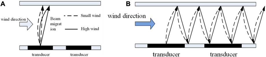
FIGURE 1. (A) Principle of ultrasonic detection of wind speed and direction; (B) principle of ultrasonic phase-shift detection of wind speed and direction.
2.2 Principle of closed-loop control modulation
To ensure that the wind sensor operates at its optimal resonance, closed-loop control modulation is required based on the principles of wind detection and the selection of resonant wavelength, where different resonance frequencies correspond to different temperatures and pressures.
In order to drive the ultrasonic transducer for frequency scanning, a closed-loop control method of frequency scanning is adopted, as shown in Figure 2, by combining the Lorentz line shape of the ultrasonic transducer at the central wavelength. In this figure, λ1 refers to the frequency spectrum line that can generate an acoustic resonance at a specific temperature and pressure (Li et al., 2013; Tang et al., 2014; Cummer et al., 2016). λ2 represents the scanning frequency of the ultrasonic transducer corresponding to λ1, and λ0 is the center frequency corresponding to the strongest resonance. The ultrasonic transducer driving voltage is scanned to achieve the frequency scanning corresponding to λ2, which covers the frequency spectrum line corresponding to λ1 so as to achieve acoustic resonance.
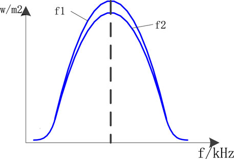
FIGURE 2. Principle of closed-loop control modulation.
To cope with resonance shifting problems, a frequency modulation signal is used as the ultrasonic transducer driving voltage. This causes a change in the sound velocity of the transducer at different temperatures and pressures, leading to a variation in the wavelength (Yang M et al., 2017). Additionally, the frequency drift of the transducer is considered when calculating the wavelength, resulting in the following formula:
Here,
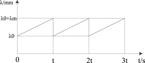
FIGURE 3. Ultrasonic transducer wavelength modulation curve.
2.3 Theoretical comparison and analysis of single and dual closed-loop control tests
The single closed-loop control method involves performing wavelength and frequency scanning across the entire temperature range. The frequency scanning range is from 30 kHz to 40 kHz, with a forward step of 100 Hz per scan. The scanning cycle is long, and after each scan is completed, the corresponding resonant frequency is re-calculated. The process is shown in Figure 4.
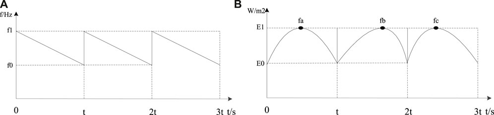
FIGURE 4. (A) Single closed-loop control modulation; (B) single closed-loop control resonance frequency shift.
In each cycle, resonance can only occur at specific frequency points due to different temperatures and pressures (Song et al., 2014; Wu et al., 2016; Long et al., 2018; Chen et al., 2019). The frequency points of each cycle will vary. As shown in the aforementioned figure, the resonance frequency point is fa in cycle 1, fb in cycle 2, and fc in cycle 3. The frequency point will shift in each cycle due to varying temperature and pressure conditions.
In practical applications, temperature changes slowly, and the single closed-loop control approach with full-range scanning can adapt to these changes. However, high wind speeds can cause rapid changes in pressure, which leads to a quick shift in the resonance frequency point during detection. To address this issue, a dual closed-loop control method is proposed (Liu et al., 2000; Li et al., 2013; Zhang et al., 2016). The method involves full-range scanning at the beginning to confirm the resonance frequency point. Afterward, a narrow-band fast scanning centered on the point is combined with full-range scanning. This approach ensures the accuracy of the resonance frequency point and can quickly follow the point in the case of rapid changes, such as high wind speeds.
2.4 Implementation approach of dual closed-loop control
To achieve the goal of dual closed-loop control, a segmented scanning approach is adopted based on the scanning characteristics of the full temperature range. This approach combines full-range scanning with narrow-range fast scanning. The schematic representation of the dual closed-loop control is shown in Figure 5.
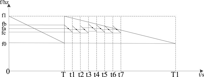
FIGURE 5. Dual closed-loop control.
During the first cycle T, a full-range scan is performed to determine the resonance frequency point fa. Once determined, a narrow-range scan from fb to fc is performed during the period from T to t1. Subsequent cycles from t1 to t2, t2 to t3, t3 to t4, t4 to t5, t5 to t6, and t6 to t7 involve fast scanning based on the frequency point to track real-time changes. Additionally, during the period from T to t1, full-range scanning is conducted to combine the narrow-range scanning with full-range scanning. After the dual closed-loop control scanning is completed, the point of the narrow-range scanning is fn and that of full-range scanning is fG.
Based on the features of the external environment, temperature changes slowly, while pressure shows a time-varying behavior. When |fn-fG|≤500 Hz, it is considered that the fast scanning is effectively tracking the point, matching the temperature and pressure conditions. Therefore, in the next scanning, the frequency resonance point will be set to fn. However, if |fn-fG|>500 Hz, it is considered that the fast scanning has shifted from the resonance frequency point due to large shifting caused by rapid changes in pressure. In this case, the next scanning will use fG as the resonance frequency point.
In the wind sensor experiment, an ultrasonic transducer with a center frequency of 40 kHz was used for scanning. The full-range scan width was 10 kHz (30 kHz–40 kHz), and the narrow-range scan width was 300 Hz. The dual closed-loop control method was able to fully achieve the desired effect (García-Chocano et al., 2012).
3 Design and structure of the wind sensor system
3.1 Overall structure diagram
The overall block diagram of the dual closed-loop controlled wind sensor system is shown in Figure 6, which includes the signal excitation unit, transceiver unit, signal processing unit, and central processing unit. The overall system structure diagram is shown in Figure 7, which includes the top cover, pressure cover, transducer-driving circuit, transducer, transducer seat, resonance cavity, signal processing circuit, and main fixed seat.
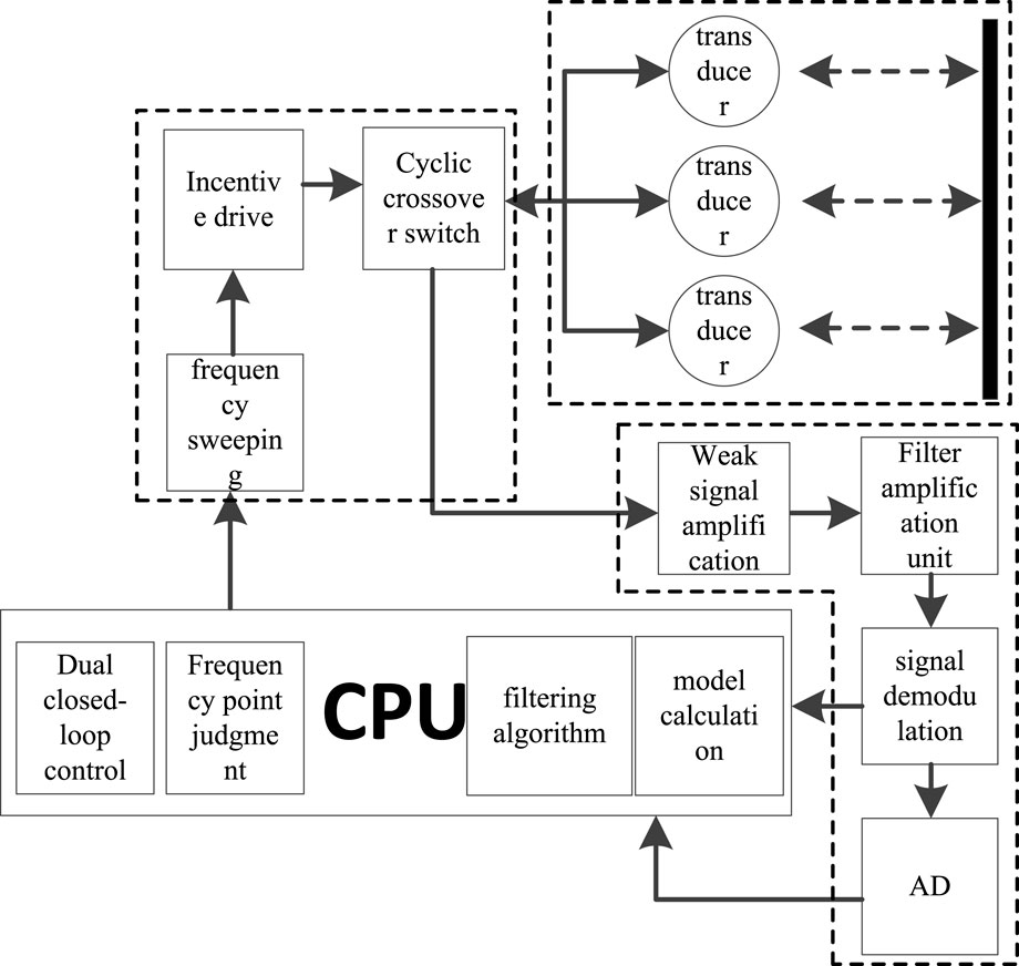
FIGURE 6. Overall block diagram of the wind sensor system.
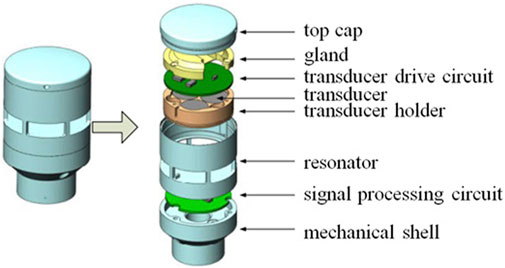
FIGURE 7. Overall structure diagram of the wind sensor system.
3.2 Design for dual closed-loop control implementation
The specific implementation of the dual closed-loop control is shown in Figure 8, which involves the following steps: full-spectrum scanning, narrow-band scanning, transducer excitation driving, and signal demodulation. The entire process of dual closed-loop control is as follows: the main control module provides a periodic signal with a specific frequency to the excitation driver, which forms a corresponding frequency driving to drive the transducer. First, the full-spectrum scanning is performed, and then, the signal demodulation is performed during the scanning. The CPU calculates the corresponding frequency point fa using the model. Subsequently, with fa as the center point, the narrow-band scan from fb to fc is performed, accompanied by full-spectrum scanning to achieve dual closed-loop control (Li et al., 2016).
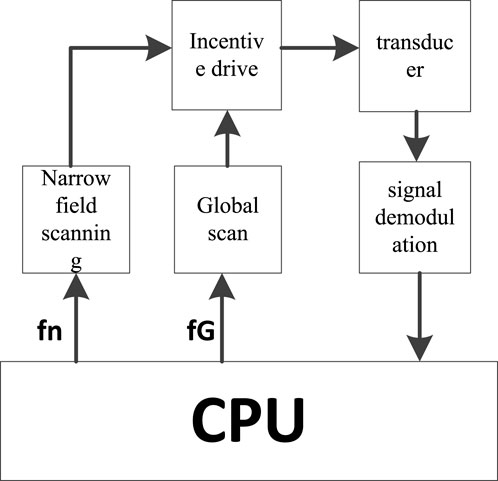
FIGURE 8. Block diagram of dual closed-loop control.
Currently, the full-spectrum scanning width of the system is 30 kHz–40 kHz, with a step of 100 Hz, and the narrow-band scanning width is fa ±300 Hz, with a step of 20 Hz.
4 Experimental test results
4.1 Comparison of results from single and dual closed-loop control tests
Experimental testing was conducted using the system introduced previously, and the voltage signal output graphs for both single-loop and double-loop control systems were observed.
The experiment’s results are presented in the following figures: Figure 9 shows the voltage signal waveform of acoustic resonance during full-domain scanning, indicating that different frequencies correspond to different amplitudes. Figure 10 shows the formation of the feedback fish-shaped waveform at the resonance frequency point. In contrast, Figure 11 shows the voltage signal waveform formed under single closed-loop control, demonstrating that single closed-loop control is incapable of forming a group of fish-shaped waveforms and is unable to track frequency changes quickly. Finally, Figure 12 shows the voltage signal waveform formed under dual closed-loop control, demonstrating the formation of a group of fish-shaped waveforms and the achievement of narrow-domain scanning. This approach can quickly track the frequency changes causing the frequency resonance point to rapidly change.

FIGURE 9. Voltage signal waveform under full-domain scanning.
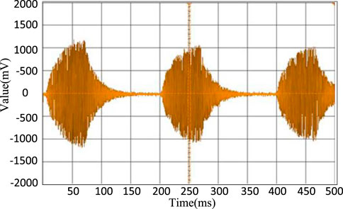
FIGURE 10. Voltage signal waveform at the resonance frequency point.
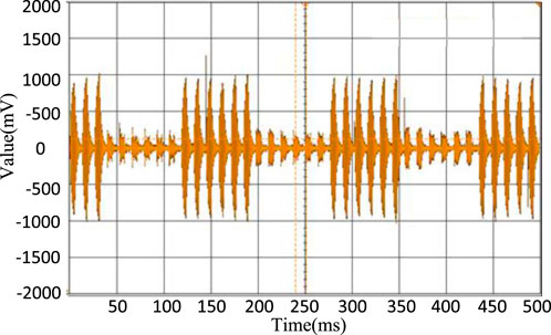
FIGURE 11. Under single closed-loop control.
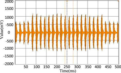
FIGURE 12. Under dual closed-loop control.
Based on the experimental results shown in the figures, it is evident that the dual closed-loop control system effectively addresses the resonance frequency point shifting caused by external changes.
4.2 Calibration experiments and result analysis of the dual closed-loop-controlled wind sensor
Tests were conducted at wind speeds of 0.00 m/s, 3.50 m/s, 10.00 m/s, 20.00 m/s, 34.00 m/s, and 50.00 m/s under the states of single closed-loop control and dual closed-loop control. For each wind speed, at least 1,000 measurements were taken, and typical values were selected for linear fitting and regression calibration, which demonstrated linear features. The corresponding digital values for each wind speed are listed in Table 1, and the fitting curves are shown in Figure 13.
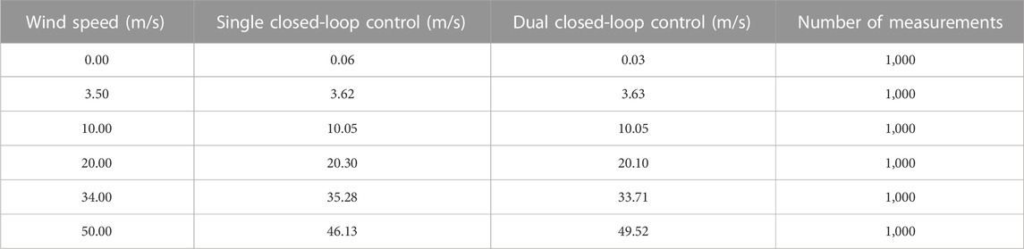
TABLE 1. Digital values corresponding to different concentrations of methane.
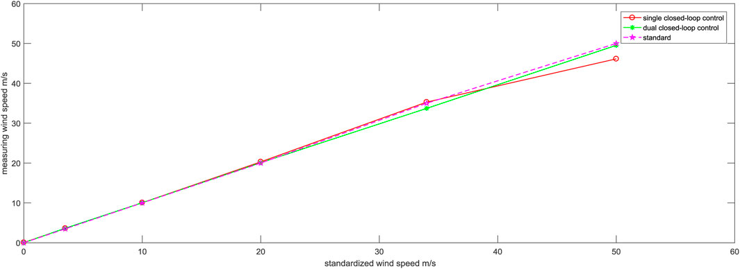
FIGURE 13. Comparison of typical values of wind speed between single and dual closed-loop control states.
The corresponding digital values under the condition of 50.00 m/s are listed in Table 2, and the trend of detection changes under the condition of 50.00 m/s is shown in Figure 14.
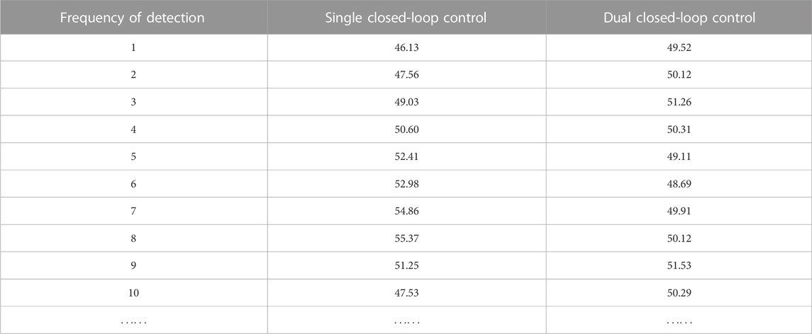
TABLE 2. Corresponding digital values at the speed of 50.00 m/s.
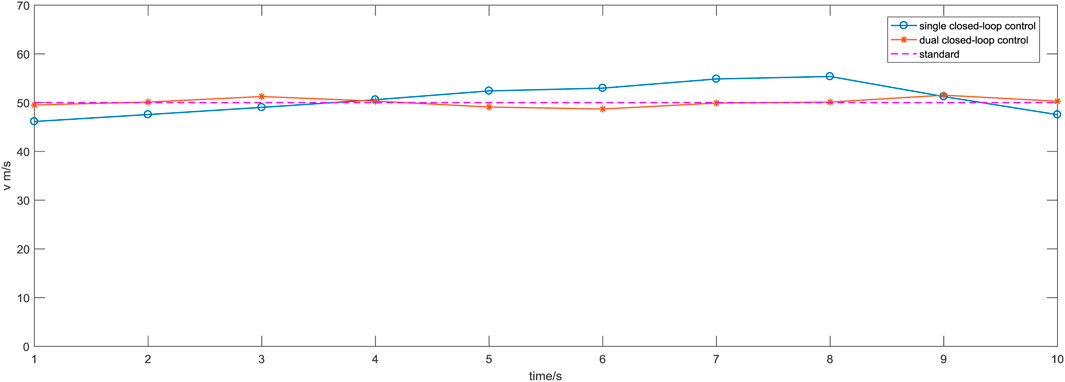
FIGURE 14. Trend of detection changes at the speed of 50.00 m/s.
Figure 13 shows that the dual closed-loop control exhibits good linearity between the measured wind speed and the standard wind speed at different wind speeds, whereas the single closed-loop control shows larger shifting from the standard line. Upon calculation, the maximum shifting corresponding to the standard wind speed is 0.96% under the dual closed-loop control, which is significantly lower than the maximum shifting of 7.74% observed in the single closed-loop control. This indicates a significant enhancement in the system’s accuracy.
Table 2 and Figure 14 show that at the wind speed of 50.00 m/s, the maximum shifting of the dual closed-loop control relative to the standard value is 3.06%, which is significantly lower than the maximum shifting of 10.47% observed in the single closed-loop control. This demonstrates that the stability of the system has been greatly improved with the implementation of dual closed-loop control.
5 Conclusion
1. The proposed dual closed-loop control method addresses the issue of resonance frequency shifting caused by environmental factors, such as pressure and temperature, and solves the problem of large wind speed measurement errors caused by the inability of frequency modulation to keep up with the rapid changes in wind shear. Compared with single closed-loop control, this method improves the wind speed detection accuracy from ±10% to ±4% and enhances the system’s adaptability to the environment. This research has improved the reliability and complexity of the wind sensor measurement model without increasing power consumption or cost.
2. By using the dual closed-loop control method, a wind sensor for better speed and direction detection was designed and tested. Experimental results show that the system using this method had good data repeatability, with a maximum relative error of 3.06%.
3. Under low wind speed conditions, the wind speed linearity is high. However, under high wind speed conditions, higher accuracy can be achieved by data compensation.
Data availability statement
The raw data supporting the conclusion of this article will be made available by the authors, without undue reservation.
Author contributions
XZ contributed to methodology, validation, software, formal analysis, investigation, resources, and writing–original draft preparation. MC and HY contributed to supervision, project administration, and funding acquisition. HY carried out conceptualization and manuscript review. All authors contributed to the article and approved the submitted version.
Funding
The research was supported by the National Nature Science Foundation of China (No. 61874015), the Chongqing Venture and Innovation Support Program for Chongqing Overseas Returnees (No. CX2019031), and the Special Key Project for Technological Innovation and Application Development in Chongqing (Nos cstc2021jscx-gksbX0045 and JG2021073).
Conflict of interest
The authors declare that the research was conducted in the absence of any commercial or financial relationships that could be construed as a potential conflict of interest.
Publisher’s note
All claims expressed in this article are solely those of the authors and do not necessarily represent those of their affiliated organizations, or those of the publisher, the editors, and the reviewers. Any product that may be evaluated in this article, or claim that may be made by its manufacturer, is not guaranteed or endorsed by the publisher.
References
Airoldi, L., and Ruzzene, M. (2011). Design of tunable acoustic metamaterials through periodic arrays of resonant shunted piezos. New J. Phys. 13 (11), 113010. doi:10.1088/1367-2630/13/11/113010
Assouar, B., Liang, B., Wu, Y., Li, Y., Cheng, J. C., and Jing, Y. (2018). Acoustic metasurfaces. Nat. Rev. Mater 3, 460–472. doi:10.1038/s41578-018-0061-4
Bruus, H., Dual, J., Hawkes, J., Hill, M., Laurell, T., Nilsson, J., et al. (2011). Forthcoming lab on a chip tutorial series on acoustofluidics: acoustofluidics—exploiting ultrasonic standing wave forces and acoustic streaming in microfluidic systems for cell and particle manipulation. Lab. Chip 11, 3579–3580. doi:10.1039/c1lc90058g
Chen, S., Fan, Y., Yang, F., Jin, Y., Fu, Q., Zheng, J., et al. (2019). Engineering coiling-up space metasurfaces for broadband low-frequency acoustic absorption. Phys. Status Solidi RRL 13, 1900426. doi:10.1002/pssr.201900426
Chen, S. B., Wang, G., Wen, J. H., and Wen, X. S. (2013). Wave propagation and attenuation in plates with periodic arrays of shunted piezo-patches. J. Sound. Vib. 332, 1520–1532. doi:10.1016/j.jsv.2012.11.005
Chen, Y., and Huang, G. (2015). Active elastic metamaterials for subwavelength wave propagation control. Acta Mech. Sin. 31, 349–363. doi:10.1007/s10409-015-0402-0
Cummer, S. A., Christensen, J., and Alù, A. (2016). Controlling sound with acoustic metamaterials. Nat. Rev. Mater 1, 16001. doi:10.1038/natrevmats.2016.1
García-Chocano, V. M., Cabrera, S., and Sánchez-Dehesa, J. (2012). Broadband sound absorption by lattices of microperforated cylindrical shells. Appl. Phys. Lett. 101, 184101. doi:10.1063/1.4764560
Hu, Y., Zhang, Y., Su, G., Zhao, M., Li, B., Liu, Y., et al. (2022). Realization of ultrathin waveguides by elastic metagratings. Commun. Phys. 5, 62. doi:10.1038/s42005-022-00843-0
Huang, H., Sun, C., and Huang, G. (2009). On the negative effective mass density in acoustic metamaterials. Int. J. Eng. Sci. 47, 610–617. doi:10.1016/j.ijengsci.2008.12.007
Leng, J., Gautier, F., Pelat, A., Picó, R., Groby, J. P., and Romero-Garcia, V. (2019). Limits of flexural wave absorption by open lossy resonators: reflection and transmission problems. New J. Phys. 21, 053003. doi:10.1088/1367-2630/ab1761
Leng, J., Romero-García, V., Pelat, A., Pico, R., Groby, J. P., and Gautier, F. (2020). Interpretation of the acoustic black hole effect based on the concept of critical coupling. J. Sound. Vib. 471, 115199. doi:10.1016/j.jsv.2020.115199
Li, J., Wang, W., Xie, Y., Popa, B-I., and Cummer, S. A. (2016). A sound absorbing metasurface with coupled resonators. Appl. Phys. Lett. 109, 2959. doi:10.1121/1.4969138
Li, X., Chen, Y., Zhang, X., and Huang, G. (2020). Shaping elastic wave mode conversion with a piezoelectric-based programmable meta-boundary. Extreme Mech. Lett. 39, 100837. doi:10.1016/j.eml.2020.100837
Li, Y., Liang, B., Gu, Z-M., Zou, X-Y., and Cheng, J-C. (2013). Reflected wavefront manipulation based on ultrathin planar acoustic metasurfaces. Sci. Rep. 3, 2546. doi:10.1038/srep02546
Liu, Z., Zhang, X., Mao, Y., Zhu, Y. Y., Yang, Z., Chan, C. T., et al. (2000). Locally resonant sonic materials. Science 289, 1734–1736. doi:10.1126/science.289.5485.1734
Long, H., Gao, S., Cheng, Y., and Liu, X. (2018). Multiband quasi-perfect low-frequency sound absorber based on double-channel mie resonator. Appl. Phys. Lett. 112, 033507. doi:10.1063/1.5013225
Nguyen, T. T., Nguyen, T. T., Duong, M. Q., and Doan, A. T. (2020). Optimal operation of transmission power networks by using improved stochastic fractal search algorithm. Neural Comput. Appl. 32 (1), 9129–9164. doi:10.1007/s00521-019-04425-0
Song, J. Z., Bai, P., Hang, Z. H., and Lai, Y. (2014). Acoustic coherent perfect absorbers. New J. Phys. 16, 033026. doi:10.1088/1367-2630/16/3/033026
Tang, K., Qiu, C., Ke, M., Lu, J., Ye, Y., and Liu, Z. (2014). Anomalous refraction of airborne sound through ultrathin metasurfaces. Sci. Rep. 4, 6517. doi:10.1038/srep06517
Thorp, O., Ruzzene, M., and Baz, A. (2001). Attenuation and localization of wave propagation in rods with periodic shunted piezoelectric patches. Smart Mater Struct. 10 (5), 979–989. doi:10.1088/0964-1726/10/5/314
Van, T. H., Van, T. L., Thi, T. M. N., Duong, M. Q., and Sava, G. N. (2021). Improving the output of dc-dc converter by phase shift full bridge applied to renewable energy. Revue Roumaine des Sci. Tech. Serie Electrotech. Energetique 66 (3), 175–180.
Wen, J. H., Chen, S. B., Wang, G., Yu, D. L., and Wen, X. S. (2016). Directionality of wave propagation and attenuation in plates with resonant shunting arrays. J. Intell. Mater Syst. Struct. 27 (1), 28–38. doi:10.1177/1045389x14560361
Wu, X., Fu, C., Li, X., Meng, Y., Gao, Y., Tian, J., et al. (2016). Low-frequency tunable acoustic absorber based on split tube resonators. Appl. Phys. Lett. 109, 043501. doi:10.1063/1.4959959
Xia, R., Shao, S., Yi, J., Zheng, K., Negahban, M., and Li, Z. (2022). Tunable asymmetric transmission of Lamb waves in piezoelectric bimorph plates by electric boundary design. Compos Struct. 300, 116111. doi:10.1016/j.compstruct.2022.116111
Xie, Y., Wang, W., Chen, H., Konneker, A., Popa, B. I., and Cummer, S. A. (2014). Wavefront modulation and subwavelength diffractive acoustics with an acoustic metasurface. Nat. Commun. 5, 5553. doi:10.1038/ncomms6553
Yang, M., Chen, S., Fu, C., and Sheng, P. (2017). Optimal sound-absorbing structures. Horiz 4, 673–680. doi:10.1039/c7mh00129k
Yin, X., Dong, L., Wu, H., Ma, W., Zhang, L., and Yin, W. (2017). Ppb-level h2s detection for sf6 decomposition based on a fiber-amplified telecommunication diode laser and a background-gas-induced high-q photoacoustic cell. Appl. Phys. Lett. 111, 1200. doi:10.1063/1.4987008
Yin, X., Wu, H., Dong, L., Ma, W., and Tittel, F. K. (2019). Ppb-level photoacoustic sensor system for saturation-free co detection of sf6 decomposition by use of a 10 w fiber-amplified near-infrared diode laser. Sensors Actuators B Chem. 282, 567–573. doi:10.1016/j.snb.2018.11.100
Zhang, H., Xiao, Y., Wen, J., Yu, D., and Wen, X. (2016). Ultra-thin smart acoustic metasurface for low-frequency sound insulation. Appl. Phys. Lett. 108, 141902. doi:10.1063/1.4945664
Keywords: dual closed-loop control, frequency modulation, frequency following, resonance frequency shift, wind speed detection
Citation: Zeng X, Chen M and Yu H (2023) Research on performance improvement of acoustic resonance-based wind sensors by using dual closed-loop control. Front. Energy Res. 11:1224047. doi: 10.3389/fenrg.2023.1224047
Received: 19 May 2023; Accepted: 29 August 2023;
Published: 25 September 2023.
Edited by:
Eldad Avital, Queen Mary University of London, United KingdomReviewed by:
Nithya Venkatesan, VIT University, IndiaMinh Quan Duong, The University of Danang, Vietnam
Copyright © 2023 Zeng, Chen and Yu. This is an open-access article distributed under the terms of the Creative Commons Attribution License (CC BY). The use, distribution or reproduction in other forums is permitted, provided the original author(s) and the copyright owner(s) are credited and that the original publication in this journal is cited, in accordance with accepted academic practice. No use, distribution or reproduction is permitted which does not comply with these terms.
*Correspondence: Hua Yu, eXVodWFAY3F1LmVkdS5jbg==
†These authors have contributed equally to this work