 Muhammad Farooq
 Ateekh Ur Rehman
 Izza Anwer3
 Muhammad Imran
- 1Research Centre for Carbon Solutions, Institute of Mechanical, Chemical and Energy Engineering, Heriot-Watt University, Edinburgh, United Kingdom
- 2Department of Industrial Engineering, College of Engineering, King Saud University, Riyadh, Saudi Arabia
- 3Institute for Transport Studies, University of Leeds, Leeds, United Kingdom
- 4Mechanical Engineering and Design, School of Engineering and Applied Science, Aston University, Birmingham, United Kingdom
- 5Sotacarbo S. P. A., Grande Miniera di Serbariu, Carbonia, Italy
Currently, the potential of biomethane derived from biogas is substantial, positioning it to fulfill a considerable share of the United Kingdom’s total energy needs. The primary challenge associated with raw biogas lies in purifying it to produce biomethane, a process that necessitates the removal of carbon dioxide and hydrogen sulfide. Among the various methods, adsorption of activated carbon (AC) stands out as a particularly effective and cost-efficient approach for converting biogas into biomethane, provided that the regeneration of AC proves economically viable. In this research, a segment of activated carbon was utilized to assess the adsorption properties when exposed to a gas mixture of CO2, H2S, and N2 within a regenerative activated carbon setup. This investigation encompassed the analysis of adsorption and desorption behaviors, process capacities, and the impact of regeneration. To enhance the adsorption of CO2, electro-conductive polymers (ECPs) were incorporated into the AC samples, leading to an extension in breakthrough time. Subsequent to adsorption, the electric potential swing desorption (EPSD) was employed for in situ regeneration of activated carbon samples, involving potentials of up to 30 V. The findings exhibited that the newly introduced EPSD technique considerably diminished desorption durations for both H2S and CO2. Moreover, it successfully rejuvenated the accessible adsorption sites, resulting in reduced desorption times compared to the initial breakthrough time during adsorption. Consequently, the EPSD system proves to be a promising candidate for in situ regeneration of activated carbon to eliminate CO2 and H2S from biogas. Notably, this approach offers inherent advantages over conventional methods including thermal swing adsorption (TSA) and pressure swing adsorption (PSA) in terms of regeneration. The demonstrated method underscores the potential for more efficient and economically viable cycles of adsorption and desorption, thereby enhancing the overall biogas-to-biomethane conversion process to achieve SDGs 7 and 13 for clean and green energy applications.
1 Introduction
Biogas has emerged as a promising renewable energy source, boasting of abundant availability, cost-effectiveness, and positive environmental attributes. It results from the anaerobic digestion of organic materials like agricultural waste, municipal solid waste, and wastewater sludge, yielding a gas mixture consisting of methane (CH4), carbon dioxide (CO2), and minor amounts of hydrogen sulfide (H2S), ammonia (NH3), and water vapor (H2O) (Zhao et al., 2023a; Zhao et al., 2023b; Feng et al., 2023). Nonetheless, the presence of impurities, particularly CO2 and H2S, impedes its utilization as a clean energy resource (Farooq et al., 2017; Yuan, J et al., 2023).
Biogas upgradation to biomethane usually involves the removal of CO2, H2S, and other non-methane gases and adjusting the calorific value to make biomethane compatible with fossil natural gas (NG) and liquefied natural gas (LNG), as shown in Table 1 (Cheah et al., 2016). Biomethane typically consists of 86%–96% CH4, 2%–6% CO2, and H2S <10 ppm and can be used in vehicles or injected in national natural gas grids (Ghafoori 2021). In comparison, NG and LNG have H2S contents well below 1 ppm since an H2S level even below 2 ppm is toxic to the nervous system of humans and corrosive to the equipment including engines and pipes and causes multiple environmental issues (Díaz et al., 2015). The concentration of CO2 and H2S in biogas varies with the AD feedstocks, and the concentration of H2S is high in sewerage and agriculture and animal waste, where it ranges from 600 ppm to 20,000 ppm, as compared to municipal and landfill waste, where it varies from 3 ppm to 3,000 ppm (Kanjanarong et al., 2017). The necessity to reduce the CO2 and H2S concentration to be in compliance with grid injection standards is a challenge (Memetova et al., 2022). Hence, for many European countries, the H2S concentration in biomethane is allowed to be 5–10 ppm, which is significantly higher than that typical for NG or LNG. According to ISO 15403:2006 and the European Association for the Streamlining of Energy Exchange-gas (EASEE), H2S is allowed up to <5 mg/m3 for the natural gas and up to <3.3–5 mg/m3 for LNG, but it is typically below 1 ppm in practice due to issues caused by its odor. For biomethane, different European countries generally allow significant H2S levels, where UK, Austria, Belgium, France, Denmark, Holland, and Germany have levels typically ≤5 mg/m3, whereas Italy has a level of ≤6.6 mg/m3, Poland and the Czech Republic ≤7 mg/m3, and Brazil and Sweden ≤10 mg/m3 (Svensson et al., 2019). The Wobbe Index (WI) in Table 1 also of biomethane is less than that of LNG and NG. The WI of biomethane is low compared to that of LNG and NG because of a higher CO2 content since the allowed CO2 quantity ranges from 2%–6%. The Wobbe Index is the main indicator of the interchangeability of fuel gases and is frequently defined in the specifications of gas supply and transport utilities (Molino et al., 2013).
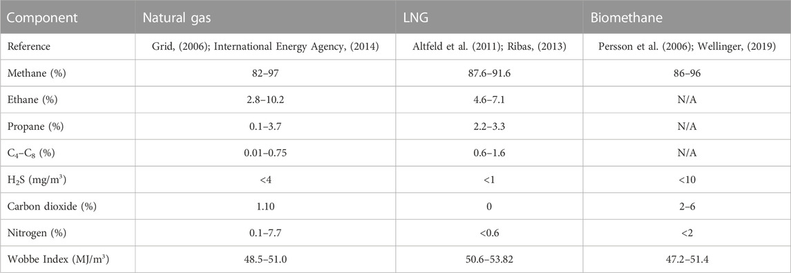
TABLE 1. Typical commercial natural gas, LNG, and biomethane composition.
The commercial technologies used for biogas upgradation are mainly absorptive and adsorptive processes, as well as processes based on membrane filtration or cryogenic separation. These established techniques are facing significant challenges in terms of energy consumption and operating costs, which may add substantial costs to the upgraded gas (Papurello et al., 2022).
The main barrier for increased biogas utilization is its upgradation to biomethane, where elimination of CO2 and H2S is required (Weiland, 2020; Rasi et al., 2011; Farooq et al., 2012; Bai et al., 2023). These are Renewable Heat Incentives (RHIs) that provide 7.5 p/KWh to the producers of biomethane of all capacities (Jenkins et al., 2016). In recent times, carbon capture and adsorbent regeneration methods have garnered significant attention for their potential to enhance biogas purification efficiency and mitigate CO2 emissions. Carbon capture technologies encompass the separation and extraction of CO2 from biogas, offering possibilities for applications like enhanced oil recovery, carbon utilization, and sequestration (Chinea et al., 2023; Zhang et al., 2021). Adsorbent regeneration methods involve the restoration of spent adsorbents, which can be reused post-regeneration, thereby reducing purification costs (Tinnirello et al., 2020).
Hydrogen sulfide stands as a noxious and corrosive gas, formed naturally in the anaerobic digestion process that yields biogas. With a distinctively pungent odor, H2S poses risks to human wellbeing, inducing respiratory and neurological complications at elevated levels (Papurello et al., 2014). Furthermore, unaddressed H2S within biogas can induce complications downstream, notably within power generation and heating systems. Combusting biogas containing H2S results in sulfur dioxide (SO2) formation, a prime contributor to acid rain and a potent greenhouse gas. Furthermore, H2S can initiate corrosion within equipment and pipelines involved in biogas handling, transportation, and utilization (Tang et al., 2023). Consequently, the elimination of H2S from biogas serves two primary purposes: safeguarding human health and averting environmental contamination.
Numerous techniques exist for H2S removal from biogas, with method selection contingent upon diverse factors encompassing H2S concentration, flow rate, temperature, and intended biogas application downstream (Tabish et al., 2022). Collectively, expunging H2S from biogas is a pivotal step to ensure the secure and efficient harnessing of biogas as a renewable energy source, while simultaneously mitigating its adverse environmental consequences.
The cost of biogas upgradation shows that the cost of biogas cleaning reduced with the increase in the plant capacity (Svensson et al., 2019). These values were used for the comparison analysis of biomethane production by activated carbon adsorption (Jiang et al., 2022). The total projected capital and operating costs with the activated carbon equates to a reduction of 17.3% and 64.5%, respectively, which shows the economic viability of this method. The cost of the upgrade is significantly reduced by the physical adsorption of activated carbon. Hence, there is a strong political drive toward decreasing the cost of biomethane production.
To render biogas suitable for fuel applications, a purification process is vital for impurity removal. Various biogas purification techniques, spanning physical, chemical, and biological methods, have been developed to address this issue. Among these methods, adsorption stands out as a highly effective and widely employed approach, not only eliminating impurities but also enabling the recovery of valuable components from biogas. Physical adsorption by activated carbon bed is the most attractive and convenient desulfurization method (Evangelisti et al., 2015). Hence, adsorption by activated carbon (AC) could be an efficient and economical approach because activated carbon is a cost-effective material compared to other adsorbents like alumina, silica, and zeolites (Farooq et al., 2020; Xi et al., 2021). Activated carbon has risen to prominence as a remarkably efficient and widely utilized adsorbent for carbon capture. With its extensive porosity and substantial surface area, activated carbon offers an ideal platform for capturing CO2 from flue gases and other sources. This adsorption process has attributes of efficiency, cost-effectiveness, and environmental compatibility (Roque-Malherbe 2007; Wang et al., 2023). Derived from diverse carbonaceous sources like coal, coconut shells, and wood, activated carbon undergoes chemical treatment and high-temperature processing for the development of its porous structure. This structure, characterized by a significant surface area, greatly enhances the adsorption process. The material’s pronounced affinity for CO2 renders it an exceptional choice for capturing this gas from high-CO2-content flue gases. The reversibility of the adsorption process makes it reusable, contributing to its efficiency and cost-effectiveness. A notable benefit of employing activated carbon lies in its versatility, allowing customization for specific applications. Adjusting the pore size, surface area, and chemical composition can augment activated carbon’s adsorption capacity, making it adaptable to diverse industrial requirements. Another advantage of activated carbon is its ability to concurrently capture other pollutants alongside CO2. Its substantial porosity and surface area enable the capture of sulfur dioxide (SO2), nitrogen oxides (NOx), and other contaminants, extending its utility beyond carbon capture. Furthermore, activated carbon boasts of advantages such as affordability, straightforward regeneration, and compatibility with various processing conditions (Farooq et al., 2021). Its eco-friendliness stems from its renewable origin and the potential for regeneration and recycling. Activated carbon stands as a versatile and effective adsorbent for carbon capture. Its remarkable surface area, customizable properties, and positive environmental attributes position it favorably for a range of industrial applications. Continued development of activated carbon in the context of carbon capture is poised to play a significant role in reducing greenhouse gas emissions and addressing climate change concerns (Farooq et al., 2017).
This paper presents a comprehensive overview of biogas purification techniques, with a specific focus on carbon capture and adsorbent regeneration methods. It delves into adsorption and regeneration techniques by evaluating their efficacy in eliminating biogas impurities. In the present research, the adsorption and desorption analyses of carbon dioxide and hydrogen sulfide were conducted separately with the help of regenerative activated carbon rigs. The activated carbon sample was first loaded with the H2S gas mixture. Adsorption with repeated loading was analyzed to observe the effect of recyclability and consistency of the adsorbent. The breakthrough times, volume, and capacities of AC were determined at normal conditions. Following the adsorption process, desorption was carried out with low electric potentials of 0, 10, 20, and 30 V and purging with nitrogen gas. Data of complete adsorption/desorption cycles were used for the comparison of repeated adsorption and the effect of desorption with and without the electric potentials. Accordingly, desorption kinetics were compared with the adsorption breakthrough time to analyze the need for additional adsorption/desorption columns.
2 Materials and methods
Table 2 summarizes the characteristics of the activated carbon sample, for which the surface area, elemental, and proximate analyses were conducted. The proximate analysis of the activated carbon sample was performed. The proximate composition of the AC sample is 9.57% water, as it can be seen that when the temperature increases to 100°C from 25°C, there is a weight loss of approximately 10%. The VM was observed at 81% of the sample weight %, whereas the content of the remnant was 19.83%, which is the ash content present in the sample. The amount of fixed carbon was calculated by subtracting all the content from 100, which was 60.2% for the AC sample.
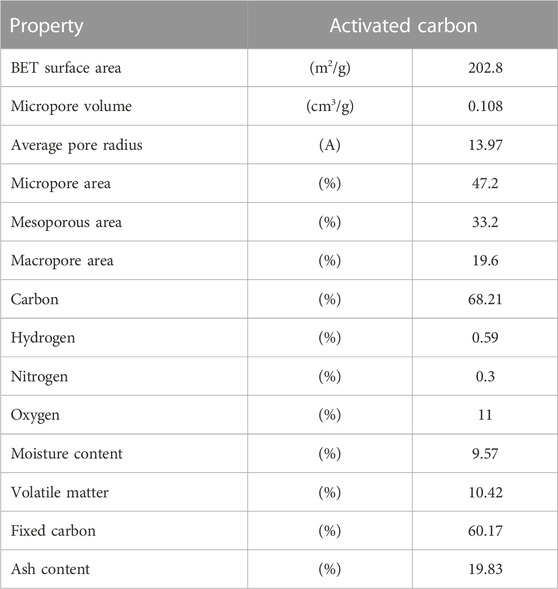
TABLE 2. Characteristics of activated carbon.
The CO2 and H2S adsorption and desorption analyses with the activated carbon samples were conducted in a packed-bed regenerative activated carbon column, as shown in Figure 1. The gas manifold system comprises three different lines each fitted with volume flowmeters ranging from 1 to 100 mL/min. The first line was used to feed in the inert gas, nitrogen. The other two lines were used to feed in CO2 and 1% H2S/99% N2, in order to use the different gas mixtures. These gases were mixed at the next joint to vent in the mass spectrometer (MS). Valves V-1 and V-2 were installed before and after the regenerative activated carbon rig to control the input gas for the MS, which was further attached with mass software, where these gases were quantified. Due to safety reasons, the 1 vol% hydrogen sulfide/99 vol% nitrogen gas mixture was placed inside the fume hood, where the gas was connected through a pipe connection with the apparatus. The system was equipped with a mass spectrometer with mass software for continuously analyzing the gas. The concentration of hydrogen sulfide and nitrogen was analyzed before and after the activated carbon rig.
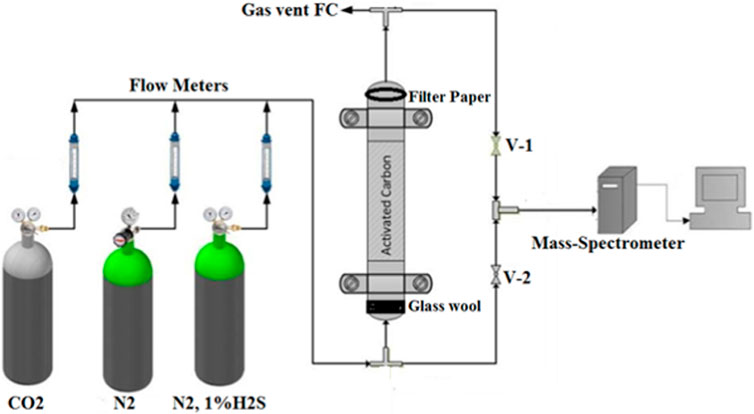
FIGURE 1. Experimental setup of the regenerative activated carbon unit (Farooq et al., 2017).
3 Results and discussions
3.1 Effect of adsorption and repeated loading on activated carbon at different temperatures of 25°C, 50°C, and 75°C
Figure 2 compares the effect of repeated loading of the activated carbon sample at different temperatures of 25, 50°C, and 75°C. It was carried out in the TGA with continuous adsorption and desorption cycles, where nitrogen was used for desorption and carbon dioxide for adsorption. This time a different protocol was used compared with the previous TGA process of the AC sample. Initially, the sample was heated at 100°C to remove any moisture content from the sample. The temperature was then decreased to 25°C for the first adsorption cycle, where the adsorption occurred at 93.6% and desorption occurred at 89.2%. This corresponds to the weight % difference of the TGA profile for AC loading at 25°C temperature. Similar values of adsorption and desorption were observed upon repetition for the second and third cycles at the same temperature. The temperature in the TGA was increased from 25°C to 50°C to analyze the repeated loading behavior at an increased temperature. It was observed that the adsorption and desorption curve showed a reduction as compared to that at 25°C. The weight drop for adsorption was 91.68% for 50°C, which is approximately 2% less than that occurred at 25°C. Desorption also decreases at 88.6% as compared with 89.2% at 25°C. These adsorption desorption cycles were repeated twice at the same temperature. The temperature of the sample was then further increased to 75°C. Adsorption was decreased as the temperature increased, which was 3.75% and 1.64% less compared to that at 25°C and 50°C, respectively. This confirms the adsorption decrease with the increase in the temperature (Sreńscek-Nazzal et al., 2016). However, the recyclability for the same temperature was observed very close. It gives very smooth curves at different temperatures and repeated loading for the same sample. Initially, the baseline was observed at 88 wt% at 100°C, which was established to an increased value of 89.1% at a lower temperature of 25°C. This baseline was observed as 88.6% and 88.2% at 50°C and 75°C, respectively, which means that the temperature profile is necessary for determining the baseline. To achieve the baseline with the dried sample, the temperature needs to be increased, which was carried out at the start of the adsorption–desorption profiles in the TGA analysis.
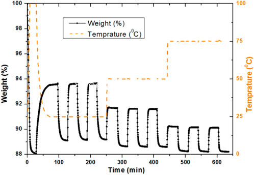
FIGURE 2. Effect of repeated loading of AC at different temperatures of 25°C, 50°C, and 75°C.
3.2 Effect of adsorption and desorption for combined CO2 and H2S in the experimental rig with activated carbon
Figure 3 compares the co-adsorption and desorption analysis of CO2 and H2S in the activated carbon rig with the AC sample at normal conditions. The process of H2S adsorption was too long with a low volume flow rate, which is why due to safety reasons, it was not possible to run H2S for long hours. CO2 was considered the base for the comparison purpose. Cycles were operated at different timings, but the experimental conditions taken were the same. Since the adsorption and breakthrough of H2S was observed longer than for CO2, separate vertical axes were used for both gases. Furthermore, the horizontal axis used was graded in minutes instead of seconds for the unit of time because a number of repetitions of CO2 were carried out until it reached the breakthrough point for H2S. Breakthrough of the CO2 was observed after 8.5 min. After the breakthrough of CO2, the adsorption curve shows an increase with the same pattern, which was previously observed. However, H2S keeps on adsorbing with the AC sample. CO2 reached its maximum saturated level in approximately 40 min, whereas the adsorption was continued for approximately 1 h and H2S was continuously adsorbed. The desorption process was started after approximately 1 h of adsorption to observe the behavior of both gases. Desorption was carried out for approximately 30 min for most of the CO2 desorbed, whereas a very small amount of H2S was desorbed. This is because there was no H2S supply during desorption and only N2 was used during desorption. After 30 min of desorption, the next cycle of adsorption was started with the same conditions, whereas H2S continued adsorption and CO2 proceeded with the same steps of breakthrough and adsorption. The second, third, and fourth adsorption cycles were carried out for approximately 30 min, 30 min, and 60 min, respectively, whereas desorption was carried out for approximately 30 min, 50 min, and 50 min, respectively, during these cycles. This repetition was continued until the fifth adsorption cycle, when H2S breakthrough starts after 172 min of the adsorption time. Breakthrough and adsorption and desorption properties of CO2 are comparable because of the same flow rate of the gas used, as 25 mL/min was used earlier.
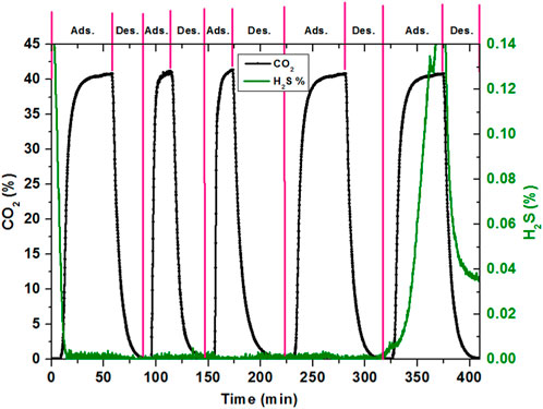
FIGURE 3. Combined effect of CO2 and H2S with AC in the adsorption rig.
However, this could not be the case for the breakthrough time of H2S separately adsorbed and desorbed since a flow rate of 14 mL/min of H2S was used here, whereas in the earlier section, the maximum H2S concentration was measured at a flow of 90 mL/min. From the combined adsorption and desorption cycle, it could be concluded that the CO2 and H2S adsorbed and desorbed on the AC independently and did not have much interference with the surfaces of both gas molecules.
3.3 Effect of CO2 desorption at 0, 10, 20, and 30 V potentials with the AC sample
Figure 4A compares the effect of the regeneration of the exhausted AC sample at different low potentials of 0, 10, 20, and 30 V. Nevertheless, this carbon has a higher adsorption capacity and low desorption times and by applying electric potentials, the desorption becomes quicker. However, for a more specific data analysis, there is a need to discuss the normalized rate of desorption. Figure 4B compares the normalized rate of desorption of the AC sample from 0 to 30 V potentials. At C/C0 = 0.2, the no potential system and a 10 V potential were observed to be almost similar, whereas the 20 V and 30 V potentials were fast compared with the 0 V potential. However, the effect of these desorptions overlapped until C/C0 = 0.5, and it is clear that the potentials’ effect is increasing smoothly with the increasing potential values. The desorption rate of the AC sample was observed to be quicker. The complete desorption rate shows that with a 30 V potential, it takes approximately 1,000 s, whereas the no potential system takes about double the time for complete desorption. However, the desorption rates in general are not sufficient to get a clear idea about the overall desorption. It could be helpful in explaining the behavior at 50% and 90%.
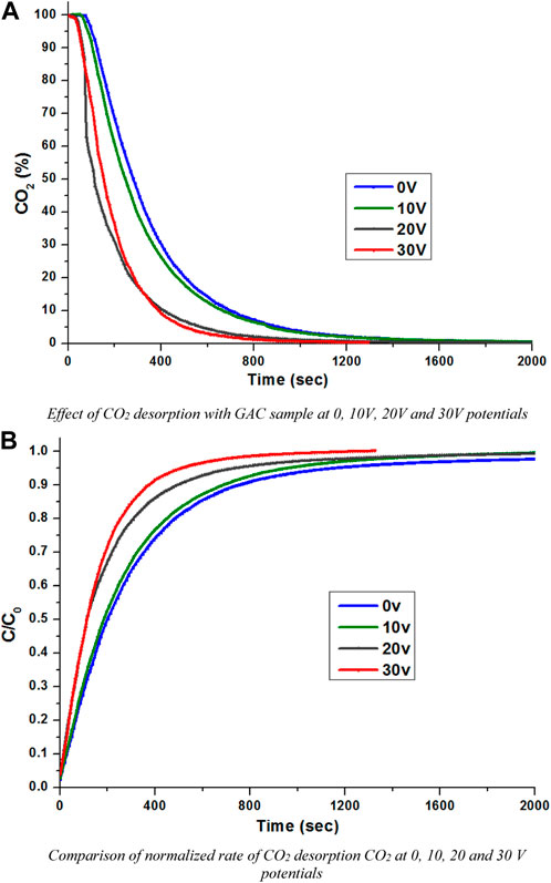
FIGURE 4. (A) Effect of CO2 desorption with the GAC sample at 0, 10, 20, and 30 V potentials. (B) Comparison of the normalized rate of CO2 desorption at 0, 10, 20, and 30 V potentials.
3.4 Effect of 50% desorption for H2S at 0, 10, 20, and 30 V potentials with the AC sample
Figure 5 compares the H2S desorption rate at C/C0 = 0.5 for the potentials of 0, 10, 20, and 30 V. The pattern shows a great shift when desorption switched to the potential mode. It was observed that 50% desorption without potentials occurred at approximately 1,600 s, which reduced to approximately 100% of the time of desorption for the 10 V potential, with 832 s. The potential was increased to 20 V, which shows a further 9.1% decrease in desorption time compared with 10 V. The potential was increased to 30 V, which shows a further reduction in desorption time, which was observed at 704 s. This shows that applying potentials on the regenerative activated carbon system greatly helps the desorption behavior of H2S. The 90% desorption time without a potential occurred at approximately 6,700 s, which reduced to 3,130, 2,210, and 2,185 s for a potential of 10, 20, and 30 V, respectively.
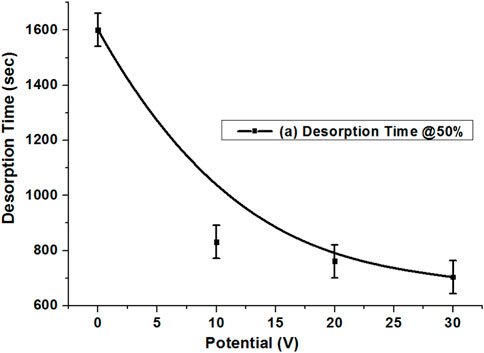
FIGURE 5. 50% desorption of the AC sample with H2S at 0, 10, 20, and 30 V potentials.
3.5 Effect of 50% and 90% desorption of CO2 at 0, 10, 20, and 30 V potentials with the AC sample
For the specific observation of the desorption behavior of the AC sample, the normalized desorption rates were plotted at 50% and 90%. This is important for estimating how much time is required at these particular points. Figure 6A compares the desorption rate, which was explicitly drawn for the different low potentials at C/C0 = 0.5, that shows a very smooth decrease in time with the increase in potentials. However, it was different compared with the extruded carbon sample. At the 50% desorption rate, the time reduction for the AC sample was slower when applying low potentials compared with the no potential system, whereas the AC sample shows smooth behavior from 0 to 30 V.
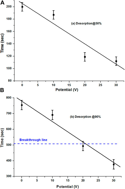
FIGURE 6. (A) 50% and (B) 90% desorption of the AC sample with CO2 at 0, 10, 20, and 30 V potentials.
Figure 6B compares the 90% desorption rate of the AC sample at 0, 10, 20, and 30 V. With different potential values, it gives a very good smooth relation in terms of the reduction of desorption time with the increase in potentials. Especially with the 20 and 30 V potentials, desorption against the adsorption breakthrough results in a good desorption rate. An interesting point is that the breakthrough point of adsorption time was achieved within the low potentials’ system and with the increase in potentials, the time reduced further. It could be reduced further with the increase in the potentials’ system, whereas the breakthrough time was slightly less in the case of the 90% desorption of the extruded sample at 30 V as well, which was because of the high adsorption time of the sample. With 30 V desorption being observed at approximately 380 s, the breakthrough time was approximately 510 s, which means that it occurred even before the breakthrough time, which is great.
3.6 Effect of AC desorption at mixing ratios of 0, 25, 50, 75, and 100% with ECPs
Figures 7A, B compare the effect of the desorption of AC with different mixing ratios of 0, 25, 50, 75, and 100% with ECPs. For the AC100 and ECP100, the previously calculated values were used, which were 187 and 130 s, respectively, at C/C0 = 0.5. The 50% desorption showed an increase in the desorption time compared with the AC100 as 52%, 56%, and 15% for the ECP mixing of 25, 50, and 75% with the AC sample, respectively. The time for the 90% desorption was reduced to 8%, 12%, 37%, and 45% with the addition of 25, 50, 75, and 100% of ECPs in the AC sample, respectively. The 90% desorption shows a fast desorption with the mixing of ECPs with the AC sample. At C/C0 = 0.9, the average desorption value of non-mixed AC and ECPs was calculated as 585 s, whereas the same desorption was observed as being 11% slower with the AC50ECP50 sample. This desorption was observed without any effect of the potential, so the analysis with the potential may affect desorption with different mixing values, which could be analyzed separately.
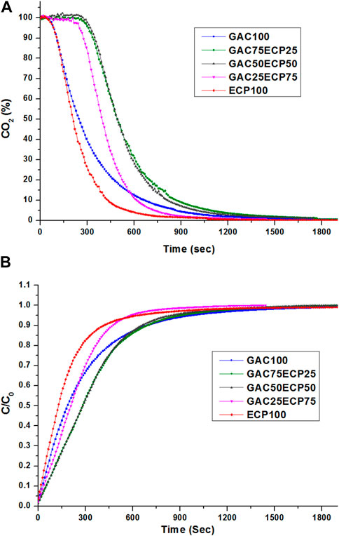
FIGURE 7. Mixing of AC desorption at mixing ratios of 0, 25, 50, 75, and 100% with ECPs. (A) Effect of desorption. (B) Effect of the normalized desorption rate.
3.7 Effect of 90% desorption reduction of the 0 and 30 V potential of AC with different mixing ratios of ECPs
Figure 8 compares the effect of 90% desorption reduction of AC mixing with ECPs at different ratios of 25, 50, and 75% from the 0 V potential to the 30 V potential. The AC sample was observed to have the maximum reduction in 90% desorption with 50% reduction in desorption time, whereas the ECP sample only decreased by 4.4%. The other mixed samples AC75ECP25, AC50ECP50, and AC25ECP75 had 16%, 10%, and 3% reduction in desorption time, respectively. This may be because of the packing issue in the fixed bed which caused this behavior of desorption. This confirms that the potential profile of ECPs did not help in desorption.
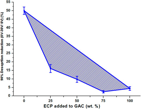
FIGURE 8. Effect of 90% desorption reduction of AC mixing with ECPs from 0 to 30 V potential.
4 Conclusion
The present research was established for to propose an effective and new method for in situ regeneration of activated carbon with electric potential swing desorption (EPSD) for the upgradation of biogas to biomethane. For this purpose, a regenerative activated carbon rig was installed in the laboratory and a commercial activated carbon referred to as AC was used. The baseline study of the AC sample was conducted using EA, BET, and TGA and proximate analyses. For the in situ regeneration of activated carbon, the AC sample was observed as the best suitable sample for regeneration using EPSD, which resulted in a reduction in desorption time compared to the no potential system. It is therefore concluded that EPSD desorption of H2S and CO2 is an effective method for the regeneration of activated carbon compared with the non-potential system. In general, activated carbon holds promise as a versatile and efficient substance for carbon capture uses. However, its actual performance and appropriateness for a given application are contingent upon the unique conditions and requirements of that particular situation.
Data availability statement
The original contributions presented in the study are included in the article/Supplementary Material; further inquiries can be directed to the corresponding authors.
Author contributions
MF: resources, writing–review and editing, conceptualization, formal analysis, investigation, methodology, validation, visualization, and writing–original draft. AR: resources, writing–review and editing, funding acquisition, project administration, and supervision. IA: data curation, formal analysis, software, validation, and writing–review and editing. MI: investigation, methodology, project administration, and writing–review and editing. AP: data curation, formal analysis, software, validation, and writing–review and editing. JA: conceptualization, funding acquisition, investigation, project administration, resources, supervision, visualization, and writing–review and editing.
Funding
The author(s) declare that financial support was received for the research, authorship, and/or publication of this article. This research was funded by the Deputyship for Research and Innovation, Ministry of Education in Saudi Arabia, through grant number (IFKSUOR3-079-2).
Acknowledgments
The authors extend their appreciation to the Deputyship for Research and Innovation, “Ministry of Education” in Saudi Arabia, for funding this research (IFKSUOR3-079-2).
Conflict of interest
The authors declare that the research was conducted in the absence of any commercial or financial relationships that could be construed as a potential conflict of interest.
Publisher’s note
All claims expressed in this article are solely those of the authors and do not necessarily represent those of their affiliated organizations, or those of the publisher, the editors, and the reviewers. Any product that may be evaluated in this article, or claim that may be made by its manufacturer, is not guaranteed or endorsed by the publisher.
References
Altfeld, K., Schley, P., and Ruhrgas, E. (2021). “Development of natural gas qualities in Europe,” in European journal of gas technologies, distribution and applications (GNF International).
Bai, X., Zhang, S., Li, C., Xiong, L., Song, F., Du, C., et al. (2023). A carbon-neutrality-capacity index for evaluating carbon sink contributions. Environ. Sci. Ecotechnology 15, 100237. doi:10.1016/j.ese.2023.100237
Cheah, W. Y., Ling, T. C., Juan, J. C., Lee, D. J., Chang, J. S., and Show, P. L. (2016). Biorefineries of carbon dioxide: from carbon capture and storage (CCS) to bioenergies production. Bioresour. Technol. 215, 346–356. doi:10.1016/j.biortech.2016.04.019
Chinea, L., Slopiecka, K., Bartocci, P., Alissa Park, A. H., Wang, S., Jiang, D., et al. (2023). Methane enrichment of biogas using carbon capture materials. Fuel 334, 126428. doi:10.1016/j.fuel.2022.126428
Díaz, I., Ramos, I., and Fdz-Polanco, M. (2015). Economic analysis of microaerobic removal of H 2 S from biogas in full-scale sludge digesters. Bioresour. Technol. 192, 280–286. doi:10.1016/j.biortech.2015.05.048
Evangelisti, S., Lettieri, P., Clift, R., and Borello, D. (2015). Distributed generation by energy from waste technology: a life cycle perspective. Process Saf. Environ. Prot. 93, 161–172. doi:10.1016/j.psep.2014.03.008
Farooq, M., Bell, A. H., Almustapha, M., and Andresen, J. M. (2017). Bio-methane from an-aerobic digestion using activated carbon adsorption. Anaerobe 46, 33–40. doi:10.1016/j.anaerobe.2017.05.003
Farooq, M., Chaudhry, I., Hussain, S., Ramzan, N., and Ahmed, M. (2012). Biogas up gradation for power generation applications in Pakistan. J. Qual. Technol. Manag. VIII (II), 107–118.
Farooq, M., Saeed, M. A., Imran, M., Uddin, G. M., Asim, M., Bilal, H., et al. (2020). CO2 capture through electro-conductive adsorbent using physical adsorption system for sustainable development. Environ. Geochem. health 42, 1507–1515. doi:10.1007/s10653-019-00318-2
Farooq, M., Soudagar, M. E. M., Imran, M., Arslan, M., Tariq, M. S., Pettinau, A., et al. (2021). Carbon capture for sustainable environment in developing countries. Energy Environ. Secur. Dev. Ctries. 2021, 525–544. doi:10.1007/978-3-030-63654-8_21
Feng, X., Wang, B., Gao, G., Gao, S., Xie, C., and Shi, J. (2023). MnyCo3−yOx bimetallic oxide prepared by ultrasonic technology for significantly improved catalytic performance in the reduction of NOx with NH3. Fuel 352, 129159. doi:10.1016/j.fuel.2023.129159
Ghafoori, M. S., Loubar, K., Marin-Gallego, M., and Tazerout, M. (2022). Techno-economic and sensitivity analysis of biomethane production via landfill biogas upgrading and power-to-gas technology. Energy 239, 122086.
Jenkins, N., Long, C., and Wu, J. (2016). An overview of the smart grid in great britain. Engineering 1 (4), 413–421. doi:10.15302/j-eng-2015112
Jiang, J., Zhang, L., Wen, X., Valipour, E., and Nojavan, S. (2022). Risk-based performance of power-to-gas storage technology integrated with energy hub system regarding downside risk constrained approach. Int. J. Hydrogen Energy 47 (93), 39429–39442. doi:10.1016/j.ijhydene.2022.09.115
Kanjanarong, J., Giri, B. S., Jaisi, D. P., Oliveira, F. R., Boonsawang, P., Chaiprapat, S., et al. (2017). Removal of hydrogen sulfide generated during anaerobic treatment of sulfate-laden wastewater using biochar: evaluation of efficiency and mechanisms. Bioresour. Technol. 234, 115–121. doi:10.1016/j.biortech.2017.03.009
Memetova, A., Tyagi, I., Karri, R. R., Kumar, V., Tyagi, K., Suhas, V., et al. (2022). Porous carbon-based material as a sustainable alternative for the storage of natural gas (methane) and biogas (biomethane): a review. Chem. Eng. J. 446, 137373. doi:10.1016/j.cej.2022.137373
Molino, A., Migliori, M., Ding, Y., Bikson, B., Giordano, G., and Braccio, G. (2013). Biogas upgrading via membrane process: modelling of pilot plant scale and the end uses for the grid injection. Fuel 207, 585–592.
Papurello, D., Lanzini, A., Leone, P., Santarelli, M., and Silvestri, S. (2014). Biogas from the organic fraction of municipal solid waste: dealing with contaminants for a solid oxide fuel cell energy generator. Waste Manag. 34 (11), 2047–2056. doi:10.1016/j.wasman.2014.06.017
Papurello, D., Silvestri, S., Biasioli, F., and Lombardi, L. (2022). Wood ash biomethane upgrading system: a case study. Renew. Energy 182, 702–712. doi:10.1016/j.renene.2021.10.037
Persson, M., Jönsson, O., and Wellinger, A. (2006). Biogas upgrading to vehicle fuel standards and grid injection. IEA Bioenergy task.
Rasi, S., Läntelä, J., and Rintala, J. (2011). Trace compounds affecting biogas energy utilisation–A review. Energy Convers. Manag. 52 (12), 3369–3375. doi:10.1016/j.enconman.2011.07.005
Ribas, S. J. M. R. X. (2013). LNG blue corridors project - European commission seventh framework programme (FP7). Avaliable at: http://lngbluecorridors.eu/.
Sreńscek-Nazzal, J., Narkiewicz, U., Morawski, A. W., Wróbel, R. J., and Michalkiewicz, B. (2016). “The increase of the micoporosity and CO2 adsorption capacity of the commercial activated carbon CWZ-22 by KOH treatment,” in Microporous and mesoporous materials (InTech).
Svensson, M., Petersson, A., and Held, J. (2019). “Renewable methane–an important aspect when establishing a more diversified sourcing and distribution of energy gas in Sweden,” in 24th world gas conference (Sweden: Swedish Gas Centre).
Tabish, A. N., Patel, H. C., Mani, A., Schoonman, J., and Aravind, P. V. (2022). Effect of H2S and HCl contaminants on nickel and ceria pattern anode solid oxide fuel cells. Electrochimica Acta 423, 140592. doi:10.1016/j.electacta.2022.140592
Tang, Y., Wu, A., Liu, W., Pei, W., Guan, W., and Singhal, S. C. (2023). Anti-poisoning performance of flat-tube solid oxide fuel cell in high concentration H2S environment. Energy Rep. 9, 5915–5921. doi:10.1016/j.egyr.2023.05.026
Tinnirello, M., Papurello, D., Santarelli, M., and Fiorilli, S. (2020). Thermal activation of digested sewage sludges for carbon dioxide removal from biogas. Fuels 1 (1), 30–46. doi:10.3390/fuels1010004
Wang, B., Gupta, R., Bei, L., Wan, Q., and Sun, L. (2023). A review on gasification of municipal solid waste (MSW): syngas production, tar formation, mineral transformation and industrial challenges. Int. J. Hydrogen Energy 48, 26676–26706. doi:10.1016/j.ijhydene.2023.03.086
Weiland, P. (2020). Biogas production: current state and perspectives. Appl. Microbiol. Biotechnol. 85 (4), 849–860. doi:10.1007/s00253-009-2246-7
Wellinger, A. (2019). Standards for biomethane as vehicle fuel and for injection into the natural gas grid. report within the IEE project “GreenGasGrids”.
Xi, M., Fu, X., Yang, H., He, C., Fu, L., Cheng, X., et al. (2021). Predicted a honeycomb metallic BiC and a direct semiconducting Bi2C monolayer as excellent CO2 adsorbents. Chin. Chem. Lett. 33, 2595–2599. doi:10.1016/j.cclet.2021.12.041
Yuan, J., Wang, T. J., Chen, J., and Huang, J. A. (2023). Microscopic mechanism study of the creep properties of soil based on the energy scale method. Front. Mater. 10, 1137728. doi:10.3389/fmats.2023.1137728
Zhang, S., Bai, X., Zhao, C., Tan, Q., Luo, G., Wang, J., et al. (2021). Global CO2 consumption by silicate rock chemical weathering: its past and future. Earth's Future 9 (5), e1938E–e2020E. doi:10.1029/2020EF001938
Zhao, G., Li, Z., Cheng, B., Zhuang, X., and Lin, T. (2023a). Hierarchical porous metal organic framework aerogel for highly efficient CO2 adsorption. Sep. Purif. Technol. 315, 123754. doi:10.1016/j.seppur.2023.123754
Keywords: biogas, activated carbon, electric potential, in situ regeneration, physical adsorption
Citation: Farooq M, Rehman AU, Anwer I, Imran M, Pettinau A and Andresen JM (2023) Towards net-zero: CO2 capture and biogas purification through electric potential swing desorption to achieve SDGs 7 and 13. Front. Energy Res. 11:1276733. doi: 10.3389/fenrg.2023.1276733
Received: 12 August 2023; Accepted: 17 October 2023;
Published: 01 November 2023.
Edited by:
Kirsten Heimann, Flinders University, AustraliaReviewed by:
Davide Papurello, Polytechnic University of Turin, ItalyAbdul-Sattar Nizami, Government College University, Lahore, Pakistan
Copyright © 2023 Farooq, Rehman, Anwer, Imran, Pettinau and Andresen. This is an open-access article distributed under the terms of the Creative Commons Attribution License (CC BY). The use, distribution or reproduction in other forums is permitted, provided the original author(s) and the copyright owner(s) are credited and that the original publication in this journal is cited, in accordance with accepted academic practice. No use, distribution or reproduction is permitted which does not comply with these terms.
*Correspondence: Muhammad Farooq, ZW5ncmZhcm9vcTEzN0BnbWFpbC5jb20=; Ateekh Ur Rehman, YXJlaG1hbkBrc3UuZWR1LnNh