 Ahmed G. Khairalla1
 Hossam Kotb1*
 Kareem M. AboRas1
 Muhammad Ragab1
 Hesham B. ElRefaie1
 Yazeed Yasin Ghadi2
 Amr Yousef3,4*
- 1Department of Electrical Power and Machines, Faculty of Engineering, Alexandria University, Alexandria, Egypt
- 2Department of Computer Science and Software Engineering, Al Ain University, Abu Dhabi, United Arab Emirates
- 3Engineering Mathematics Department, Faculty of Engineering, Alexandria University, Alexandria, Egypt
- 4Electrical Engineering Department, University of Business and Technology, Jeddah, Saudi Arabia
Large-scale energy storage systems (ESSs) that can react quickly to energy fluctuations and store excess energy are required to increase the reliability of electricity grids that rely heavily on renewable energy sources (RESs). Hybrid systems, which combine different energy storage technologies such as batteries and supercapacitors, are becoming increasingly popular because no single technology can satisfy all requirements. In this study, a supercapacitor is used to stabilize quickly shifting bursts of power, while a battery is used to stabilize gradually fluctuating power flow. This paper proposes a robust controller for managing the direct current (DC) bus voltage to optimize the performance of ESS. The proposed controller combines a fractional-order proportional integral (FOPI) with a classical PI controller for the first time in the DC microgrid area. The hybrid (FOPI-PI) controller achieves an outstanding and superior performance in all transient and dynamic response specifications compared to other traditional controllers. The parameters of the suggested controller are incorporated with the self-adaptive bonobo optimizer (SaBO) to determine the optimal values. Furthermore, various optimization techniques are applied to the model and the SaBO’s output outperforms other techniques by minimizing the best objective function. In addition, the current study has utilized a novel power management strategy that includes two closed current loops for both batteries and supercapacitors. By using this method, batteries’ lifespans may be increased while still retaining optimal system performance. The suggested controller is implemented in MATLAB/Simulink 2022b, and the outcomes are reported for several case studies. The findings demonstrate that the control technique remarkably improves the transient response, such as transient duration, overshoot/undershoot, and the settling time. The proposed controller (FOPI-PI) with the SaBO optimizer is effective in maintaining the DC bus voltage under load and solar system variation.
1 Introduction
1.1 Background and motivation
DC microgrid technology is becoming more popular since it is able to link renewable sources of energy, electrical needs, and ESSs. Due to its ability to create a decentralized, sustainable power system grid with minimal carbon emissions, distributed power generating research has grown quickly as a result (Gu et al., 2023). The inherent unpredictability of renewable energy sources (RES) and the shifting patterns of energy demand over time make it difficult to guarantee a dependable power supply. The intermittent nature of RES, like solar and wind energy, adds unpredictability to the process of producing electricity (Song et al., 2022; Liao et al., 2023). ESSs can help solve problems caused by the fact that green energy sources don’t always work. Finding a single solution that can satisfy all unique criteria is difficult due to the vast range of characteristics and features of ESSs. Considerations for power-energy ratings, drainage, and load are crucial for choosing the best ESS for a given application. Utilize a mix of technologies and tailored approaches to satisfy a range of functional needs and guarantee the effectiveness of the energy storage system (Chen, 2022; Shao et al., 2023). As a feasible resolution to this problem, systems that store energy using a mix of electrical technologies have been put forward. These technologies integrate several EES components, relying on the strengths of each while effectively addressing their limitations through comprehensive system management (Kim et al., 2017). Moreover, there are several innovative EES configurations utilized, such as Flywheel Energy Storage (FES), Superconducting Magnetic Energy Storage (SMES), Supercapacitors, and Batteries. This technology provides excellent efficiency, a quick response time, a longer cycle life, high power density, fast charging and draining, and low self-discharge (Kim et al., 2020). Batteries are frequently used as energy storage units in microgrid applications, despite their restricted potential to deliver high power during transient events due to their extended charging and discharging periods (Zuo et al., 2017). In situations that involve elevated levels of demand, the battery’s response time declines, resulting in increased load and diminished lifespan of the battery. In order to address this matter, supercapacitors (Sup-Cs) have been developed. Sup-Cs provide useful features for ESS performance optimization and power surge management. They are appropriate for high-power applications because of their quick charging and discharging rates for huge amounts of energy, and because they act as an energy buffer to control power flow and prolong battery life (Raghavendra et al., 2020a). Hence, the integration of the ESS technologies with favorable attributes, such as a hybrid configuration comprising both batteries and Sup-Cs, can yield advantages in terms of both fast dynamic responsiveness and prolonged power delivery (Jing et al., 2018a).
1.2 Literature review
A thorough examination of the various topologies and contemporary uses of battery and Sup-C combo systems was conducted by (Jing et al., 2018b; Uloom et al., 2022). In addition, several hybrid electrical energy storage (HEES) approaches and control strategies have been presented to mitigate HEES defects to achieve a better dynamic response in many applications (Koohi-Fayegh and Rosen, 2020). Ref (Hacini et al., 2023) discussed a controller using a mechanism that incorporates a reversible chopper between the batteries and Sup-C with the DC bus to provide a steady voltage on the DC bus to provide improved energy management and supply continuity. A conventional PI controller was implemented for the incorporation between Sup-Cs and batteries so as to store solar power (Kollimalla et al., 2014). Furthermore, the authors of (Chong et al., 2017) proposed a strategy for managing energy dynamically in HESS that applied to renewable power generation. For better transient characteristics, the authors of (P et al., 2020) put together power management features with a classic PI controller. The Self-Organizing Map-Particle Swarm Optimization (SOM-PSO) method being suggested for the Battery-SCs HEES involves utilizing a power distribution algorithm that incorporates both charging and discharging thresholds. This approach aims to enhance the system’s versatility and flexibility (Chong et al., 2018). The system covered in (Laldin et al., 2013; Liu et al., 2023) concentrates on energy management and EV charging control inside a station linked to a hybrid power system. The system intends to maximize energy usage, improve renewable energy integration, and achieve efficient operation by merging various RES and efficiently controlling the solid oxide fuel cell with electrolyzer subsystem. Due to fluctuations in electrical properties and unidentified external disturbances, which unavoidably worsen the control performance of the HESS, uncertainty is inescapable in system modeling. In order to mitigate the negative impacts and increase control precision, this work adopts a novel adaptive dynamic surface control with disturbance observers underlying tracking in the HESS (Xiao et al., 2021; Zhang et al., 2022; Min et al., 2023). The authors of (Pa et al., 2014) introduced a technique for examining the dynamic reaction of the PV power-generating system that consists of a bidirectional charger/discharger and a standalone battery. In addition, the complete power conditioning architecture of the stand-alone solar system includes a DC-link voltage regulator scheme that takes advantage of storage current during operation without connecting to an external power source. Moreover, The scheduling of a battery storage system in a hybrid wind-PV plant has been optimized using a mixed receding horizon control strategy (Alramlawi et al., 2018; Yang et al., 2019). In order to achieve the optimum charge/discharge rates of the battery with SC, an EMS for DC standalone has been presented in (Gugulothu et al., 2023a). The charge/discharge rate constants of HESS were determined using a Jaya-based optimization method for the given fluctuations of the PV/load power. The EMS approach that has been suggested in (Gugulothu et al., 2023b) is intended to increase the dependability and lifespan of the batteries while lowering hydrogen consumption. The deep charging of the battery under low demand is avoided in the suggested EMS by using the PV system de-rating approach. Utilizing a reverse sigmoidal function of the battery’s state of charge (SoC), the fuel cell power supply is modulated. This increases the hydrogen fuel’s efficiency and lessens the battery’s deep discharge in situations of high loading. The aim of (Ongaro et al., 2012; Şahin and Blaabjerg, 2020) was to investigate the energy management system of a wireless sensor network using photovoltaic energy. The system comprises the integration of Sup-Cs and a lithium-ion battery as a hybrid electrical energy storage (HEES) system. A method for controlling the voltage magnitude of the load bus in a DC power system that consists of a standalone PV panel and batteries, with a constant power load is introduced by (Bhagiya and Patel, 2019). The proposed approach uses a two-loop proportional-integral (PI) control strategy based on pulse width modulation (PWM). The inner loop controller is responsible for managing the inductor current. Conversely, the outer loop controller is responsible for controlling the load bus voltage. Furthermore (Al-Saadi et al., 2021; Guentri et al., 2021), contributes to the development of a control strategy that integrates PV and ESS in DC micro-grids while also accounting for fluctuating loads and solar radiation. The control strategy of the Grid Side Voltage Source Converter ensures a constant DC voltage in both grid-connected and isolated modes, allowing for optimal utilization of PV power under various operating conditions. Following this trend, the Enhancement of management of a DC microgrid that includes solar panels as RES and batteries for energy storage by utilizing a voltage source converter (VSC) control system is discussed in (Emara et al., 2021; Al et al., 2023). The work has been developed in (Prathikantham and Somlal, 2023) using a meta-heuristic optimization approach to suggest a probabilistic neural network-based EMS design for a freestanding microgrid. The design’s main objective was to balance the demand while controlling the start-up and shutdown of the diesel generator, maximizing the use of solar resources, and maintaining the State of Charge (SOC) of the batteries and super capacitor within safe limits. The study (Boumediene et al., 2023) has suggested that an electric scooter powered by a combination of battery and supercapacitor sources. In order to fulfill load needs during braking and counter-loading, maintain the battery and supercapacitor at their ideal states of charge (SOC), and increase the independence of the energy system, a fuzzy logic-based control method for energy management is created.
1.3 Contribution
In this study, a novel control architecture that is a combination of Fractional-order proportional integral (FOPI) and PI controller is implemented to maintain the stability and resilience of the interconnected DC microgrids. The proposed controller parameters can be tuned by the self-adaptive Bonobo Optimization algorithm (SaBO). The distinct contributions of this study can be clearly highlighted in the following important points when compared to prior research:
• An innovative control strategy is introduced, merging the fractional-order Pi with classical PI, for regulating the power of the solar panels, batteries, and the Sup-C. As a result, better stability, steady-state performance, robustness, and enhanced transient response could be achieved.
• The proposed (FOPI-PI) controller is incorporated with a recent optimization algorithm called the self-adaptive bonobo optimizer (SaBO) to tune the parameters of the controller. This proposed technique is utilized for the first time in DC microgrids.
• The performance of SaBO is influenced by memory, previous experiences, and a novel repulsion-based learning technique for adjusting parameters. Additionally, the algorithm also incorporates four different mating techniques: promiscuous, restrictive mating, consortship, and extra-group mating.
• Furthermore, compared to the classical PI controller established in (Guentri et al., 2021), the proposed (FOPI-PI) controller’s performance obviously overcomes the PI controller in the major aspects including the transient repose characteristics such as transient time, steady-state error and overshoot/undershoot.
• This research comprehensively compares three controllers and four optimization techniques. The simulation part also runs three cases including load fluctuation and solar system variation (Temperature and Solar irradiance). Thus, the existing investigations show the improved performance of the suggested control methodology.
The paper is structured as follows: Section 2 describes the overall system’s configuration and modeling. Section 3 presents the proposed control strategy, which includes the DC bus scheme, proposed controller, and PMS strategy. Moreover, Section 4 introduces the developed optimization technique (SaBO) and its different strategies. Section 5 discusses the simulation results in detail, covering solar irradiance and load variations. Finally, Section 6 provides the conclusions and the outcomes of the study.
2 Structure and modeling of the PV panels with hybrid batteries and Sup-Cs system
A solar PV system coupled to the DC bus via a bidirectional DC-DC converter (BDC) is shown in Figure 1 as the studied PV system proposal. The EES is composed of batteries and SCs, with each of them coupled to the DC bus through a BDC. The PV system provides the main source of DC power to a load, while the battery is utilized during instances of power surplus or deficit. Additionally, the charge controller (SC) is employed to regulate fluctuations in either the PV system or the load. The Maximum Power Point Tracking (MPPT) is utilized to harvest the maximum power from the PV via the BDC, while each BDC is regulated by a FOPI-PI controller. The entire system is managed through a highly effective power management strategy (PMS). PMS regulates the power flow between the HEES system and the solar system to meet the load power.
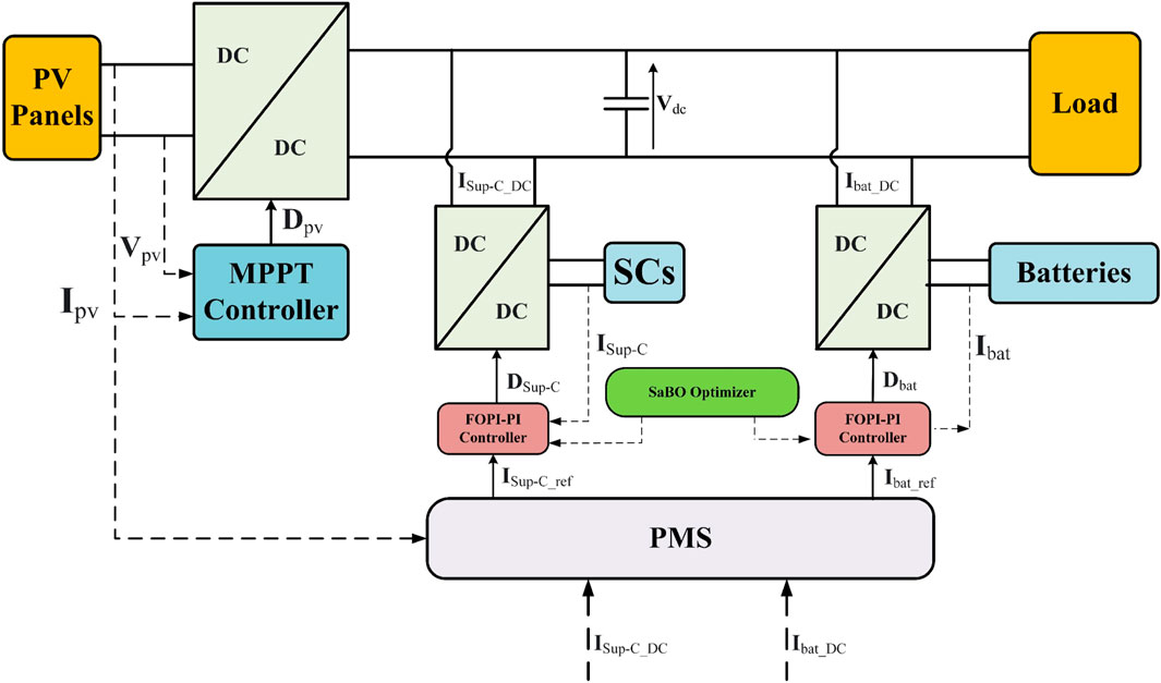
FIGURE 1. Block diagram of the proposed PV model with hybrid ESS.
2.1 Modeling of PV panel
The calculated I-V and P-V characteristics of a PV cell are determined by means of exact formulas in the proposed model. Various models have been applied by researchers, utilizing a range of parameters ranging from one to five. The five-parameter model is well recognized and esteemed, particularly when applied in outdoor settings (Humada et al., 2018). Figure 2 illustrates the implementation of the PV model based on the single-diode representation (Humada et al., 2020). The model for a PV cell includes several components, where Iph represents the current generated by sunlight, ID is the diode current, and Ish stands for the shunt-leakage current. Additionally, Ipv is the output current provided by the panel, and Rs is the series resistance that is affected by the depth of the p-n junction (Zaouche et al., 2017).
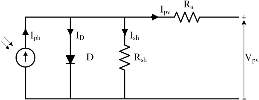
FIGURE 2. Single-diode model of a PV module.
Applying Kirchhoff’s Current Law for the above circuit results in:
The final relationship of a solar panel output current can be expressed by Eq. 2 (Kumar and Kumar, 2017):
where Is represents the saturation current, Vt represents the thermal voltage, q represents the electron charge (q = 1.60217 × 10⁻¹⁹ C), k is the Boltzmann’s constant (k = 1.38065 × 10⁻²³ J/K), Tc indicates the operating temperature, and A represents a factor which range typically varies from 1 to 2 (Mendalek and Al-Haddad, 2017).
Tref refers to the reference temperature of the cell, and Gr represents the solar insulation. A PV array is created by connecting many PV modules in series and parallel combinations to reach the required current and voltage levels (Cherukuri et al., 2022). The resulting output current (Ipv) can be calculated by Eq. 4 (Aidoud et al., 2019).
The parameters of the PV module utilized in this model are presented briefly in Table 1.
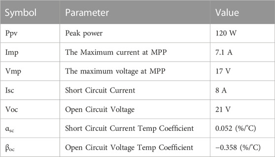
TABLE 1. Parameters of PV module WU-120.
2.2 Characteristics of the batteries
In PV applications, the battery model shown in Figure 3 is thought to be the most widely used. The configuration consists of an ideal battery with a terminal voltage Vt, an internal resistance Rin, the open circuit voltage Vo, and an internal resistance Rin (Thakkar, 2021).
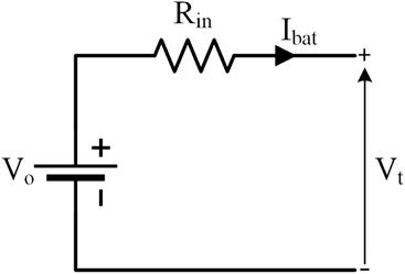
FIGURE 3. Equivalent circuit of Lithium-ion battery.
The Ampere-hour (Ah) counting method could be considered a simple and computationally efficient technique to estimate the battery’s state of charge (BSOC) and could be mathematically explained as shown in Eq. 5.
2.3 Configuration of the bidirectional DC-DC converter (BDC)
The basic BDC is depicted in Figure 4. The typical buck and boost converter’s unidirectional switches are swapped out for bidirectional power switches to create this converter. The end product is a BDC that works as a boost converter from Vs to Vdc and as a buck converter in the opposite way (Gorji et al., 2019).
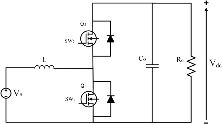
FIGURE 4. Bidirectional DC-DC converter Model.
Q1 is always turned off in the buck converter mode, and current flows from the DC bus to the batteries and Sup-Cs system. To charge the HEES, lower the voltage across the DC bus by changing Q2 according to Eq. 6.
By contrast, Q2 is turned off in the boost mode, allowing current to flow from the HEES to the DC bus only in one direction. The converter may increase the potential of the HESS by adjusting the duty cycle of Q1 as shown in Eq. 7 (Raghavendra et al., 2020b).
3 Architecture of the proposed control strategy
This section illustrates a detailed representation of the overall proposed control system, used in this paper, including the DC bus control, the suggested hybrid controller, the current control loops, and the power management strategy (PMS).
3.1 DC bus control
The DC bus is an essential component of a PV system because it transfers power from the PV array to the load. The DC bus control system has the responsibility of managing the power flow between the PV array, HEESS, and the load to optimize HEESS charging and discharging.
The control block diagram utilized for the regulation of the DC bus voltage, denoted as Vdc, is presented in Figure 5. To create the current Idc_ref, a hybrid controller (FOPI-PI) is employed. The PMS then utilizes this reference current to compute the reference currents for the batteries and Sup-C control loop, represented by IBat_ref and ISup-C_ref, respectively. It is necessary to control current references of BDC to achieve this goal (Zeraati et al., 2018).
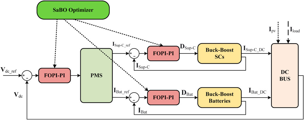
FIGURE 5. Block diagram of the proposed DC bus control strategy.
3.2 Proposed hybrid (FOPI-PI) controller
The controller that is being discussed uses both fractional-order PI and standard PI words. This makes it different from the typical FOPI controller because it combines the best parts of both. Enhanced control performance is achieved using mixed fractional-order PI and PI controllers as they accurately capture the process dynamics leading to precise control. Moreover, the mixed controller offers increased stability and robustness against modeling errors and system disturbances. Rapid and smooth system response is also attained due to the mixed controller’s ability to reduce settling times and minimize overshot and oscillations. Additionally, the proposed controller is less sensitive to changes in process parameters compared to traditional PID controllers (Ram Babu and Chandra Saikia, 2019; Altbawi et al., 2023). The schematic diagram of the proposed controller is represented in Figure 6.
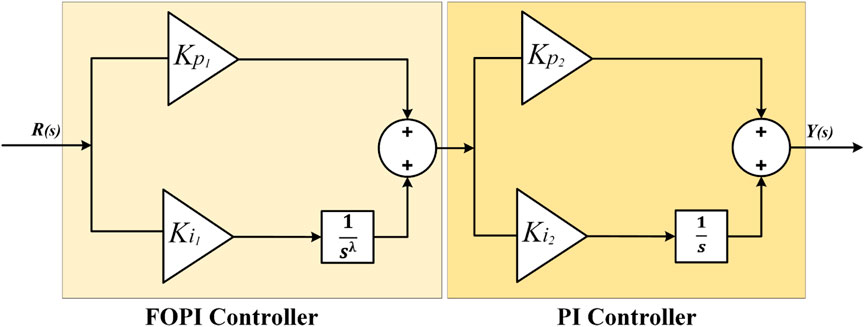
FIGURE 6. Structure of the proposed hybrid controller.
The transfer function (TF) of the FOPI-PI controller can be described by Eq. 8.
where Kp1, Ki1, and
3.3 Current controllers design of the HEES system
The control loop for the DBC of the Sup-Cs is shown in Figure 7A. Sup-C reference current ISup-C_ref is generated by the controller’s voltage control loop (Abdullah et al., 2013). GSup-C represents the TF of the Sup-C as in Eq. 9.
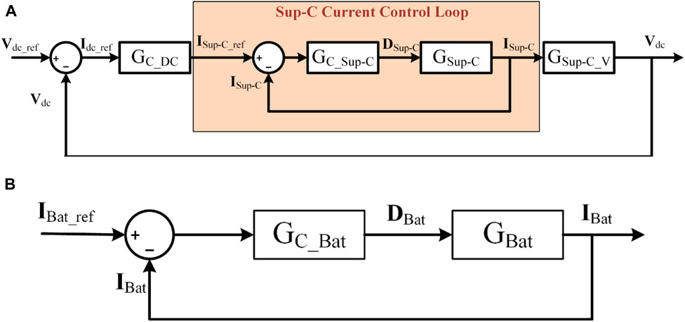
FIGURE 7. The Proposed FOPI-PI Control loop of the (A) Sup-C and (B) the batteriers.
G C_Sup-C represents the TF of the (FOPI-PI) that controls the SCs’ current as described by:
As presented, the TF for controlling the Sup-C current is dependent on several parameters, including the DC bus capacitor (C), the DC bus resistance (R), the BDC inductance (L sc), the Sup-C voltage (Vsc), and the duty ratio (Dsc) (P et al., 2020).
The TF of the DC bus control loop compensator can be expressed as in Eq. 11.
The voltage control loop which transfers the Sup-C current to the voltage signal can be obtained by:
Similar to the SCs, the control loop of the BDC of the battery is depicted in Figure 7B.
GBat represents the Batteries’ transfer function as described by:
GC_Bat represents the (FOPI-PI) transfer function that controls the Batteries’ current as given by:
As previously stated, the transfer function for controlling the batteries’ current relies on several parameters, including the DC bus capacitor (C), the DC bus resistance (R), the BDC inductance (LBat), the potential of the batteries (VBat), and the duty ratio (DBat).
In general, the batteries’ reference current is given by:
These standard currents are used to keep the DC bus voltage stable when the load on the solar panels or the power taken from them changes.
3.4 Power management strategy
A new and straightforward control strategy has been developed and evaluated for HESS (Kumar Kollimalla et al., 2014). The suggested methodology utilizes batteries to handle gradual changes in power surges, while Sup-Cs are used to manage rapid changes. By transitioning power surges into Sup-Cs, this method can overcome the obstacle of the slow battery time response. Additionally, this approach improves the lifespan of the batteries by implementing charge/discharge rate control to reduce current stresses. The main concept of this strategy is the achievement of coordination between the batteries and the SCs. In case the power extracted from by the PV system is less than the power required by the load (Pload), and at the same time, the batteries are unable to compensate for the difference, then Sup-Cs will discharge. Conversely, when the power developed by the solar system is greater than the required by the load, and the batteries are unable to quickly store the excess power, the Sup-Cs will start to charge. Figure 8 shows the overall strategy of all possible cases for the regulation process of the DC bus voltage.
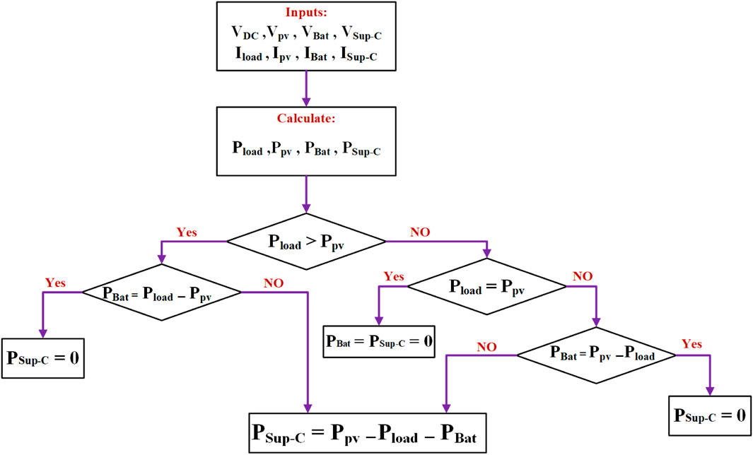
FIGURE 8. Strategy of power management of the DC bus.
The proposed control strategy is illustrated in Figure 9. This algorithm aims to minimize the pressure on the batteries during charging and discharging cycles, thereby increasing the battery’s lifespan. It is assumed that the SOC of the batteries remains within an acceptable range at all times. The algorithm works by comparing the average value of Vdc with a reference voltage (Vref), and afterward, the error has proceeded to a proposed (FOPI-PI) controller. The total current (ΔI) represents the output signal of the proposed controller. Eq. 6 introduces the combined current that needs to be provided by the (HESS), which includes both the batteries and SCs.
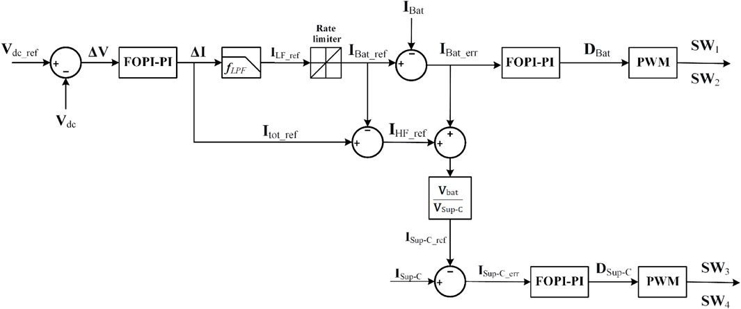
FIGURE 9. Hybrid energy storage system control scheme.
According to the frequency, the reference current Itot_ref is split into a low-frequency component (ILF_ref) and a high-frequency component (IHF_ref). On one hand, the (ILF_ref) is fulfilled by the batteries, after the rate-limiting process, could be achieved using a low-pass filter. On the other hand, (IHF_ref) could be satisfied by the SCs. The low-frequency component could be defined as:
where fLPF is the low-pass filter TF. The batteries’ reference current can be expressed as Eq. 13.
where fRL is the rate limiter TF.
The proposed control strategy involves comparing the
Meanwhile, the high-frequency component of the total current can be given by:
Due to the battery’s slightly poor response time, it may not instantaneously align with the reference current (
To balance the uncompensated battery power, the control strategy sets a reference current for the Sup-C using Eq. 21 as follows:
The control strategy involves comparing the reference current for the Sup-Cs (
4 Self-adaptive bonobo optimization algorithm
The Self-Adaptive Bonobo Optimization Algorithm (SaBO) is an evolutionary optimization algorithm. It is based on how bonobos mate and behave in social situations. SaBO is characterized by its ability to adaptively adjust its search parameters based on the performance of the population, enabling it to successfully strike an equilibrium between exploration and execution. To produce descendants, bonobos utilize four fundamental mating strategies: consortship, restricted, promiscuous, and extra-group mating. SaBO is especially useful for tackling issues involving complex, nonlinear search zones that are challenging for conventional optimization methods to explore (Das and Pratihar, 2019). The SaBO is a population-based method that uses random population initialization and a fixed population size. The fitness values of all bonobos are computed based on the solution, which is referred to as a bonobo in the population. The alpha bonobo (αbon), which holds the highest rank within a bonobo community’s social structure, is selected based on its superior fitness value relative to other bonobos in the population. Consequently, it is presently regarded as the optimal choice. The SaBO parameters are also set to their default values contemporaneously with this procedure. Moreover, bonobos go between the positive and negative phases of their phase probability (pp), indicating either population diversity or selective pressure (Das and Pratihar, 2019). SaBO makes the major two controlling parameters: pp and sharing co-efficient (β). The aforementioned parameters have the ability to adjust autonomously and undergo updates during iterations through the utilization of repulsion-based learning. This approach is entirely dependent on the values collected from the search process. Both the variables pp and β can take values within the interval of 0–1. In each cycle, we give N, the number of solutions, to pp or β from the current population. These parameters’ values are anticipated to vary from one value to another. First, we generate N of these parameters, each with a mean (μ) and standard deviation
Figure 10 illustrates the process of updating the phase probability (pp) based on the repulsion technique according to Eq. 22.
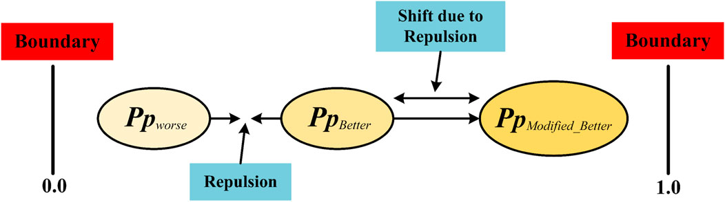
FIGURE 10. Repulsion-based learning method for pp update.
4.1 Creating new bonobos using various mating techniques
The phase probability (pp) parameter determines the mating behavior of bonobos. The value of (pp) is initially set to 0.5 and is modified after each iteration.
4.1.1 Promiscuous and restrictive mating strategies
The new generation of bonobos by promiscuous and restrictive mating approaches are created according to Eq. 23.
where the new_boni represents the ith-new solution. Moreover, boni, bonp, and bonk1 are the present population’s ith, pth, and k1th solutions, respectively. Similarly, oldpopk2 and oldpopk3 are k2th and k3th solutions, respectively. Badpopk4 is the k4th solution of the badpop population, which is the third memorized population. The value of βi is the ith-sharing coefficient. It should be noticed that k1, k2, k3, and k4 are four separate values chosen at random from the range (1, N) (Das and Pratihar, 2019).
4.1.2 Extra-group mating strategy
Extra-group mating is used to update the solution if the random number is equal to or less than the probability of extra-group mating (pxgm) through Eqs 24–26.
Co is an intermediary parameter. R1 and r2 are two distinct random numbers generated in the range (0 upto1). new_bonji and new_bonji are the jth variables of the given solution and the existing population’s ith bonobo, respectively (Farh et al., 2022).
4.1.3 Consortship mating strategy
When the value of r2 is larger than the value of (pxgm), the consortship mating strategy is used to generate new offspring. Eqs 27–31 demonstrate this process.
C1,C2, C3 and
4.2 Modified boundary handling technique
The generated bonobo is given a value equal to the maximum bound when it crosses the top variable limit with a probability of occurrence of 0.5. If not, it is changed with a 50% chance using Eqs 32, 33.
Similarly, the same Equations are used to adjust a new bonobo if it is determined that it exceeds the lower variable boundaries.
The steps of the Implementation of the SaBO can be summarized as follow:
• Initialization of parameters and population size of the SaBO.
• Comparison of all bonobos’ fitness levels.
• Identification of the αbon.
• Choose the pth bonobo randomly from good solutions.
• Is a random number (0, 1) ≤ pp?
• If this is the case, use the promiscuous or restricted mating technique to make a new bonobo.
• If false, use the consortship or extra group mating technique to make a new generation.
• Calculate the fitness values of new bonobos, as well as the alpha bonobo.
• Update the memorized parameters of populations using the repulsion-based learning method.
• Sorting of the mixed population based on fitness.
• Calculate and display the objective function.
Figure 11 depicts the flowchart outlining SaBO’s solution procedures.
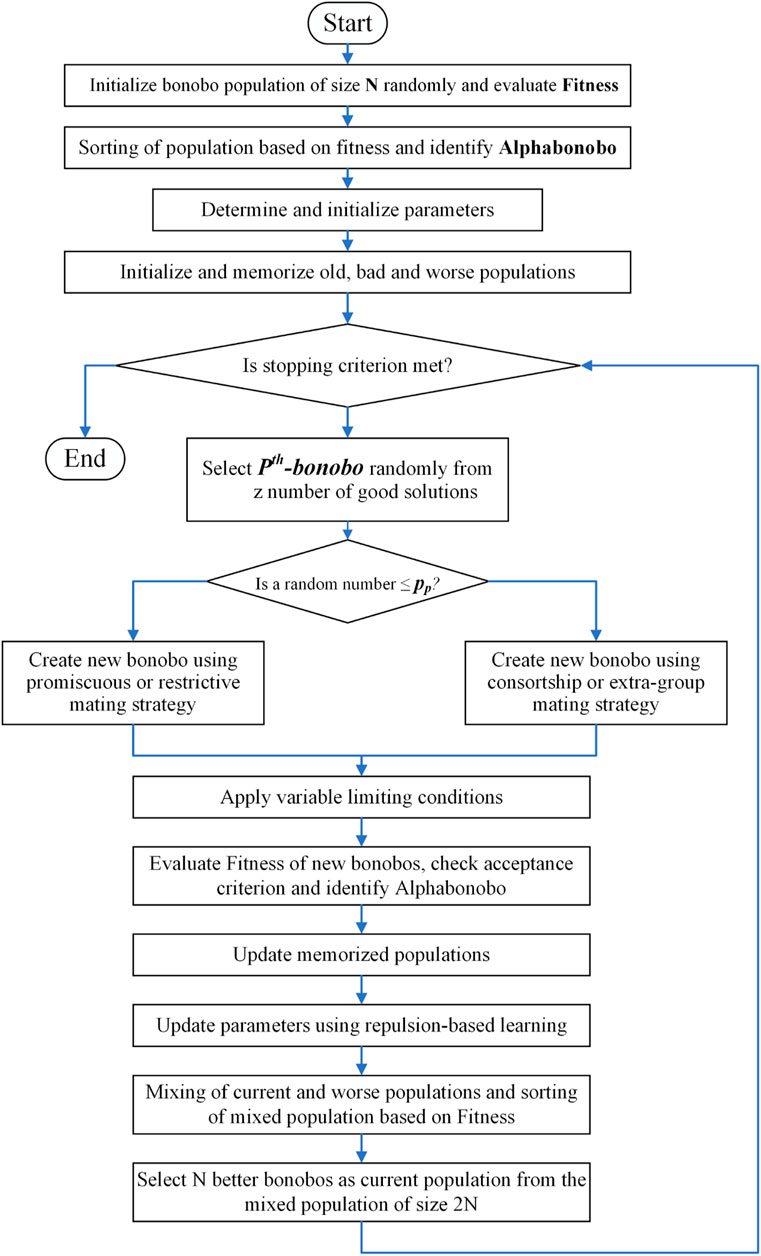
FIGURE 11. Flowchart of the proposed Self-adaptive Bonobo Optimizer (SaBO).
5 Simulation results and discussion
This section presents the performance of the proposed controller for different cases, such as solar irradiance, temperature variation, and load fluctuation using SaBO and other competitive controllers.
5.1 Case (1): variation of solar irradiance
In this scenario, the load is maintained constant at 500 W, at the same time the PV system employs a changing solar radiation profile. The particular profile adheres to the same trend as real solar radiation by being low at the start of the day and climbing to 200 (W/m2) before a substantial increase in the middle of the day to 800 (W/m2). Then it is followed by a significant dip to 500 (W/m2) before sunset as shown in Figure 12.
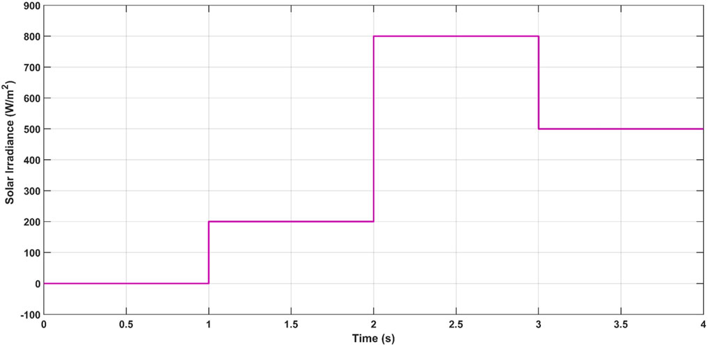
FIGURE 12. Solar irradiance variation.
5.1.1 Performance evaluation of the SaBO compared to other optimization algorithms
In order to assess the reliability, effectiveness, and validity of the SaBO, a range of Optimization Algorithms are employed. The proposed model employs Chimp Optimization Algorithm (ChOA), Gradient-Based Optimizer (GBO), and Wild Horse Optimizer (WHO) for optimization, based on 30 populations and 100 iterations. These techniques could be applied to tune the parameters of the proposed (FOPI-PI) controller using MATLAB/Simulink 2022b software. Table 2 illustrates the various parameters of the abovementioned optimization algorithms in a comprehensive and detailed manner. The fitness function is calculated based on the integral square error method (ISE). It measures the cumulative squared error between the setpoint and the actual signal of a system over a given period.
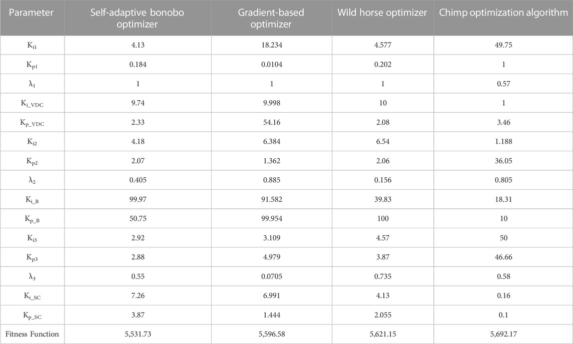
TABLE 2. Parameters of the proposed (FOPI-PI) controller with different Optimization Algorithms.
Figure 13A shows the optimization convergence curves for the GBO, ChOA, WHO, and SaBO methods so that their convergence rates can be compared and understood. The optimization technique (SaBO) proposed in this study succeeded in mastering the list of the four selected algorithms.

FIGURE 13. (A) Convergence rates of ChOA, GBO, WHO and SaBO algorithms, and (B) The PLoad response with the proposed (FOPI-PI) controller combined with different optimizers.
Moreover, a comprehensive analysis of the load power response is carried out in order to assess and contrast the efficacy of the selected optimization approaches. The SaBo optimization method has demonstrated superior performance in comparison to other approaches. For instance, at 2 s, the nearest overshot (GBO) is more than twice the value of the (SaBO). The transient response is also ameliorated with SaBO over other optimization techniques as illustrated in Figure 13B.
Figure 3 The Response of Pload of the proposed (FOPI-PI) controller with different optimization techniquesTechniques.
5.1.2 Implementation of the proposed optimizer (SaBO) with the proposed (FOPI-PI) controller
In this part, the proposed optimizer (SaBO) is incorporated with the proposed controller (FOPI-PI) and applied into the model to analyze the effectiveness, steadiness, and robustness of the proposed system (The optimizer and the controller). Figure 14 exhibits the power response of PV, battery, and the load of the proposed system. During the initial second, the load is fully supplied with the battery as the PV is off. Between the time interval of 1-2 s, it can be shown that the solar irradiance curve indicates a rise so the solar power reaches around 200 W, while the battery power reaches around 300 W. This increase is necessary to fulfill the power need of 500 W. During the third second, the battery is recharged due to the excess of the PV power over the load.
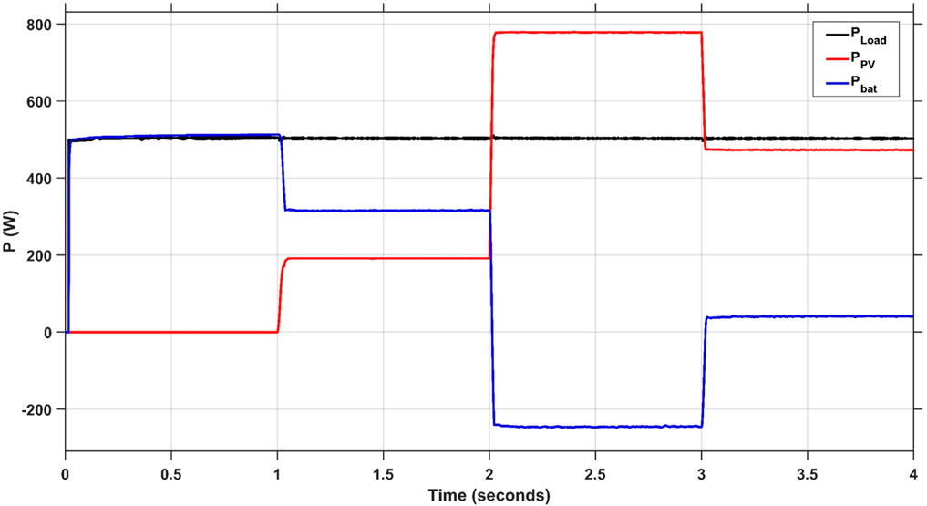
FIGURE 14. Responses of Ppv, Pload and, PBat of the proposed (FOPI-PI) Controller with Variable Solar Irradiance.
5.1.3 Comprehensive comparison between the proposed controller (FOPI-PI) and other controllers using SaBO optimizer
To investigate the strength and durability level of the proposed system (the controller and the optimization technique), a detailed comparison is conducted with different controllers including PI (P et al., 2020; Guentri et al., 2021) and FOPI. Using the model, each controller with SaBO optimizer has been simulated using MATLAB/Simulink 2022b. Figure 15 displays the voltage of the DC bus with the different controllers PI, FOPI, and FOPI-PI.
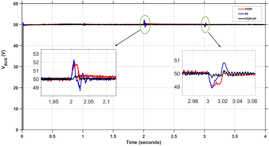
FIGURE 15. Response of Vbus with different controllers.
Table 3 demonstrates the results of each controller transient response including the Maximum overshoot, the transient time, and the steady state error of the system. The response seen at the 2-s mark serves as a distinct illustration of the claimed advantage of the suggested (FOPI-PI) approach in every aspect of comparison.
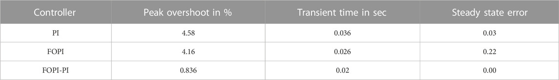
TABLE 3. Summary of transient response specifications for each controller.
The comprehensive comparison can be obtained by inclusive results that are attained through the ESS including the power response of the load, the Photovoltaic system, the battery, and the supercapacitor with variations in solar irradiance. Consequently, it is clearly noticeable that the proposed controller overcomes the other controllers in transient response specifications for the power of the load and the solar system as indicated in Figures 16A, B.
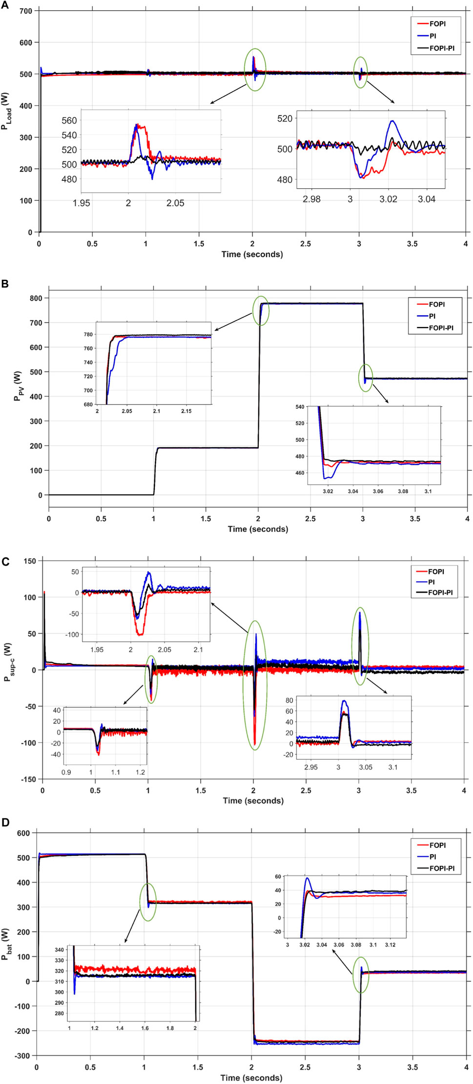
FIGURE 16. Responses of (A) Pload, (B) Ppv, (C) PSup-C, and (D) Pbat of different controllers under solar irradiance variation.
The productivity and effectiveness of the hybrid EES is supported by the results presented in Figures 16C, D. The results demonstrate the harmony between the battery and supercapacitor to provide the load power in case of power shortage from the PV system. The proposed PMS regulates the process of coordination between the battery and supercapacitor by enhancing the response of the hybrid electric ESS during charging or release of power to stabilize the power of the load. For instance, at 2 s, the supercapacitor quickly releases a significant amount of power while simultaneously switching the battery’s mode from draining to charging in order to lessen the load on the battery. To give a clear example of that process, at 3 s, the battery switches from the storage process into the release power process according to the PMS to maintain the load power. At the same time, the supercapacitor provides a power spike in order to maintain the battery power at an appropriate level. It is evident that the proposed (FOPI-PI) controller performance surpasses other mentioned controllers like PI (Guentri et al., 2021) and FOPI to sustain the system’s stability and reliability. For example, at time 1 s, the maximum undershot of the power of the Sup-C is reduced to about 50 W for the proposed FOPI-PI compared to about 55 W and 95 W for PI and FOPI, respectively.
5.2 Case (2): load power variation
The primary objective of the second simulation scenario is to determine and verify the effectiveness of the system’s suggested control approach across various loading circumstances. The power of the solar panel is fixed at 800 W and the variation of the load power is shown in Figure 17.
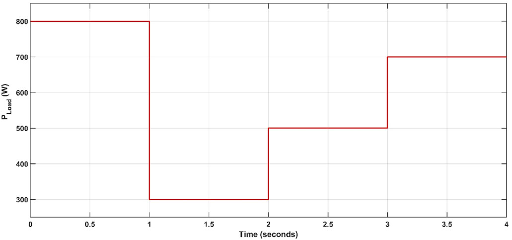
FIGURE 17. Variable load power.
5.2.1 Implementation of the (SaBO) with the proposed (FOPI-PI) controller
Figure 18 demonstrates the variation of the load, the response of the PMS, and the proposed control strategy to accommodate this variation. The battery runs in charging mode to saves the excess power because the power demanded by the load is less than the power developed by the solar system.
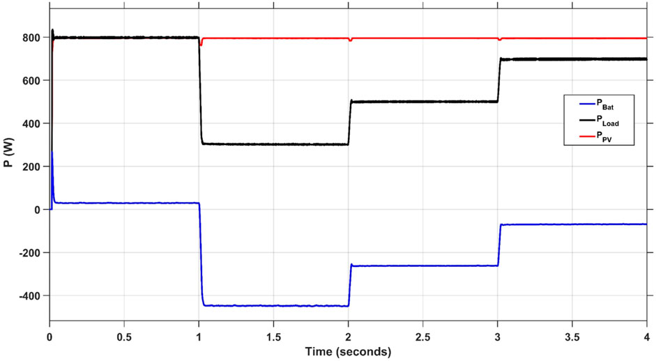
FIGURE 18. Responses of Ppv, Pload and, PBat of the proposed (FOPI-PI) Controller with Variable Load Power.
5.2.2 Comprehensive comparison between the proposed controller (FOPI-PI) and other controllers using the (SaBO)
Numerous controllers including PI (Guentri et al., 2021), FOPI, and FOPI-PI are integrated with the discussed model to test the effectiveness and stability of the proposed controller (FOPI-PI) with the SaBO optimization technique. Figures 19A, B show the load and PV response with the selected control schemes. The proposed control strategy presents a significantly enhanced performance regarding the qualities of transient response such as shorter transient time, lower overshoot or undershoot, and better steady state error with a variation of the load power. For example, at the beginning of the operation, the (FOPI-PI) peak overshot in the load power is reduced to about (6.25%) compared to about (7.875%) and (9.375%) for FOPI and PI, respectively.
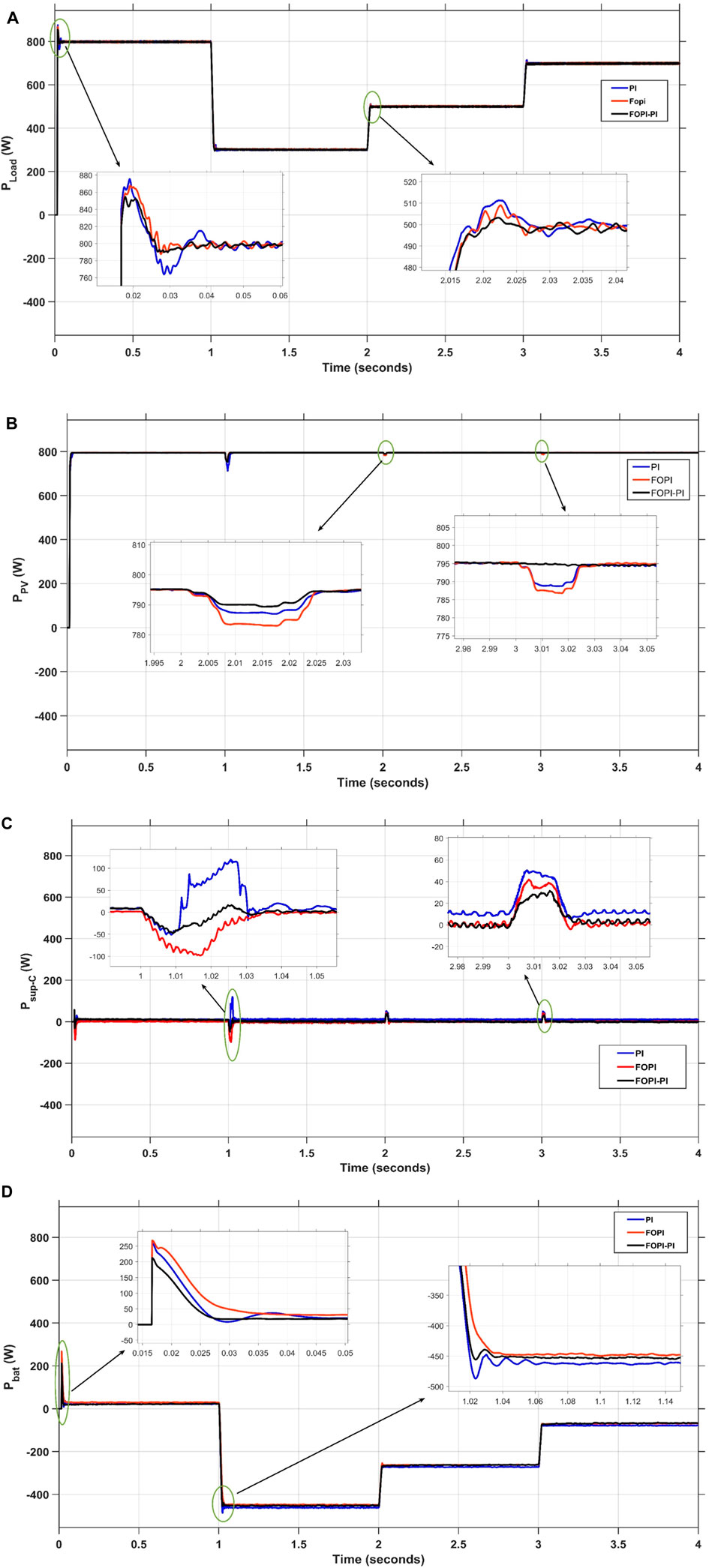
FIGURE 19. Responses of (A) Pload, (B) Ppv, (C) PSup-C, and (D) Pbat of different controllers with variable load power.
By using various controllers to regulate the Sup-C response during the charge and discharge processes, numerous potential advantages of the hybrid EES application can easily be realized. Additionally, the appropriate integration of supercapacitor power at appropriate times will significantly alleviate the strain on the battery, resulting in reduced stress. At t = 1 s, the power load (Pload) experiences a decrease from 800 W to 300 W, prompting the battery to transition into a charging state, reaching around 450 W. At the moment, the Sup-C power is actively engaged in maintaining the load at its designated goal value. The power demand increases from 500 W to 700 W during a time span of 2 s. During this brief period, the battery runs in the discharge state. There is a paucity of power provided by the Sup-C during this period as illustrated in Figures 19C, D. The proposed controller (FOPI-PI) exhibits better performance for the PMS to maintain stability and battery life in the long run than the abovementioned controllers. For instance, at the beginning of the operation, the maximum overshot of the power of the battery is reduced to about 200 W for the proposed FOPI-PI, compared to about 252 W and 255 W for the PI and FOPI, respectively.
5.3 Case (3): temperature variation
In this scenario, the load is maintained constant at 500 W, and at the same time, the PV system employs a changing temperature profile. Figure 20 illustrates the variation in the temperature of the solar panels, which causes a variation in the output power of the PV system. Hence, the output power of the battery also changes to recover the load demand, and the participation of the Sup-C is also needed in times of transient.
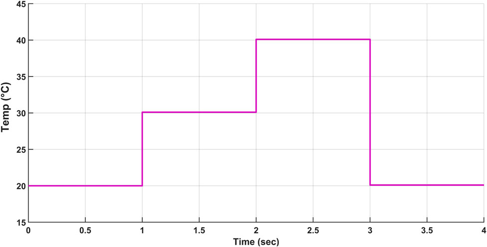
FIGURE 20. Variable temperature profile of the solar system.
5.3.1 Implementation of the (SaBO) with the proposed (FOPI-PI) controller
Figure 21 illustrates the changing output power of the PV system according to the variation in the atmospheric temperature. The effective performance of the PMS system is demonstrated by the cooperation between the battery and the Sup-C to supply the power demanded by the load. For example, from 2 to 3 s, the battery is in discharging mode, and output power is developed to accommodate the required power.
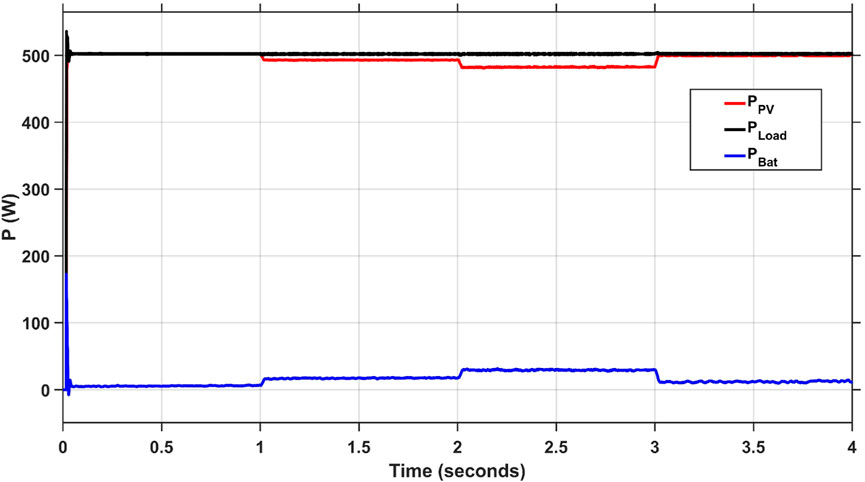
FIGURE 21. Responses of Ppv, Pload and, PBat of the proposed (FOPI-PI) Controller with Temperature Variation.
5.3.2 Comprehensive comparison between the proposed controller (FOPI-PI) and other controllers using the (SaBO)
As shown in Figure 22A, the proposed FOPI-PI controller beats the other controllers (PI) and (FOPI) in terms of transient response and stability. For example, at t = 3 s, the FOPI-PI exposed the least overshot of the PV power (about 0.7%) from PI (about 1%) and FOPI (about 1.2%). Additionally, the steady state error and the settling time are also improved by the proposed controller. Enhancing these specifications is reflected in the performance of the hybrid EES, as shown in Figures 22B, C. At the instant of 1, the stress on the battery is reduced by about (10%) of the FOPI-PI, less than (22.5%) and (27.5%) of the PI and FOPI, respectively. Due to the FOPI-PI controller’s greater performance, the battery’s lifespan is extended.
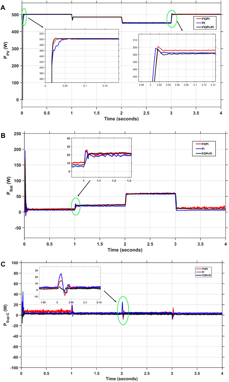
FIGURE 22. Responses of (A) Ppv, (B) PBat, and (C) PSup-C of different controllers with temperature variation.
6 Conclusion
This study introduces an innovative control technique to regulate the power flow between the solar system and the hybrid ESS. The proposed approach separates the low- and high-frequency components of the power and employs the battery’s error current to manage the Sup-C, distinguishing it from traditional techniques. The low frequency power component is regulated by the battery storage system, while the Sup-C takes responsibility for the high frequency component. Furthermore, the proposed cascaded regulator comprises a First Order Plus Integral (FOPI) controller and a traditional Proportional-Integral (PI) controller, which exhibit many substantial advantages. The proposed (FOPI-PI) controller has a vital role in enhancing the transient response, including the settling time, overshoot/undershoot, and transient duration. As a result, the DC bus voltage is maintained constant during load and solar variation to reduce the stress on the battery and increase its lifespan. In order to enhance the robustness of our studies, we employ a novel optimization approach known as SaBO to finely adjust the parameters of the controller. The effectiveness of the incorporated system between the controller and the optimizer has obviously improved the performance of the system. Compared to the other (PI) and (FOPI) controllers, The proposed controller shows great superiority in most cases and aspects of comparison. Subsequently, the transient and dynamic response specifications of the proposed system have been substantially enhanced, as shown in the wealth and extensive results throughout the research.
Data availability statement
The raw data supporting the conclusion of this article will be made available by the authors, without undue reservation.
Author contributions
AK: Conceptualization, Investigation, Writing–original draft. HK: Supervision, Writing–original draft, Validation. KA: Resources, Software, Supervision, Writing–review and editing. MR: Software, Writing–original draft. HE: Supervision, Writing–review and editing. YG: Investigation, Writing–review and editing. AY: Funding acquisition, Writing–review and editing.
Funding
The author(s) declare that no financial support was received for the research, authorship, and/or publication of this article.
Conflict of interest
The authors declare that the research was conducted in the absence of any commercial or financial relationships that could be construed as a potential conflict of interest.
Publisher’s note
All claims expressed in this article are solely those of the authors and do not necessarily represent those of their affiliated organizations, or those of the publisher, the editors and the reviewers. Any product that may be evaluated in this article, or claim that may be made by its manufacturer, is not guaranteed or endorsed by the publisher.
References
Abdelghany, R. Y., Kamel, S., Sultan, H. M., Khorasy, A., Elsayed, S. K., and Ahmed, M. (2021). Development of an improved bonobo optimizer and its application for solar cell parameter estimation. Sustainability 13 (7), 3863. doi:10.3390/su13073863
Abdullah, M. A., et al. (2013). “Control of a bidirectional converter to interface ultracapacitor with renewable energy sources,” in 2013 IEEE International Conference on Industrial Technology (ICIT), Cape Town, South Africa, February, 2013.
Aidoud, M., Feraga, C. E., Bechouat, M., Sedraoui, M., and Kahla, S. (2019). Development of photovoltaic cell models using fundamental modeling approaches. Energy Procedia 162, 263–274. doi:10.1016/j.egypro.2019.04.028
Alam, M. S., Al-Ismail, F. S., Rahman, S. M., Shafiullah, M., and Hossain, M. A. (2023). Planning and protection of DC microgrid: a critical review on recent developments. Eng. Sci. Technol. Int. J. 41, 101404. doi:10.1016/j.jestch.2023.101404
Alramlawi, M., Gabash, A., Mohagheghi, E., and Li, P. (2018). Optimal operation of hybrid PV-battery system considering grid scheduled blackouts and battery lifetime. Sol. Energy 161, 125–137. doi:10.1016/j.solener.2017.12.022
Al-Saadi, M., Al-Greer, M., and Short, M. (2021). Strategies for controlling microgrid networks with Energy Storage Systems: a review. Energies 14 (21), 7234. doi:10.3390/en14217234
Altbawi, S. M. A., Mokhtar, A. S. B., Khalid, S. B. A., Husain, N., Yahya, A., Haider, S. A., et al. (2023). Optimal control of a single-stage modular PV-Grid-Driven system using a gradient optimization algorithm. Energies 16 (3), 1492. doi:10.3390/en16031492
Bhagiya, R. D., and Patel, R. M. (2019). “PWM based double loop PI control of a bidirectional DC-DC converter in a standalone PV/battery DC power system,” in 2019 IEEE 16th India Council International Conference (INDICON), Rajkot, India, December 2019.
Boumediene, S., Nasri, A., Hamza, T., Hicham, C., Kayisli, K., and Garg, H. (2023). Fuzzy logic-based Energy Management System (EMS) of hybrid power sources: battery/Super capacitor for electric scooter supply. J. Eng. Res., doi:10.1016/j.jer.2023.07.008
Chen, Y. (2022). Research on collaborative innovation of key common technologies in new energy vehicle industry based on digital twin technology. Energy Rep. 8, 15399–15407. doi:10.1016/j.egyr.2022.11.120
Cherukuri, S. K., Kumar, B. P., Kaniganti, K. R., Muthubalaji, S., Devadasu, G., Babu, T. S., et al. (2022). A novel array configuration technique for improving the power output of the partial shaded photovoltaic system. IEEE Access 10, 15056–15067. doi:10.1109/access.2022.3148065
Chong, L. W., Wong, Y. W., Rajkumar, R. K., and Isa, D. (2017). Modelling and simulation of standalone PV systems with battery-supercapacitor hybrid energy storage system for a rural household. Energy Procedia 107, 232–236. doi:10.1016/j.egypro.2016.12.135
Chong, L. W., Wong, Y. W., Rajkumar, R. K., and Isa, D. (2018). An adaptive learning control strategy for standalone PV system with battery-supercapacitor hybrid energy storage system. J. Power Sources 394, 35–49. doi:10.1016/j.jpowsour.2018.05.041
Das, A. K., and Pratihar, D. K. (2019). “A new bonobo optimizer (BO) for real-parameter optimization,” in 2019 IEEE Region 10 Symposium (TENSYMP), Kolkata, India, June, 2019.
Deželak, K., Bracinik, P., Sredenšek, K., and Seme, S. (2021). Proportional-integral controllers performance of a grid-connected solar PV system with particle Swarm optimization and ziegler–nichols tuning method. Energies 14 (9), 2516. doi:10.3390/en14092516
Emara, D., Ezzat, M., Abdelaziz, A. Y., Mahmoud, K., Lehtonen, M., and Darwish, M. M. F. (2021). Novel control strategy for enhancing microgrid operation connected to photovoltaic generation and energy storage systems. Electronics 10 (11), 1261. doi:10.3390/electronics10111261
Farh, H. M. H., Al-Shamma’a, A. A., Al-Shaalan, A. M., Alkuhayli, A., Noman, A. M., and Kandil, T. (2022). Technical and economic evaluation for off-grid hybrid renewable energy system using novel bonobo optimizer. Sustainability 14 (3), 1533. doi:10.3390/su14031533
Gorji, S. A., Sahebi, H. G., Ektesabi, M., and Rad, A. B. (2019). Topologies and control schemes of bidirectional DC–DC power converters: an overview. IEEE Access 7, 117997–118019. doi:10.1109/access.2019.2937239
Gu, Q., Li, S., Gong, W., Ning, B., Hu, C., and Liao, Z. (2023). L-SHADE with parameter decomposition for photovoltaic modules parameter identification under different temperature and irradiance. Appl. Soft Comput. 143, 110386. doi:10.1016/j.asoc.2023.110386
Guentri, H., Allaoui, T., Mekki, M., and Denai, M. (2021). Power management and control of a photovoltaic system with hybrid battery-supercapacitor energy storage based on heuristics methods. J. Energy Storage 39, 102578. doi:10.1016/j.est.2021.102578
Gugulothu, R., Nagu, B., and Pullaguram, D. (2023b). Energy management strategy for standalone DC microgrid system with photovoltaic/fuel cell/battery storage. J. Energy Storage 57, 106274. doi:10.1016/j.est.2022.106274
Gugulothu, R., Nagu, B., Pullaguram, D., and Babu, B. C. (2023a). Optimal coordinated energy management strategy for standalone solar photovoltaic system with hybrid energy storage. J. Energy Storage 67, 107628. doi:10.1016/j.est.2023.107628
Hacini, I., Lalouni, S., Idjdarene, K., and Berabez, K. (2023). Energy management of a photovoltaic system with hybrid energy storage battery-super capacitor. J. Ren. Energies, 65–74. doi:10.54966/jreen.v1i1.1099
Humada, A. M., Aaref, A. M., Hamada, H. M., Sulaiman, M. H., Amin, N., and Mekhilef, S. (2018). Modeling and characterization of a grid-connected photovoltaic system under tropical climate conditions. Renew. Sustain. Energy Rev. 82, 2094–2105. doi:10.1016/j.rser.2017.08.053
Humada, A. M., Darweesh, S. Y., Mohammed, K. G., Kamil, M., Mohammed, S. F., Kasim, N. K., et al. (2020). Modeling of PV system and parameter extraction based on experimental data: review and investigation. Sol. Energy 199, 742–760. doi:10.1016/j.solener.2020.02.068
Jing, W., Lai, C. H., Wong, W. S., and Wong, M. D. (2018a). A comprehensive study of battery-supercapacitor hybrid energy storage system for standalone PV power system in rural electrification. Appl. Energy 224, 340–356. doi:10.1016/j.apenergy.2018.04.106
Jing, W., Lai, C. H., Wong, W. S., and Wong, M. D. (2018b). A comprehensive study of battery-supercapacitor hybrid energy storage system for standalone PV power system in rural electrification. Appl. Energy 224, 340–356. doi:10.1016/j.apenergy.2018.04.106
Kim, H.-J., Krishna, T., Zeb, K., Rajangam, V., Gopi, C. V. V. M., Sambasivam, S., et al. (2020). A comprehensive review of Li-ion battery materials and their recycling techniques. Electronics 9 (7), 1161. doi:10.3390/electronics9071161
Kim, Y., Raghunathan, V., and Raghunathan, A. (2017). Design and management of battery-supercapacitor hybrid electrical energy storage systems for regulation services. IEEE Trans. Multi-Scale Comput. Syst. 3 (1), 12–24. doi:10.1109/tmscs.2016.2627543
Kollimalla, S. K., Mishra, M. K., and Narasamma, N. L. (2014). Design and analysis of novel control strategy for battery and supercapacitor storage system. IEEE Trans. Sustain. Energy 5 (4), 1137–1144. doi:10.1109/tste.2014.2336896
Koohi-Fayegh, S., and Rosen, M. A. (2020). A review of energy storage types, applications and recent developments. J. Energy Storage 27, 101047. doi:10.1016/j.est.2019.101047
Kumar, M., and Kumar, A. (2017). An efficient parameters extraction technique of photovoltaic models for performance assessment. Sol. Energy 158, 192–206. doi:10.1016/j.solener.2017.09.046
Kumar Kollimalla, S., Mishra, M., and Narasamma, N. (2014). Design and analysis of novel control strategy for battery and supercapacitor storage system. Sustain. Energy, IEEE Trans.5, 1137–1144. doi:10.1109/tste.2014.2336896
Laldin, O., Moshirvaziri, M., and Trescases, O. (2013). Predictive algorithm for optimizing power flow in hybrid ultracapacitor/battery storage systems for light electric vehicles. IEEE Trans. Power Electron. 28 (8), 3882–3895. doi:10.1109/tpel.2012.2226474
Liao, Q., Li, S., Xi, F., Tong, Z., Chen, X., Wan, X., et al. (2023). High-performance silicon carbon anodes based on value-added recycling strategy of end-of-life photovoltaic modules. Energy 281, 128345. doi:10.1016/j.energy.2023.128345
Liu, Z., Wu, Y., and Feng, J. (2023). Competition between battery switching and charging in electric vehicle: considering anticipated regret. Environ. Dev. Sustain., doi:10.1007/s10668-023-03592-4
Mendalek, N., and Al-Haddad, K. (2017). “Photovoltaic system modeling and simulation,” in 2017 IEEE International Conference on Industrial Technology (ICIT), Toronto, ON, Canada, March 2017.
Min, C., Pan, Y., Dai, W., Kawsar, I., Li, Z., and Wang, G. (2023). Trajectory optimization of an electric vehicle with minimum energy consumption using inverse dynamics model and servo constraints. Mech. Mach. Theory 181, 105185. doi:10.1016/j.mechmachtheory.2022.105185
Nacer, B., Kerdoun, D., Djellad, A., Chiheb, S., and Dekhane, A. (2022). Optimization of fractional order PI controller by PSO algorithm applied to a grid- connected photovoltaic system. J. Eur. des Systèmes Automatisés 55, 427–438. doi:10.18280/jesa.550401
Ongaro, F., Saggini, S., and Mattavelli, P. (2012). Li-ion battery-supercapacitor hybrid storage system for a long lifetime, photovoltaic-based wireless sensor network. IEEE Trans. Power Electron. 27 (9), 3944–3952. doi:10.1109/tpel.2012.2189022
Park, S.-J., Shin, J. H., Park, J. H., and Jeon, H. J. (2014). Dynamic analysis and controller design for standalone operation of photovoltaic power conditioners with energy storage. J. Electr. Eng. Technol. 9, 2004–2012. doi:10.5370/jeet.2014.9.6.2004
Prathikantham, B., and Somlal, D. J. (2023). Harnessing probabilistic neural networks and horse herd optimization for efficient energy management in islanded microgrid operation. https://ssrn.com/abstract=4462840.
Punna, S., and Manthati, U. B. (2020). Optimum design and analysis of a dynamic energy management scheme for HESS in renewable power generation applications. SN Appl. Sci. 2 (3), 495. doi:10.1007/s42452-020-2313-3
Raghavendra, K. V. G., Vinoth, R., Zeb, K., Muralee Gopi, C. V., Sambasivam, S., Kummara, M. R., et al. (2020a). An intuitive review of supercapacitors with recent progress and novel device applications. J. Energy Storage 31, 101652. doi:10.1016/j.est.2020.101652
Raghavendra, K. V. G., Zeb, K., Muthusamy, A., Krishna, T. N. V., Kumar, S. V. S. V. P., Kim, D. H., et al. (2020b). A comprehensive review of DC–DC converter topologies and modulation strategies with recent advances in solar photovoltaic systems. Electronics 9 (1), 31. doi:10.3390/electronics9010031
Ram Babu, N., and Chandra Saikia, L. (2019). Automatic generation control of a solar thermal and dish-stirling solar thermal system integrated multi-area system incorporating accurate HVDC link model using crow search algorithm optimised FOPI Minus FODF controller. IET Renew. Power Gener. 13 (12), 2221–2231. doi:10.1049/iet-rpg.2018.6089
Şahin, M. E., and Blaabjerg, F. (2020). A hybrid PV-battery/supercapacitor system and a basic active power control proposal in MATLAB/Simulink. Electron. (Basel) 9 (1), 129. doi:10.3390/electronics9010129
Shao, B., Xiao, Q., Xiong, L., Wang, L., Yang, Y., Chen, Z., et al. (2023). Power coupling analysis and improved decoupling control for the VSC connected to a weak AC grid. Int. J. Electr. Power & Energy Syst. 145, 108645. doi:10.1016/j.ijepes.2022.108645
Song, J., Mingotti, A., Zhang, J., Peretto, L., and Wen, H. (2022). Accurate damping factor and frequency estimation for damped real-valued sinusoidal signals. IEEE Trans. Instrum. Meas. 71, 1–4. doi:10.1109/TIM.2022.3220300
Thakkar, R. (2021). Electrical equivalent circuit models of lithium-ion battery. https://www.intechopen.com/chapters/78501.
Uloom, N., Mansur, T. M. N. T., Ali, R., Baharudin, N. H., and Abdullah, A. M. (2022). A comparative study of hybrid energy storage system using battery and supercapacitor for stand-alone solar PV system. J. Phys. Conf. Ser. 2312, 012075. doi:10.1088/1742-6596/2312/1/012075
Xiao, Y., Zhang, Y., Kaku, I., Kang, R., and Pan, X. (2021). Electric vehicle routing problem: a systematic review and a new comprehensive model with nonlinear energy recharging and consumption. Renew. Sustain. Energy Rev. 151, 111567. doi:10.1016/j.rser.2021.111567
Yang, Y., Bremner, S., Menictas, C., and Kay, M. (2019). A mixed receding horizon control strategy for battery energy storage system scheduling in a hybrid PV and wind power plant with different forecast techniques. Energies 12 (12), 2326. doi:10.3390/en12122326
Zaouche, F., Rekioua, D., Gaubert, J. P., and Mokrani, Z. (2017). Supervision and control strategy for photovoltaic generators with battery storage. Int. J. Hydrogen Energy 42 (30), 19536–19555. doi:10.1016/j.ijhydene.2017.06.107
Zeraati, M., Golshan, M. E. H., and Guerrero, J. M. (2018). Distributed control of battery energy storage systems for voltage regulation in distribution networks with high PV penetration. IEEE Trans. Smart Grid 9 (4), 3582–3593. doi:10.1109/tsg.2016.2636217
Zhang, R., Xia, B., Li, B., Cao, L., Lai, Y., Zheng, W., et al. (2018). State of the art of lithium-ion battery SOC estimation for electrical vehicles. Energies 11 (7), 1820. doi:10.3390/en11071820
Zhang, X., Wang, Y., Yuan, X., Shen, Y., Lu, Z., and Wang, Z. (2022). Adaptive dynamic surface control with disturbance observers for battery/supercapacitor-based hybrid energy sources in electric vehicles. IEEE Trans. Transp. Electrif., 1. doi:10.1109/tte.2022.3194034
Keywords: photovoltaic, energy management, energy storage, enhanced control, FOPI-PI, SaBO, optimization
Citation: Khairalla AG, Kotb H, AboRas KM, Ragab M, ElRefaie HB, Ghadi YY and Yousef A (2023) Enhanced control strategy and energy management for a photovoltaic system with hybrid energy storage based on self-adaptive bonobo optimization. Front. Energy Res. 11:1283348. doi: 10.3389/fenrg.2023.1283348
Received: 25 August 2023; Accepted: 31 October 2023;
Published: 20 November 2023.
Edited by:
Fanglin Chen, University of South Carolina, United StatesReviewed by:
Rajeev Kumar, KIET Group of Institutions, IndiaImane Hammou Ou Ali, Mohammed V University, Morocco
Salem Al-Ameri, Curtin University Sarawak, Malaysia
Copyright © 2023 Khairalla, Kotb, AboRas, Ragab, ElRefaie, Ghadi and Yousef. This is an open-access article distributed under the terms of the Creative Commons Attribution License (CC BY). The use, distribution or reproduction in other forums is permitted, provided the original author(s) and the copyright owner(s) are credited and that the original publication in this journal is cited, in accordance with accepted academic practice. No use, distribution or reproduction is permitted which does not comply with these terms.
*Correspondence: Hossam Kotb, aG9zc2FtLmtvdGJAYWxleHUuZWR1LmVn; Amr Yousef, YW1yLnlvdXNlZkBhbGV4dS5lZHUuZWc=