 Gangui Yan
 Yupeng Wang
 Cheng Yang2
- 1Key Laboratory of Modern Power System Simulation and Control and Renewable Energy Technology, Ministry of Education (Northeast Electric Power University), Jilin, China
- 2School of Electrical Engineering, Northeast Electric Power University, Jilin, China
Faced with the problem of sub-synchronous oscillation (SSO) caused by the interaction between permanent magnetic synchronous generator (PMSG)-based wind farms and weak AC grids, we construct a transient energy function model that follows the structure of a PMSG. The transient energy composition of a PMSG is analyzed, and the dissipation energy expression that can intuitively reflect the development trend of SSO is derived, reflecting the damping level of a grid-connected wind power system. Furthermore, in response to the problem of mutual coupling between the control links of the PMSG during the SSO process, which hinders oscillation characteristic assessment, a method based on oscillation energy is proposed to analyze the oscillation characteristics. Considering the dynamic changes in the output of the phase-locked loop during sub-synchronous oscillation, the transient energy dominated by various control links is derived, and the effects of the phase-locked loop, current inner loop, and voltage outer loop on transient energy and oscillation characteristics are analyzed. The simulation verifies the effectiveness of the analysis of the transient energy model.
1 Introduction
With the rapid development of new energy represented by wind power, permanent magnet synchronous generators (PMSGs) have been widely used because of their high efficiency and low failure rate. A PMSG employs the power electronic converter as the interface for the power grid, which makes its power generation dynamic characteristics disparate from a traditional synchronous generator. When the converter interacts with the power grid, it can induce resonance or oscillation issues that potentially trigger unit tripping, cause equipment damage, and compromise the safe and stable operation of the power grid (Yuan et al., 2016; Zhou et al., 2018; Xie et al., 2021). In Xinjiang’s Hami region of China, sub-synchronous oscillation (SSO) frequently occurs since 2015 among wind turbine generator clusters, manifesting at frequencies of 20–40 Hz. The sub-synchronous power flows into the power grid with multiple voltage levels of 35, 110, 220, 500, and 750 kV. Furthermore, it even excites torsional vibration of the turbine generators, resulting in tripping of a thermal power unit steam turbine 300 km away and sudden power drops in HVDC transmission systems (Chen et al., 2017a; Li et al., 2017).
Several techniques have been currently employed for analyzing SSO in wind power grid-connected systems, including eigenvalue analysis, complex torque coefficient analysis, impedance analysis, and time-domain simulation, and henceforth, certain results are obtained. Some references use the eigenvalue analysis to study sub-synchronous oscillation, which investigates the system’s dynamic response by solving the eigenvalue of a linearized model for small disturbances (Wu et al., 2016; Chen et al., 2017b). This method can yield insights into the oscillation mode, damping characteristics, participation factor, and sensitivity. However, it can only be used for dynamic characteristic analysis of isolated modes. Some studies apply the complex torque coefficient analysis method to determine the risk of SSO in the system under torsional vibration frequency (Fan and Miao, 2012; Xie et al., 2016). This method involves the scanning and numerical analysis of the equivalent elastic coefficient and damping coefficient. However, it is only suitable for analyzing single-input single-output systems and cannot study complex systems with multiple variable interactions. Some studies use the impedance analysis to establish positive- and negative-sequence impedance models in the abc stationary coordinate system and frequency-domain impedance models in the dq synchronous rotating coordinate system (Dong et al., 2015; Gao et al., 2015). This is a recently globally adopted theoretical method to determine the stability of the system by establishing the small-signal frequency-domain impedance model for power electronic devices and using the (generalized) Nyquist criterion, though it is difficult to analyze the coupling effect between the control links. The time-domain simulation analysis method, as applied in the work of Xie et al. (2016), involves solving the differential equations governing the system’s dynamic characteristics through numerical integration to obtain its time-domain response curve. Although this method can capture the system’s nonlinear behavior, it may not offer adequate information for analyzing the mechanism characteristics of SSO.
SSO in power systems occurs when there is an energy exchange between the oscillating units and the system at a frequency that is lower than the synchronous frequency, which is manifested as power oscillation. Recently, low-frequency oscillations and SSO based on the transient energy method have been studied (Min and Chen, 2007; Chen et al., 2013a; Li et al., 2013a; Chen et al., 2013b). A method for constructing the transient energy function of a power system based on Kirchhoff’s current law was proposed by Min and Chen (2007), where the transient energy function for an induction motor model is derived. Some references propose the concept of energy flow and quantitatively deduce the correlation between the real part of eigenvalue and energy dissipation (Chen et al., 2013a; Chen et al., 2013b). Furthermore, the transient energy is also applied to the identification of oscillation source units (Yu et al., 2010; Li et al., 2013a; Li et al., 2013b) and the classification of low-frequency oscillation types (Mi et al., 2018). In the work of Chen et al. (2016), the transient energy flow method has been expanded to analyze SSO, and an expression for the transient energy during SSO is proposed. The source of sub-synchronous forced oscillation in a single-machine infinite bus system with a steam turbine generator unit has been successfully identified using this method, thus demonstrating its suitability for studying SSO. The above energy methods are mostly traditional synchronous generators, with little involvement in the direct drive wind turbines, and the impact of different time scale control links of PMSGs are not discussed.
We have analyzed the SSO of a PMSG by employing the transient energy flow method, and the contributions of different time scale control links to the SSO process have been examined. On the grounds of the relevant mathematical model, the transient energy flow calculation formula applicable to a PMSG is derived in Section 3. In Section 4, the transient energy properties of different control links are analyzed. The simulations are given in Section 5, whereas the conclusions and prospects of future studies are presented in Section 6.
2 Model construction of the PMSG
2.1 PMSG model
The machine-side converter of a PMSG is decoupled from the grid, and the time scale of wind speed change is far greater than the time scale of converter control. The influence of the grid-side converter (GSC) of a PMSG should be emphatically considered while analyzing SSO in grid-connected wind power systems (Xie et al., 2013; Xie et al., 2016). Figure 1 illustrates the configuration of PMSG GSC connected to the grid.
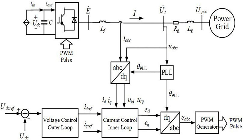
FIGURE 1. Configuration of the PMSG’s GSC connected to the grid.
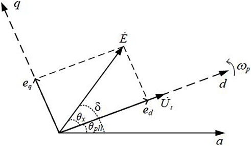
FIGURE 2. Spatial position and phase relationship of the coordinate system.
The GSC of a PMSG includes a DC capacitor and an AC inductor, which are two energy storage components to realize energy exchange with the grid. To maintain the stability of the state variable of the DC capacitor and AC inductor, DC voltage control and AC current control are designed for the GSC (Wang et al., 2022).
The GSC utilizes the phase-locked loop (PLL) to sense the phase of point of interconnection voltage
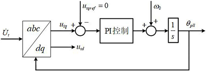
FIGURE 3. Structure of the PLL.
2.2 Multiple time scale characteristics of the PMSG
Owing to the different energy storage capacities of the DC capacitor and AC inductor, the bandwidths of control loops designed according to their state variable are also different. When disturbances occur in the power grid, both the DC capacitor voltage and AC inductance current of the converter change and drive each controller to act. Since the bandwidths of both the DC voltage and AC current controllers differ, the speed and sequence of their response to grid disturbances are also different; i.e., the PMSG control system shows the characteristics of sequential action.
Owing to the sequential action of the controller, the response process of the PMSG to different time scale disturbances is different; i.e., the PMSG exhibits multiple time scale dynamic response characteristics to the power grid. According to the characteristics of energy storage elements and the response speed of their corresponding controllers, Yuan et al. (2016) roughly divided the multi-scale control dynamics of the grid-connected converter into an AC current control scale (about 0.01s) and a DC voltage control scale (about 0.1 s). Generally, the current inner loop control bandwidth in the new energy systems is around 100 Hz, whereas the control bandwidths for the DC voltage loop and terminal voltage loop are designed to be approximately 1/10 of the current inner loop bandwidth (about 10 Hz). Therefore, the dynamics of the PMSG can be divided into different categories according to the time scale, as shown in Figure 4.
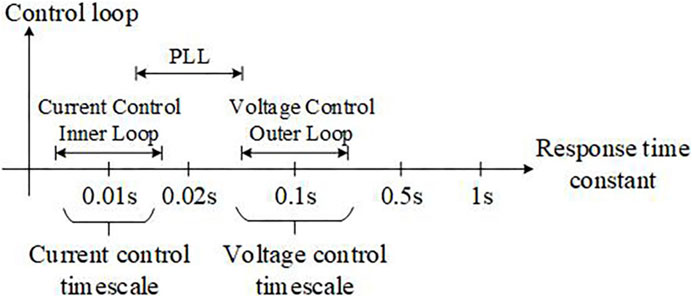
FIGURE 4. Dynamic time scale division of inverter control.
3 Construction of the transient energy function of the PMSG under sub-synchronous frequency
3.1 Node current equation-based transient energy modeling
The essence of oscillation is the accumulation and consumption of disturbance energy between devices. The energy function construction is based on the pure mathematical definition, but the potential energy and dissipated energy contained in the energy function have the same expression as the energy in the real physical process. In the work of Moon et al. (1999), a method has been introduced to derive the system’s transient energy function from the nodal current equations. The transient energy of the system can be obtained by integrating the branch circuit and node information.
where Y denotes the admittance matrix of the system,
We expand Eq. (1) as
where
Equation (2) is consistent with the transient energy function obtained by the first integral method in the power system structure-preserving model (Min and Chen, 2007). Therefore, this method can be employed to analyze the transient energy of the system, and it only requires the information of voltage and current or the information of active power, reactive power, and voltage. Thus, the construction process of the energy function is simple.
In Eq. (2),
where the instantaneous value of the voltage or current is represented as
The transient energy of the PMSG in the dq-axis coordinate system is given as
According to Figure 2, the phase angle of the internal voltage
including
where
3.2 Relationship between sub-synchronous transient energy and electric power of the PMSG
By measuring the power, voltage, and current information of the PMSG, the transient energy and its variation trend of the PMSG can be calculated.
The transient energy of the electrical device obtained through integration cannot be distinguished between potential and kinetic energy. The transient energy of a component consists of two parts. One is a conservative term that is independent of the path, corresponding to the periodic variables, which reflects the periodic change of the transient energy of the electrical device, i.e., kinetic and potential energy over time. The other part is a non-conservative term related to the path, corresponding to the non-periodic variables, which reflects the transient energy consumed by the electrical device, which corresponds to damping. This part of energy is defined as the dissipated energy.
The integration-based approach for obtaining the transient energy of an electrical device cannot differentiate between potential energy and kinetic energy, which is not conducive to analyzing the characteristics of the electrical device. Dissipated energy corresponds to damping in a physical sense. When SSO occurs, the change in dissipated energy determines the damping level of SSO, which is the main basis for analyzing the SSO. In actual calculations, each variable can be represented by its deviation from the steady-state value.
Assuming that there is a symmetrical sub-synchronous sinusoidal disturbance current in the three-phase current output by the GSC of the PMSG, the phase current and voltage can be described as
where
To obtain the PMSG’s transient energy, we first convert the voltage and current values of the PMSG from the static abc coordinate system to the rotating dq-axis coordinate system. Considering the PLL response, the voltage and current converted to the rotating dq-axis coordinate system are as follows:
The dissipated energy is the integral of the non-periodic component in the transient energy expression. We calculate the derivatives
Substituting Eqs (8), (9) into the
Therefore, the dissipated energy at the GSC of the PMSG is given as
Equation (12) illustrates the relationship between the transient energy of the GSC of the PMSG and the actual electrical power in the SSO, i.e., the dissipated energy rate in the SSO is proportional to the sub-synchronous power of the PMSG, thus reflecting the damping behavior of the PMSG. Its magnitude depends on the sub-synchronous voltage and current amplitudes, whereas its sign depends on the phase difference of the sub-synchronous voltage and current. When WDE>0, the PMSG continuously generates the dissipated energy during SSO, which exhibits negative damping characteristics for the oscillation. The transient energy flowing from the PMSG into the power grid continuously increases, thus inducing the instability of oscillation divergence. When WDE<0, the PMSG absorbs the dissipated energy in the process of SSO and shows positive damping characteristics for the oscillation. The transient energy of the PMSG flowing from the PMSG into the power grid gradually decreases, and the oscillation finally converges. When WDE = 0, the PMSG neither generates nor absorbs the dissipated energy, and the system oscillates with equal amplitude under ideal conditions.
4 Analysis of transient energy properties of the PMSG
During the process of sub-synchronous oscillation, the interdependence of each control link of the GSC complicates the analysis of oscillation characteristics. Here, the dynamic effects of the phase-locked loop, current inner loop, and DC voltage outer loop control are considered, and the influence of different time scale control links on transient energy and oscillation characteristics is studied.
4.1 Influence of the dynamic PLL process
According to Eq. (6), calculating the transient energy expression of the PMSG requires obtaining the phase angle δ of the internal voltage of the GSC. According to Figure 2,
where
While SSO occurs, the PLL phase angle is not equal to the steady-state voltage phase angle at the measuring point. This induces a misalignment between the dq-axis coordinate system in the control system and that of the power grid, and the included angle is the variation of the phase-locked angle
The transformation relationship between the voltage or current in the dq-axis coordinate system of the control system and the voltage or current in the dq-axis coordinate system of the power grid is
where A =
4.2 Influence of each control link of the GSC on transient energy
Simultaneous Eqs 6, 13 can give
Since
WTE2 consists of two parts. The first part is the transient energy
To calculate WTE1, it is necessary to obtain the current
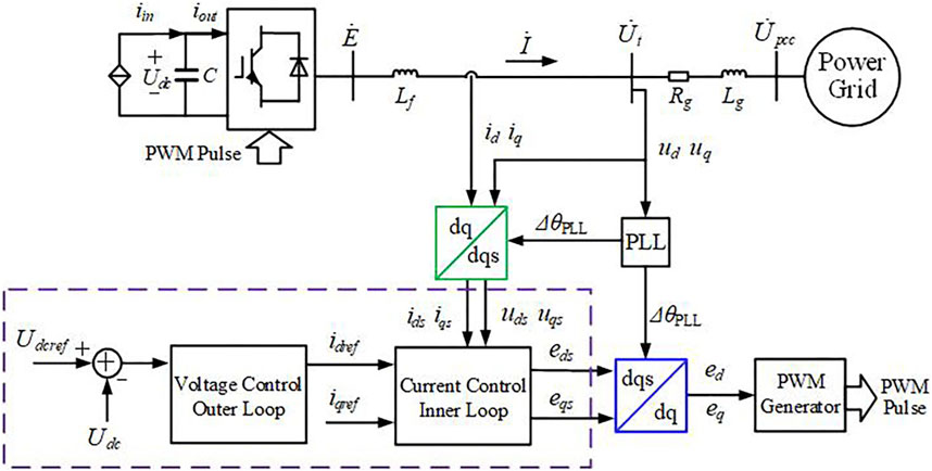
FIGURE 5. Equivalent control system diagram of the GSC of the PMSG.
In the dqs-axis coordinate system of the control system, which is obtained from the current inner loop control equation,
where the proportional and integral coefficients of the current inner loop PI controller are given by
Simultaneously, Eqs (15), (17) give the expression of the internal voltage of the GSC as
Since
Then,
According to Eq. (20), the differential value of d/q-axis internal voltage of the GSC is related to the differential value of d/q-axis terminal voltage and current derived from the measurement terminal, besides being affected by the filter reactance
In engineering, the control bandwidth of the current loop is usually about twice that of the PLL and 10 times that of the voltage outer loop control (Yuan et al., 2017). Therefore, while calculating the differentiation of the related terms coupled with the current loop control, it can be considered that the output values
Furthermore, calculating the differential of the relevant terms coupled with the PLL control, it is considered that
It is assumed that the current loop and PLL control have achieved steady state when calculating the differential of the voltage outer loop control output, which yields the expression
where
From the simultaneous Eqs 6, 21–23, we obtain
Here,
The other items are the transient energy items that are directly affected by the control link. The second item of the expression is the transient energy dominated by the current loop control. The third item is the transient energy controlled by the PLL, and the fourth item is the transient energy controlled by the DC voltage outer loop.
The third item is the transient energy dominated by the PLL control, whose positive and negative values mainly depend on the PLL link, though the magnitude of the transient energy is still affected by the current loop. The GSC of the PMSG uses a decoupling control technique for the active and reactive power, which causes the d-axis current to govern the output of active power and the q-axis current to govern the output of reactive power:
By combining Eq. 16 and removing the transient energy components
Therefore, the influence of the controls of the PLL, current loop, and DC voltage outer loop of the GSC on the transient energy characteristics of the PMSG is obtained. In the case of the transient energy WC contributed by the control link being positive, the transient energy input from the PMSG to the system continuously increases during the transient process, which exacerbates the SSO divergence. If the oscillation energy WC contributed by the control link is negative, the transient energy input from the PMSG to the system gradually converges during the transient process, which suppresses the development of SSO.
5 Verification
In PSCAD/EMTDC, a simulation example system is built to demonstrate the integration of a direct drive wind farm with a weak AC power grid. The wind farm’s overall generating capacity is 900 MW (1.5 MW*600), and the terminal voltage of the PMSG is 0.69 kV. Furthermore, the power grid is connected after the voltage rise (0.69 kV/220 kV). We set different operating conditions to measure the transient energy and dissipated energy of the PMSG and check the reliability of the PMSG’s transient energy model. Parameters of the GSC of the PMSG are shown in Table 1.
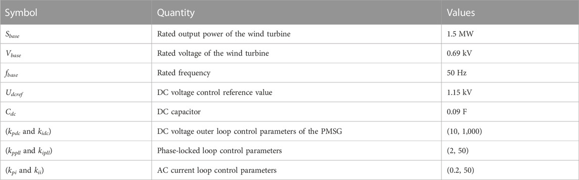
TABLE 1. Parameters of the GSC of the PMSG.
5.1 Understanding the SSO characteristics of the grid-connected wind power system through transient energy
We set different oscillation types, viz., SSO divergence and SSO convergence, to ascertain the accuracy and feasibility of the transient energy model of the PMSG.
(1) Sub-synchronous divergence oscillation occurs in the grid-connected wind power system
At an operational condition of 4 m/s, the AC grid’s equivalent impedance changes, where the grid strength is reduced from SCR = 3.4 to 1.5 at t = 5s, thus causing divergent SSO in the example system. The transient and dissipated energy of the PMSG are measured.
The upper half of Figure 6 indicates that the grid-connected wind power system undergoes divergent SSO, and after reaching the power limit, the PMSG’s output power exhibits equal amplitude SSO. By calculating the transient and dissipated energy of the port of the PMSG, the lower half of Figure 6 illustrates that the dissipated energy of the PMSG increases as the power divergence progresses. After the power reaches the limit, the dissipated energy increases uniformly. Therefore, when SSO occurs in the grid-connected wind power system, the total dissipated energy of the PMSG increases continuously, and the PMSG provides energy for the SSO, thus showing a negative damping characteristic.
(2) Sub-synchronous convergence oscillation occurs in the grid-connected wind power system
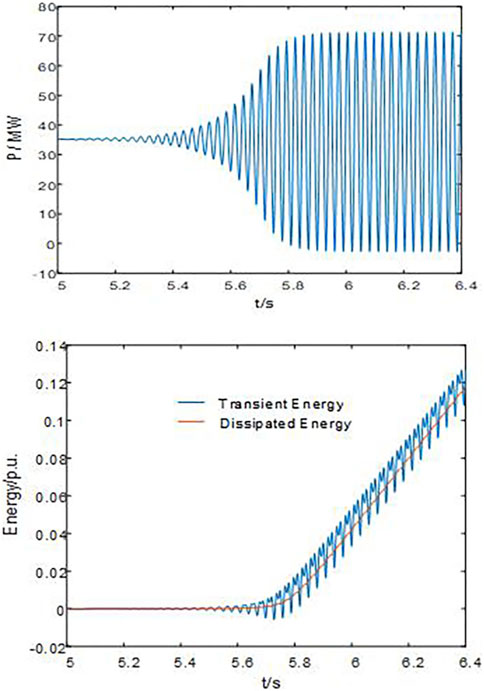
FIGURE 6. Power waveform, transient energy, and dissipated energy waveform of the PMSG under the divergent SSO in the system.
At an operational condition of 7 m/s, the AC grid’s equivalent impedance changes, where the grid strength is reduced from SCR = 3.4 to 1.5 at t = 5s, thus causing convergent SSO in the example system. The transient and dissipated energy of the PMSG are measured.
The upper half of Figure 7 shows that the grid-connected wind power system undergoes SSO, and the output power of the PMSG oscillates and converges. By calculating the dissipated energy of the port of the PMSG, the lower half of Figure 7 illustrates that the dissipated energy of the PMSG is negative; hence, the PMSG absorbs the energy of SSO, which results in a positive damping effect on the SSO, which is consistent with the result of gradual convergence of power oscillation, as shown in the upper half of Figure 7.
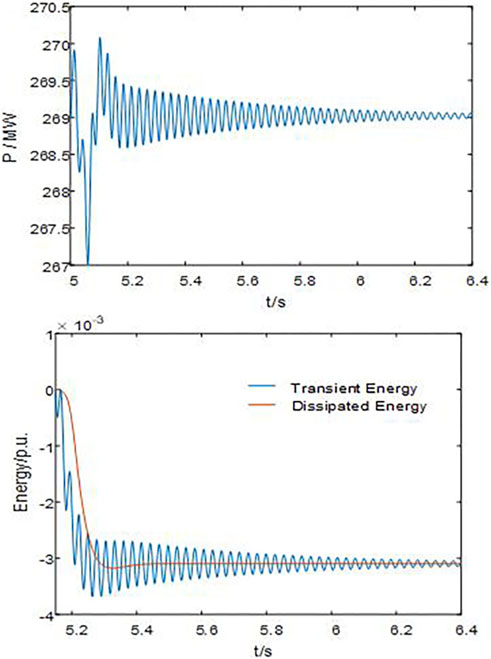
FIGURE 7. Power waveform, transient energy, and dissipated energy waveform of the PMSG for the sub-synchronous convergence oscillation in the system.
As mentioned above, the dissipated energy of the PMSG can be employed to gauge the damping level of the grid-connected wind power system besides understanding the sub-synchronous oscillation characteristics.
5.2 Understanding the impact of each PMSG under different operating conditions on the SSO characteristics of the system via transient energy analysis
The direct drive wind farm connected to the weak power grid faces SSO risk. Since there are differences in the operating conditions of each sub-wind farm, their influence on the SSO characteristics can also vary. Here, it is assumed that the operating conditions of the PMSGs in each sub-wind farm are identical.
We divide the 600 PMSGs in the example system into two sub-wind farms, each with 300 PMSGs. The operating condition of sub-wind farm 1 is 4 m/s, and the operating condition of sub-wind farm 2 is 7 m/s. The transient energy and dissipated energy of the PMSGs of two sub-wind farms are measured.
According to Figure 8, the direct drive wind farm with two sub-wind farms with different operating conditions undergoes SSO. The output power of both the sub-wind farms oscillates and diverges, and the role of the two sub-wind farms in the process of SSO cannot be analyzed through the power oscillation curve.
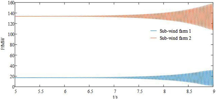
FIGURE 8. Power waveform of sub-wind farm 1 and sub-wind farm 2.
According to Figure 9, the PMSG of sub-wind farm 1 generates dissipated energy, whereas the PMSG of sub-wind farm 2 absorbs dissipated energy. The two sub-wind farms play different roles in the process of SSO. The PMSG in sub-wind farm 1 generates more dissipated energy than the PMSG in sub-wind farm 2 can absorb. This leads to a net positive dissipated energy and a continuous increase in the transient energy that ultimately results in system instability.
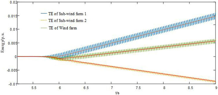
FIGURE 9. Transient energy curve of sub-wind farm 1 and sub-wind farm 2.
Therefore, the corresponding manifestation mode of SSO is power oscillation, which primarily depends on the energy exchange between the wind farm and the power grid.
5.3 Influence of each control link of the GSC of the PMSG on transient energy
The GSC parameters of the PMSG are provided in Table 1, including the current inner loop’s proportional and integral coefficients
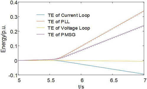
FIGURE 10. Transient energy of each control link of the PMSG.
According to Figure 10, the transient energy provided by the current loop of the GSC of the PMSG is negative, thus exhibiting the characteristic of reducing the transient energy of the PMSG, which is beneficial for system stability. The transient energy provided by the PLL control is positive, which shows the characteristics of generating the transient energy and having a negative damping effect on the SSO. Furthermore, its energy size exceeds the negative transient energy provided by the current loop, which results in the total transient energy exceeding zero, the transient energy output of the PMSG increasing continuously, and the grid-connected wind power system losing stability. The DC voltage outer loop control provides negligible transient energy; hence, it has negligible impact on the transient energy of the PMSG.
(1) The impact of the proportional coefficient of the current inner loop on transient energy
We change the proportion coefficient (
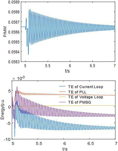
FIGURE 11. Power waveform of the PMSG and transient energy of each link of the PMSG when
According to Figure 11 and Figure 6, the simulation example system undergoes sub-synchronous convergence oscillation under the same disturbance. Increasing the proportion coefficient is beneficial for system stability. According to Figure 11, the transient energy provided by the current loop of the GSC exceeds the transient energy provided by the PLL control in this case, thus resulting in the total transient energy being below zero and the power system ultimately remaining stable.
(2) The influence of the integral coefficient of the current inner loop on transient energy
We change the integral coefficient (
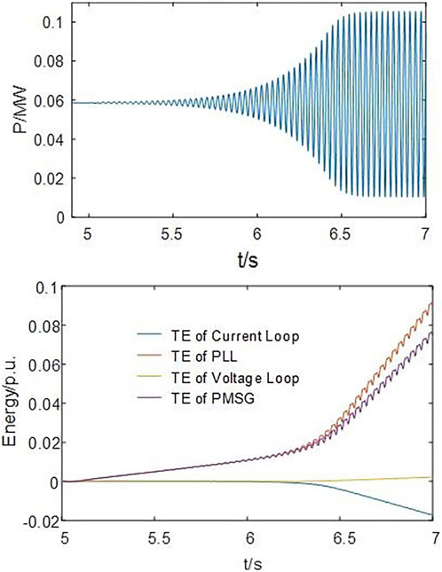
FIGURE 12. Power waveform of the PMSG and transient energy of each link of the PMSG when
Comparing Figure 12 and Figure 6, the simulation example system still undergoes sub-synchronous divergence oscillation under the same disturbance, though the divergence speed slows down. Decreasing the integral coefficient is beneficial for system stability. According to Figure 12 and Figure 10, although the total transient energy exceeds zero after decreasing the integral coefficient, the absolute value of transient energy provided by the current loop and PLL decreases, and the total oscillation energy decreases, besides the damping level of the power system being enhanced.
Thus, the participation of the PMSG in the SSO is primarily associated with the control of the GSC. The transient energy dominated by each control link of the GSC is derived with the support of simulation results.
In the process of SSO, the transient energy contributed by the PLL is positive, which increases the transient energy of the PMSG and easily leads to oscillation divergence. The transient energy contributed by the current loop is negative, which decreases the transient energy of the PMSG and is beneficial to the oscillation convergence.
Both the order of magnitude of the transient energy contributed by the voltage outer loop and its effect on SSO are negligible.
For the GSC’s current loop parameters of the PMSG, increasing the proportional coefficient and decreasing the integral coefficient can reduce transient energy, which is beneficial for suppressing oscillations.
6 Conclusion
Starting from the physical essence, this article describes the dynamic development process of SSO by employing the transient energy and, based on that, constructs a method for analyzing SSO. Focusing on the coupling effects between control links at different time scales, the transient energy dominated by various control links is derived, and the effects of the PLL, current inner loop, and voltage outer loop on transient energy and oscillation characteristics are analyzed. The results of the simulation demonstrate that the transient energy analysis can provide valuable insights into the SSO characteristics of the grid-connected wind power system, and the impact of each PMSG under different operating conditions on the sub-synchronous oscillation characteristics of the system can be understood. In the control link of the GSC, the transient energy contributed by the PLL and current loop plays a dominant role in the transient energy characteristics, determining the characteristics of SSO.
A striking number of PMSGs are typically present in a direct drive wind farm, and there is mutual influence between PMSGs during the process of SSO. The transient energy characteristic analysis of the PMSG by considering the coupling relationship is the focus of our future work.
Data availability statement
The original contributions presented in the study are included in the article/Supplementary Material; further inquiries can be directed to the corresponding author.
Author contributions
GY: writing–review and editing. YW: writing–original draft and writing–review and editing. CY: writing–review and editing. LY: writing–review and editing.
Funding
The authors declare financial support was received for the research, authorship, and/or publication of this article. This work was supported by the National Natural Science Foundation of China (No. U1866601).
Conflict of interest
The authors declare that the research was conducted in the absence of any commercial or financial relationships that could be construed as a potential conflict of interest.
Publisher’s note
All claims expressed in this article are solely those of the authors and do not necessarily represent those of their affiliated organizations, or those of the publisher, the editors, and the reviewers. Any product that may be evaluated in this article, or claim that may be made by its manufacturer, is not guaranteed or endorsed by the publisher.
References
Chen, G., Li, M., Xu, T., and Liu, M. (2017a). Study on technical bottleneck of new energy development. Proc. Chin. Soc. Electr. Eng. 37 (1), 20–26. doi:10.13334/j.0258-8013.pcsee.161892
Chen, L., Chen, Y., Min, Y., Hu, W., and Zhang, K. (2013b). Low frequency oscillation analysis and oscillation source location based on oscillation energy: Part two method for oscillation source location and case studies. Autom. Electr. Power Syst. 36 (4), 1–5+27. doi:10.3969/j.issn.1000-1026.2012.04.001
Chen, L., Min, Y., and Hu, W. (2013a). Low frequency oscillation analysis and oscillation source location based on oscillation energy: Part one mathematical foundation and energy flow computation. Autom. Electr. Power Syst. 36 (3), 22–27+86. doi:10.3969/j.issn.1000-1026.2012.03.004
Chen, L., Wang, W., Wang, M., Min, Y., Xie, X., and Xu, F. (2016). Disturbance source location of subsynchronous forced oscillation and damping evaluation using transient energy flow. Autom. Electr. Power Syst. 40 (19), 1–8. doi:10.7500/AEPS20160503007
Chen, W., Wang, D., Xie, X., Ma, J., and Bi, T. (2017b). Identification of modeling boundaries for SSR studies in series compensated power networks. IEEE T Power Syst. 32 (6), 4851–4860. doi:10.1109/TPWRS.2017.2669402
Dong, X., Xie, X., Han, Y., and Li, J. (2015). Mechanism study of DFIG-related SSR based on separate stator and rotor torque analysis. Proc. Chin. Soc. Electr. Eng. 35 (19), 4861–4869. doi:10.13334/j.0258-8013.pcsee.2015.19.003
Fan, L., and Miao, Z. (2012). Nyquist-stability-criterion-based SSR explanation for type-3 wind generators. IEEE T Energy Conver 27 (3), 807–809. doi:10.1109/TEC.2012.2193491
Gao, B., Li, R., Yang, D., Song, R., Zhao, S., Liu, J., et al. (2015). Damping characteristics and countermeasures of DFIG subsynchronous oscillation. Electr. Power Autom. Equip. 35 (12), 11–21. doi:10.16081/j.issn.1006-6047.2015.12.002
Li, M., Yu, Z., Xu, T., He, J., Wang, C., Xie, X., et al. (2017). Study of complex oscillation caused by renewable energy integration and its solution. Power Syst. Technol. 41 (4), 1035–1042. doi:10.13335/j.1000-3673.pst.2016.3049
Li, W., Guo, J., Li, Y., Zhou, X., Chen, L., Bu, G., et al. (2013a). Power system oscillation analysis and oscillation source location based on WAMS: Part 1 method of cutset energy. Proc. Chin. Soc. Electr. Eng. 33 (25), 41–46. doi:10.13334/j.0258-8013.pcsee.2013.25.013
Li, W., Li, Y., Zhou, X., Guo, J., Bu, G., Tao, X., et al. (2013b). Power system oscillation analysis and oscillation source location based on WAMS: Part 2 method of torques decomposition. Proc. Chin. Soc. Electr. Eng. 33 (25), 47–53. doi:10.3897/zookeys.326.5970
Mi, X., Wang, J., and Wang, R. (2018). Frequency analysis of low frequency oscillation in multi-machine system based on energy function and incomplete elliptic integral. High. Volt. Engg 44 (1), 321–328. doi:10.13336/j.1003-6520.hve.20171227039
Min, Y., and Chen, L. (2007). A transient energy function for power systems including the induction motor model. Sci. China Ser. E Technol. Sci. 50 (5), 575–584. doi:10.1007/s11431-007-0077-2
Moon, Y. H., Cho, B. H., Lee, Y. H., and Hong, H. S. (1999). “Energy conservation law and its application for the direct energy method of power system stability,” in Proceedings of the Paper presented at IEEE Power Engineering Society. 1999 Winter Meeting, New York, NY, USA, February 1999. doi:10.1109/PESW.1999.747540
Wang, Y., Yan, G., Mu, G., and Yang, C. (2022). Research on aggregation modeling of grid connected VSC under AC current control scale. Proc. Chin. Soc. Electr. Eng. 42 (8), 2900–2909. doi:10.13334/j.0258-8013.pcsee.220294
Wu, M., Xie, L., Cheng, L., and Sun, R. (2016). A study on the impact of wind farm spatial distribution on power system sub-synchronous oscillations. IEEE T Power Syst. 31 (3), 2154–2162. doi:10.1109/TPWRS.2015.2455873
Xie, X., He, J., Mao, H., and Li, H. (2021). New issues and classification of power system stability with high shares of renewables and power electronics. Proc. Chin. Soc. Electr. Eng. 42 (2), 461–474. doi:10.13334/j.0258-8013.pcsee.201405
Xie, X., Liu, H., He, J., Zhang, C., and Qian, Y. (2016). Mechanism and characteristics of subsynchronous oscillation caused by the interaction between full-converter wind turbines and AC systems. Proc. Chin. Soc. Electr. Eng. 36 (9), 2366–2372. doi:10.13334/j.0258-8013.pcsee.2016.09.007
Xie, X., Liu, H., He, J., Zhang, C., and Qiao, Y. (2013). Mechanism and characteristics of subsynchronous oscillation caused by the interaction between full-converter wind turbines and AC systems. Proc. Chin. Soc. Electr. Eng. 36 (9), 2366–2372. doi:10.13334/j.0258-8013.pcsee.2016.09.007
Yang, L., Chen, Y., Zhou, L., Chen, Z., Zhou, X., Wu, W., et al. (2018). Effect of phase locked loop on the small-signal perturbation modeling and stability analysis for three-phase LCL-type grid-connected inverter in weak grid. Proc. Chin. Soc. Electr. Eng. 38 (13), 3792–3804. doi:10.13334/j.0258-8013.pcsee.171652
Yu, Y., Min, Y., Chen, L., and Zhang, Y. (2010). Gains by a space-time-code based signaling scheme for multiple-antenna RFID tags. Autom. Electr. Power Syst. 34 (5), 1–6. doi:10.1109/CCECE.2010.5575154
Yuan, H., Yuan, X., and Hu, J. (2017). Modeling of grid-connected VSCs for power system small-signal stability analysis in DC-link voltage control timescale. IEEE T Power Syst. 32 (5), 3981–3991. doi:10.1109/TPWRS.2017.2653939
Yuan, X., Cheng, S., and Hu, J. (2016). Multi-time scale voltage and power angle dynamics in power electronics dominated large power systems. Proc. Chin. Soc. Electr. Eng. 36 (19), 5145–5154. doi:10.13334/j.0258-8013.pcsee.161247
Keywords: permanent magnet synchronous generator, sub-synchronous oscillation, characteristic analysis, transient energy, dissipation energy
Citation: Yan G, Wang Y, Yang C and Yue L (2023) Analysis of sub-synchronous oscillation characteristics of PMSGs based on transient energy. Front. Energy Res. 11:1294832. doi: 10.3389/fenrg.2023.1294832
Received: 15 September 2023; Accepted: 20 November 2023;
Published: 06 December 2023.
Edited by:
Youbo Liu, Sichuan University, ChinaReviewed by:
Hui Liu, Guangxi University, ChinaBing Sun, Tianjin University, China
Pupu Chao, Dalian University of Technology, China
Wuhui Chen, Taiyuan University of Technology, China
Copyright © 2023 Yan, Wang, Yang and Yue. This is an open-access article distributed under the terms of the Creative Commons Attribution License (CC BY). The use, distribution or reproduction in other forums is permitted, provided the original author(s) and the copyright owner(s) are credited and that the original publication in this journal is cited, in accordance with accepted academic practice. No use, distribution or reproduction is permitted which does not comply with these terms.
*Correspondence: Yupeng Wang, MjAxNzI3NTNAbmVlcHUuZWR1LmNu