 Li Li1
 Jianru Qin
 Qinglei Zhang
- 1State Grid Shaanxi Electric Power Company Ltd., Xian, Shanxi, China
- 2Sichuan Energy Internet Research Institute, Tsinghua University, Chengdu, Sichuan, China
The insufficient system strength in the high-proportion new energy access area has gradually emerged as a crucial factor contributing to the transient overvoltage issue. Therefore, it is imperative to propose a reactive power optimization operation mode that takes into consideration both the power grid strength and system operating voltage of the new energy cluster system. Firstly, the relationship between the evaluation index of power grid strength and the performance of system voltage response is elucidated, while analyzing the influence mechanism of various reactive power compensation devices on the power grid strength of new energy cluster systems. Then, a reactive power operation optimization model is proposed to maximize the strength of the system grid and minimize the voltage deviation. To solve this problem, a hybrid approach combining genetic algorithm and CPLEX solver is employed. Finally, the effectiveness of the proposed method is validated through a typical simulation example.
1 Introduction
The issue of voltage stability has emerged as a prominent concern in ensuring the safety and reliability of large-scale power grids in recent years, necessitating an immediate enhancement of dynamic reactive power reserves. On one hand, the issue of “Strong DC and weak AC” in power grids becomes prominent with the advancement and implementation of DC transmission technology (RAO et al., 2015; LI et al., 2018; RAO et al., 2019). Moreover, due to the dense DC drop point and relatively close electrical distance of the load center at the receiving end, a single AC failure often leads to simultaneous multiple DC commutation failures (LIU et al., 2015; XU et al., 2019). The construction of large-scale new energy bases, primarily wind power and photovoltaic, in remote areas has led to prominent issues such as a weak DC power grid and insufficient short-circuit capacity. Additionally, the decline in dynamic reactive power reserve and voltage stability has become more significant (ZHANG et al., 2011; CHEN et al., 2016). On the contrary, the rapid increase in load on the asynchronous motor at the load center will result in a decline in bus voltage and further depletion of reactive power within the system, ultimately leading to voltage collapse and large-scale power outage incidents. It is imperative to ensure an adequate supply of dynamic reactive power on a large scale to address this insufficiency in voltage support.
The integration of large-scale new energy into the power grid has prompted experts and scholars, both domestic and foreign, to propose the concept of power grid strength as a measure of the interaction between traditional power grids and connected new energy power electronic equipment. This concept is characterized by two dimensions: frequency support strength and voltage support strength (Australian Energy Market Operator, 2020b; Australian Energy Market Operator, 2020a). The voltage support strength refers to the system’s ability to maintain voltage stability during significant disturbances, and it is commonly assessed using the short circuit ratio index (XIN et al., 2020; ZHU et al., 2021; WU et al., 2022). In order to assess the strength of new energy grid-connected systems, scholars have proposed the concept of critical short-circuit ratio (WANG et al., 2019; CAO et al., 2023) as an index for evaluating the short-circuit ratio. The voltage support capability of the system is assessed by comparing the real-time short-circuit ratio with the critical short-circuit ratio. Due to the existence of various short-circuit ratio index construction methods for different Scale of new energy grid connection and new energy access forms (Lin et al., 2022a), there is a challenge in ensuring consistency between the calculation of critical short-circuit ratio index and the boundary value used for system strength assessment (Wu et al., 2018; Lin et al., 2022b; YANG et al., 2023). The short-circuit ratio and critical short-circuit ratio calculation methods proposed in literature (Lin et al., 2022b) can be employed for the evaluation of each new energy station’s short-circuit ratio within the new energy multi-feed system. These methods enable identification of weak links in the new energy cluster system and contribute to formulating strategies for strengthening the weak power grid system. Therefore, this paper primarily adopts these literature-based approaches to assess the strength of the system power grid.
The existing literature on voltage control through reactive power compensation can be categorized into two distinct groups. The first type refers to in situ reactive power compensation (Kirn and Lee, 2005; Abdel-Rahman et al., 2006; Park and Baek, 2012; LIU et al., 2019; Fan et al., 2020; Wen and ZHOU, 2020). The literature (Fan et al., 2020) suggests connecting the fast reactive power compensation device to the heavy-load distribution station and coordinating it with the capacitor bank and on-load regulating transformer. The literature (Wen and ZHOU, 2020) proposed a voltage control technology for distribution stations based on the coordination between SVC and on-load regulator transformers. The literature (Abdel-Rahman et al., 2006) presents a SVC access strategy incorporating two-stage slope regulation and two-stage voltage regulation control. The literature (Park and Baek, 2012) proposes a voltage coordination control method based on local reactive power compensation, which is developed through extensive research on shunt capacitors, reactors, and on-load regulating transformers. The literature (Kirn and Lee, 2005) presents a reactive power compensation approach utilizing artificial neural network. The literature (LIU et al., 2019) presents a centralized/local adaptive reactive voltage coordination control approach for active distribution networks. The limitation of the above method is obvious, the local compensation does not take into account the tidal flow of the power system, and it has little improvement on the economic and stable operation of the power system. The second approach involves coordinating reactive power compensation devices in the power system to achieve system voltage control (FU et al., 2018; NI and LI, 2020; WANG et al., 2020; XIAO et al., 2020; TANG et al., 2021; ZHU and ZHAO, 2021). The literature (XIAO et al., 2020) presents a reactive power optimization model that is based on sensitivity analysis. The characteristics of voltage control in load center SVC were analyzed in reference (WANG et al., 2020). The literature (ZHU and ZHAO, 2021) proposes a voltage control method that utilizes static synchronous compensation and coordinated optimization of on-load regulator transformers for enhanced performance. The literature (TANG et al., 2021) presents a regional voltage control approach that can be applied to the penetration of FACTS devices (NI and LI, 2020). A voltage adaptive coordination control method is proposed in reference (FU et al., 2018). To summarize, the existing studies solely focus on voltage stability as the single objective during stable system operation, neglecting the requirements for system strength in weak grid scenarios of new energy clusters. Hence, this paper aims to enhance the power grid strength of new energy clusters by proposing a multi-type reactive power compensation optimization method that considers constraints related to short-circuit ratios. This approach enables simultaneous consideration of both voltage stability objectives and system power grid strength requirements.
Taking into account the aforementioned considerations, the relationship between the evaluation index of power grid strength and the voltage response performance of the system is examined, and the influence mechanism of various reactive power compensation devices on the power grid strength in a new energy cluster system is analyzed. Subsequently, a model for optimizing reactive power operation is proposed to maximize system grid strength while minimizing voltage deviation. A hybrid strategy combining genetic algorithm and CPLEX solver is employed to solve this problem. Finally, a typical simulation example is presented to validate the effectiveness of the proposed method.
2 Study on the relationship between power grid strength and system voltage response performance
In the power system with high penetration rate of new energy, system strength is a common concern, the system “strong” and “weak” is a relative concept, not simply based on the capacity of the new energy equipment connected to the AC grid to evaluate, that is, can not be simply judged as a new energy grid connected to the small capacity of the system, its grid strength is higher than the new energy grid connected to the large capacity of the power system. The short-circuit ratio is currently widely employed to characterize the system strength of new energy clusters (Lin et al., 2022b), as shown in Eq. 1:
Where,
The above traditional short-circuit ratio indicators have two limitations for the new energy multi-feed system. Firstly, it is challenging to establish a standardized benchmark capacity due to the varying installed capacities of new energy in each network. Secondly, when considering the impact of junction voltage, it is necessary to take into account not only the directly connected new energy but also other new energy feeds. The proposed short-circuit ratio index
Where,
The expression of the relationship between short circuit ratio and junction voltage can be further derived as per the literature derivation (Lin et al., 2022b).
Where,
The short-circuit ratio index, as indicated by formula (3), exhibits an inverse relationship with the voltage change at the junction point. A higher short-circuit ratio corresponds to a smaller voltage change at the junction point, indicating enhanced system anti-disturbance capability and increased system strength.
In order to facilitate the analysis of the coupling mechanism between the short-circuit ratio index and the reactive power at the system node, the short-circuit ratio shown in Eq. 2 is calculated and simplified as follows:
In Eq. 4,
The focus of this paper is primarily on evaluating the operational strength of the short-circuit ratio system, whereby the actual output of new energy at parallel points is utilized for calculating the equivalent short-circuit ratio, rather than relying on the installed capacity of new energy.
3 Influence analysis of multi-type reactive power compensation devices on power grid strength of new energy cluster system
In order to enhance the voltage performance of new energy grid-connected systems and strengthen weak grid systems of new energy clusters, common methods for reactive power compensation include the installation of static var compensators (SVC) and static var generators (SVG), as well as utilizing the reactive power emitted by the new energy equipment itself for reactive power compensation. The various methods of reactive power compensation, however, employ distinct mechanisms to enhance the strength of the system grid. The subsequent section will elucidate the mechanism employed by each method during the calculation process for short-circuit ratio.
The calculation process of the short-circuit ratio index is illustrated in Figure 1. Initially, the admittance matrix of the system is established based on its structure (including lines, transformers, etc.), incorporating the subtransient reactance of conventional units into the admittance matrix while disregarding the impedance of the inverter interface for new energy equipment, then the system impedance matrix is derived by taking the inverse of the admittance matrix. According to the principle of symmetrical short-circuit calculation, the per unit value of node short-circuit current is obtained by taking the reciprocal of the self-impedance of each system node. Consequently, the short-circuit capacity for each node in the system is determined. Finally, formula (4) and 5 are utilized to measure the system strength of each new energy node and obtain their respective short-circuit ratios.
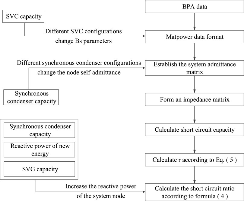
FIGURE 1. The process of short-circuit ratio calculation.
The short-circuit ratio calculation process reveals that the inclusion of various reactive power compensation methods impacts the calculation of each node’s short-circuit ratio, subsequently influencing the determination of new energy output limits for each node and ultimately affecting the absorption capacity of each new energy station. Among them, the input of SVC and synchronous compensator primarily impact the short-circuit capacity of each node in the system by modifying the admittance matrix. However, direct access to tuning the synchronous compensator affects the self-admittance matrix of the access node location. SVC is considered as an electrical admittance matrix parallel to the bus, which explains why synchronous compensator has a better compensation effect compared to SVC. The reactive power of Static Var Generator (SVG) and renewable energy sources mainly increases the reactive power of the system node power supply. Table 1 summarizes the impact mechanism of each reactive power compensation mode on short-circuit ratio calculation.
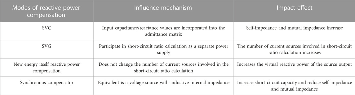
TABLE 1. Influence mechanism of reactive power compensation on new energy consumption.
In order to quantitatively analyze the impact of the aforementioned reactive power compensation methods on the system’s power grid strength, a comparative analysis is conducted using a new energy gathering and transmission terminal system as an example to assess the effectiveness of reactive power compensation methods on KSCR. The calculation results are presented in Table 2, where WT/PV indicates that the reactive power of the new energy station is used to compensate the reactive power. The calculation results demonstrate that the implementation of any of the four reactive power compensation methods can effectively enhance the short-circuit ratio at the grid-connected node of new energy. The increase in KSCR for SVC is the smallest among them, with a growth rate ranging from 1% to 8%, and the majority of which are below 5%. The two modes of SVG compensation and new energy reactive power compensation exhibit a similar magnitude of improvement for KSCR, ranging from 6% to 11%. The addition of the synchronous compensator has a significantly noticeable impact on KSCR, resulting in an evident improvement. The installation of the distributed synchronous compensator at new energy power stations under the gathering station leads to an enhancement level exceeding 40% for KSCR, with the highest improvement reaching 83%. Therefore, the utilization of synchronous compensator for reactive power compensation and enhancement of power grid strength has become a prominent focus within the industry.
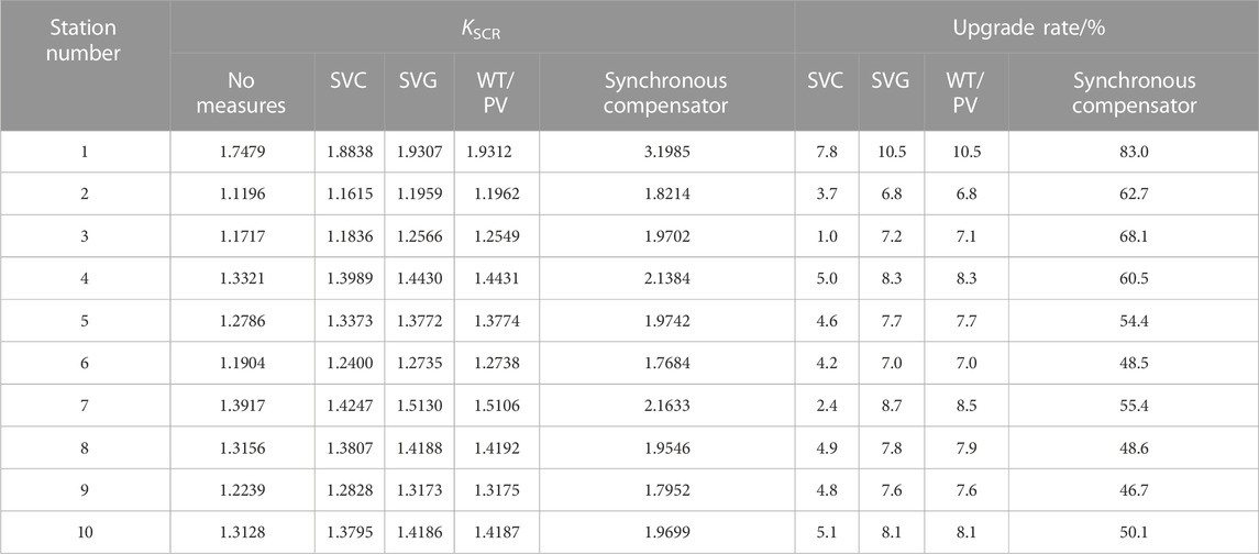
TABLE 2. Comparison of KSCR calculation results of some new energy stations under different reactive power compensation methods.
4 A mathematical model for optimal reactive power operation considering power grid strength and voltage fluctuations
During conventional operations for optimizing reactive power in a power grid, once the placement of each reactive power compensation device is determined, adjustments are made to their outputs (e.g., SVGs and synchronous compensators) in order to comply with system constraints. This ensures economic and secure operation of the grid while achieving minimal voltage deviations at every node. The analysis of the impact of various types of reactive power compensation devices on the power grid strength in the new energy cluster system, as described in Part 2, reveals that adjusting the output of these devices can effectively enhance the short-circuit ratio and overall system strength. Therefore, the paper comprehensively examines the regulatory impact of reactive power compensation devices on system voltage and power grid strength It proposes an optimized operational mode for reactive power optimization that considers both power grid strength requirements and voltage fluctuations.
4.1 Objective function
The objective function is defined as the minimum sum of voltage offsets across all nodes in the system, aiming to address the issue of voltage fluctuation. The specific expression is shown as Eq. 6:
Where, M represents the total number of nodes in the system;
According to the short-circuit ratio calculation formula and the traditional reactive power-voltage adjustment process, the reactive power required by the short-circuit ratio adjustment process of the new energy node can only be matched with the reactive power required by the traditional reactive power-voltage adjustment process when there is a forward shift in system node voltage (i.e., when the voltage of the new energy node exceeds 1pu). The goal of minimizing voltage deviation and maximizing the power grid strength at new energy junction points necessitates the establishment of a deficiency penalty index ΔK when the voltage per unit value exceeds 1 and the short-circuit ratio index is below 2. To achieve this, we establish the following objective function to minimize the deficiency penalty in power grid strength. As shown in Eqs. 7, 8.
Where, N represents the number of grid-connected new energy sources;
In summary, the multi-objective function is shown as Eq. 9:
Where, a and ß are the weight coefficients.
4.2 Constraint function
The control variables for reactive power optimization include the synchronous compensator and SVG reactive power output, while the state variable is represented by the voltage of each node in the system. The establishment of the following operational constraint equation is necessary to ensure the economical and safe operation of the system by maintaining control variables and state variables within a limited range.
(1) Power flow equilibrium equation. The equation constraint in this paper is based on the active and reactive power balance of each node in the system. As shown in Eq. 10.
Where,
(2) Control variable inequality constraints. The reactive power optimization problem addressed in this paper encompasses the output reactive power control variables of SVG and the output reactive power control variables of the synchronous compensator, which must satisfy the following inequality constraints. As shown in Eqs. 11, 12.
Where,
(3) State variable constraints. The state variable in the optimization problem is the node voltage, which must satisfy both an upper bound and a lower bound. As shown in Eq. 13:
Where,
5 Model solving method
The genetic algorithm (GA) is an adaptive global optimization probability search algorithm that simulates the genetic and evolutionary processes of organisms in their natural environment. The variables that need to be solved are encoded into a chromosome for genetic modification, while the objective function corresponding to a set of variable values is transformed into an individual fitness. The initial value is randomly assigned, and after the process of natural selection, individuals that meet the criteria are selected. Genetic operations such as replication, crossover, and mutation are then performed on these individuals to obtain the succeeding generation. The process is iterated until an optimal solution is obtained or the genetic algorithm reaches a predetermined threshold.
When applying genetic algorithms to power system optimization, it is important to recognize that the power flow solution within the system is subject to various constraints. The effectiveness of these solutions is evaluated based on an objective function, whereby those with lower evaluation values are discarded while only those with higher evaluation values have the opportunity to iterate their characteristics into subsequent rounds of solutions. Ultimately, this iterative process aims towards achieving optimization.
5.1 Coding
The genetic algorithm is well-suited for mixed integer optimization, making the coding process between the reactive power optimization problem and chromosome highly convenient. The optimization scheme can be represented by each chromosome, thus this paper employs the real number coding method. The synchronous compensator and SVG output reactive power as control variables. Therefore, the chromosome of the control variable can be represented as Eq. 14:
Where, Ns and Nc represent the total number of SVG and synchronous compensator respectively;
5.2 Solution step
Step 1. Input system network parameters, including transmission lines, transformers, shunt capacitors, sub-transient reactance of synchronous generators, load constant impedance. Then calculate the system admittance matrix Y
Step 2. Utilize the reactive power output of synchronous synchronous compensator and the SVG as control variables, carry out genetic coding, and generate the initial population;
Step 3. Invert the admittance matrix Y to derive the system impedance matrix Z, and extract the self-impedance and mutual impedance of the new energy connection point, SVG installation point, and synchronous synchronous compensator installation point to form a new power supply impedance matrix Znew. The short circuit capacity of the new energy connection point, SVG installation point, and synchronous synchronous compensator installation point is determined based on the power impedance matrix Znew. Then, for each individual of the initial population in step 2, the short-circuit ratio index value under different SVG and synchronous synchronous compensator reactive power output is calculated.
Step 4. Calculate the voltage value of each node for every individual in the initial population from Step 2, considering different reactive power outputs of SVG and synchronous modulation cameras.
Step 5. The objective function value of the multi-type reactive power compensation optimization operation method is calculated, and genetic operations are performed on the population, including selection, crossover, and mutation, to obtain a new population.
Step 6. Determine if the maximum number of iterations has been reached. If so, terminate the calculation and output the result; otherwise, increment the iteration count by one (
The algorithm flow is shown in Figure 2.
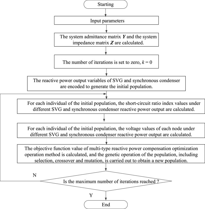
FIGURE 2. Algrithm flow chart.
6 Case study
6.1 Introduction to the case study system
The effectiveness of the proposed method is verified by using the improved IEEE9-node system as an example in this paper, as depicted in Figure 3. On the basis of the original IEEE9-node system, thermal power units with capacities of 100MW, 150 MW and 150 MW are respectively placed on the original generator nodes, and 250 MW wind power, 250 MW wind power and 250 MW PV are respectively placed at nodes 4, 6 and 8. At the same time, 50Mvar synchronous compensator +250Mvar SVG, 200Mvar SVG and 200Mvar SVG are placed at nodes 4, 6 and 8 respectively. This configuration establishes a weak power grid system predominantly driven by new energy sources.
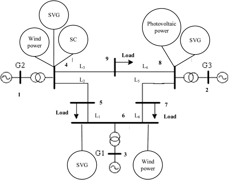
FIGURE 3. Improved IEEE9 node example system.
6.2 The scenario setting of the comparative example
The present study aims to investigate the impact of various reactive power compensation devices on the strength and voltage of the system grid. To achieve this, two different schemes have been devised in this paper:
Scheme 1: The conventional approach to reactive power optimization solely focuses on the objective of minimizing voltage deviation.
Scheme 2: Reactive power optimization (reactive power optimization model proposed in this paper) takes into account both the maximization of new energy grid-connected strength and the minimization of voltage deviation.
6.3 Comparative analysis of daily operating voltage
As depicted in Figure 4, node 4 represents a new energy node that encounters the issue of overvoltage. Considering the limitations imposed by the system power grid’s strength, the voltage deviation between node 4 and node 1 is comparatively smaller when compared to conventional reactive power optimization strategies.
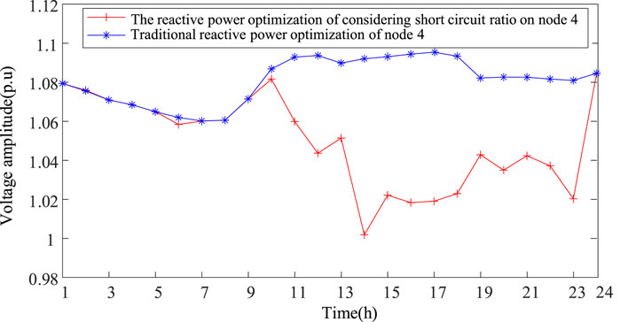
FIGURE 4. The comparison of daily voltage for node 4.
Taking the operating voltage of nodes 7 as an example, it can be observed from Figure 5 that in the absence of a power supply at node 7 within the system, no overvoltage issue arises. However, this observation fails to satisfy the essential conditions of the proposed reactive power optimization model in this paper, which aims to maximize power grid strength. Consequently, compared to the reactive power optimization strategy presented in this study, traditional approaches exhibit smaller voltage deviations and fluctuations.
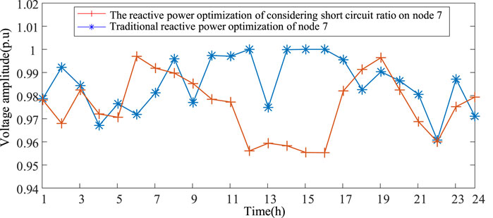
FIGURE 5. The comparison of daily voltage for node 7.
6.4 Comparative analysis of voltage offset
Taking node 8’s voltage deviation as an example, Figure 6 illustrates that the traditional reactive power optimization strategy results in a maximum voltage offset of 0.072 and a minimum voltage offset of 0.0026. However, by incorporating the goal of maximizing power grid strength, the maximum voltage offset is reduced to 0.0639 while achieving a minimum voltage offset of zero. Hence, the proposed reactive power optimization method outperforms the traditional approach.
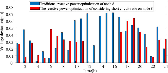
FIGURE 6. The voltage offset of node 8.
6.5 Comparative analysis of short circuit ratio in daily operation
The analysis of Figure 7 reveals that, in consideration of the strength constraints imposed by the system power grid, node 4 exhibits a higher daily operating short-circuit ratio compared to the critical short-circuit ratio 2. However, under the traditional reactive power optimization strategy, there are certain time periods where the operating short-circuit ratio of node 4 falls below the critical value of 2. This discrepancy fails to fully satisfy the strength requirements of the system power grid and hampers large-scale integration of new energy sources.
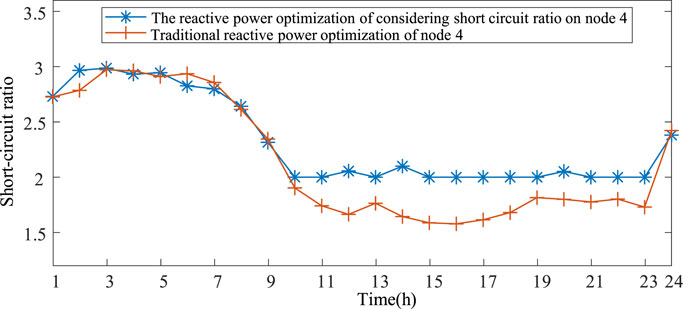
FIGURE 7. The comparison of short-circuit ratio in daily operations for node 4.
6.6 Comparative analysis of daily running reactive power output
The analysis in Figure 8 reveals that nodes 4 and 8 necessitate lesser daily reactive power compensation, considering the strength constraints of the system power grid, compared to the conventional reactive power optimization strategy. This approach effectively reduces the demand for reactive power compensation capability within the system and enhances its dynamic reactive power reserve against significant disturbances.
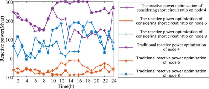
FIGURE 8. Comparison of reactive power output of nodes 4, 6 and 8.
In summary, the proposed optimal operation model of reactive power compensation, considering the constraint of new energy limit grid-connected strength, can simultaneously achieve the objectives of minimizing voltage deviation and maximizing power grid strength under overvoltage conditions.
7 Conclusion
The paper analyzes the influence mechanism of multi-type reactive power compensation devices on the power grid strength of new energy cluster systems, and proposes a reactive power operation optimization model that aims to maximize the power grid strength while minimizing voltage deviation. The specific conclusions are as follows.
(1) The influence of various reactive power compensation methods on short-circuit ratio calculation is analyzed based on the calculation process, and the impact of multi-type reactive power compensation methods on enhancing the power grid strength is quantified.
(2) The calculation results demonstrate that both the reactive power compensation method of the new energy equipment itself and the SVG reactive power compensation method exhibit similar effects in enhancing system power grid strength, surpassing the SVC compensation method. Notably, the installation of synchronous condenser yields the most pronounced effect on improving new energy absorption capacity.
(3) After considering the objective of maximizing the system grid strength, the reactive power compensation required by the new energy interconnection points is reduced compared to that of traditional reactive power optimization strategies. This effectively enhances the dynamic reserve capacity of reactive power in dealing with significant disturbances.
The next research direction of this paper is to establish a comprehensive reactive power resource optimization planning model, encompassing various types of reactive power compensation measures, in order to enhance the new energy consumption capacity of weak power grids while considering economic factors.
Data availability statement
The original contributions presented in the study are included in the article/Supplementary material, further inquiries can be directed to the corresponding author.
Author contributions
LiL: Validation, Writing–review and editing. JQ: Conceptualization, Methodology, Writing–original draft, Writing–review and editing. HH: Data curation, Writing–review and editing. QZ: Investigation, Writing–review and editing. LeL: Investigation, Writing–review and editing.
Funding
The author(s) declare financial support was received for the research, authorship, and/or publication of this article. This study received funding from State Grid Shaanxi Electric Power Co., Ltd. Science and Technology Project, SGSN0000DKJS2313584.
Conflict of interest
Authors LiL, QZ, and LeL were employed by State Grid Shaanxi Electric Power Company Ltd.
The remaining authors declare that the research was conducted in the absence of any commercial or financial relationships that could be construed as a potential conflict of interest.
The handling editor DZ declared a past collaboration with the author JQ.
The authors declare that this study received funding from State Grid Shaanxi Electric Power Co., Ltd. The funder had the following involvement in the study: collection of data.
Publisher’s note
All claims expressed in this article are solely those of the authors and do not necessarily represent those of their affiliated organizations, or those of the publisher, the editors and the reviewers. Any product that may be evaluated in this article, or claim that may be made by its manufacturer, is not guaranteed or endorsed by the publisher.
References
Abdel-Rahman, M. H., Youssef, F. M. H., and Saber, A. A. (2006). New static var compensator control strategy and coordination with under-load tap changer. IEEE Trans. Power Deliv. 21 (3), 1630–1635. doi:10.1109/tpwrd.2005.858814
Cao, W., Qin, H., Lu, J., He, B., Zhuang, K., Li, G., et al. (2023). Orienta-tion and application prospect of virtual synchronous generator in new power system. Automation Electr. Power Syst. 47 (4), 190–207.
Chen, L., Liu, Y., Dai, Y., Min, Y., Zhang, W., Hou, K., et al. (2016). Study on the mechanism of transient voltage stability of new energy source with power electronic interface. Power Syst. Prot. Control 44 (9), 15–21. doi:10.7667/PSPC150481
Fan, X., Wang, T., Rao, Y., Zhang, Y., Ai, Q., Zhou, Y., et al. (2020). Static voltage stability margin evolution based on gradient boosting regression tree. Electr. Meas. & Instrum. 57 (20), 39–45.
Fu, Y., Zhou, X., and Su, X. (2018). Adaptive and coordinated volt/var optimization for unbalanced active distribution networks of multiple voltage levels. Power Syst. Technol. 42 (7), 2136–2147.
Kirn, G. W., and Lee, K. Y. (2005). Coordination control of ULTC transformer and STATCOM based on an artificial neural network. IEEE Trans. Power Syst. 20 (2), 580–586. doi:10.1109/TPWRS.2005.846205
Lin, Y. U., Sun, H., Xu, S., Zhao, B., Zhang, J., Li, Z., et al. (2022a). Overview of strength quantification indexes of power system with power electronic equipment. Proc. CSEE 42 (2), 499–515.
Lin, Y. U., Sun, H., Xu, S., Zhao, B., Zhang, J., Li, Z., et al. (2022b). Short circuit ratio index analysis and critical short circuit ratio calculation of renewable energy grid-connected system. Proc. CSEE 42 (03), 919–929.
Liu, J., Ye, B., Zhang, S., and Li, Q., (2019). Adaptive centralized/local Volt-VAR control in active distribution network. Power Syst. Clean Energy 35 (11), 20–29.
Liu, Z., Zhang, Q., Wang, Y., Dong, C., and Zhou, Q. (2015). Research on reactive compensation strategies for improving stability level of sending-end of 750 kV grid in Northwest China. Proc. CSEE 35 (5), 1015–1022.
Li, Z., Wu, X., Lu, C. A. O., Hou, Y., Li, W., Luo, J., et al. (2018). Emergency control of synchronous condenser to suppress DC continuous commuta tion failure. Automation Electr. Power Syst. 42 (22), 91–97. doi:10.7500/AEPS20170726005
Ni, F., and Li, Z. (2020). Overview of unified power quality conditioner research development. Power Syst. Prot. Control 48 (20), 177–187.
Park, J. H., and Baek, Y. S. (2012). Coordination control of voltage between STATCOM and reactive power compensation devices in steady-state. J. Electr. Eng. Technol. 7 (5), 689–697. doi:10.5370/jeet.2012.7.5.689
Rao, H., Leng, X., Pan, Y., Wei, J., Yuan, Z., Tu, L., et al. (2019). Analysis of the global HVDC power transmission development and the sug gestion of the HVDC export. South. Power Syst. Tech. nology 13 (10), 1–7.
Rao, H., Zhang, D., Zhao, X., and Guo, Q. (2015). Practice and analysis of UHVDC transmission. High. Volt. Eng. 41 (8), 2481–2488. doi:10.13336/j.1003-6520.hve.2015.08.002
Tang, T., Ming, M. A., Ouyang, J., Liang, X., Wang, Y., Li, M., et al. (2021). Reactive power and voltage coordinationcontrol strategy of dfig-based wind farm under wind speed variations. Guang Dong Electr. Power 34 (5), 19–27. doi:10.3969/j.issn.1007-290X.2021.005.003
Wang, S., Pan, X., Yan, J., Li, L., and Wang, Z. (2020). Coordinated control of steady-state voltage for UHVDC/AC power systems with large-scale synchronous condenser integration. Power Syst. Prot. Control 48 (24), 120–127. doi:10.19783/j.cnki.pspc.200060
Wang, Y., Guo, C., and Zhao, C. (2019). A quantita-tive evaluation approach for critical operating SCR of MMC system based on small-signal stability and operating con-straints. Proc. CSEE 39 (10), 2853–2863. doi:10.13334/j.0258-8013.pcsee.180793
Wen, Q. U., and Zhou, H. (2020). Implementation of a new reactive power compensation mode for 10 kV power users. Power Capacitor React. Power Compens. 41 (4), 130–132.
Wu, Di, Li, L. I., Javadi, M., Malyscheff, A. M., Hong, M., and Jiang, J. N. (2018). Assessing impact of renewable energy integration on system strength using site-dependent short circuit ratio. IEEE Trans. Sustain. Energy 9 (3), 1072–1080. doi:10.1109/tste.2017.2764871
Wu, L., Li, Y., Yu, S., Sun, Y., Wang, X., Yang, Y., et al. (2022). Stability analysis of dense wind power area based on short circuit ratio index. Electr. Power Autom. Equip. 42 (08), 72–78.
Xiao, F., Han, M., Tang, X., and Zhang, X. (2020). Voltage stability of weak sending-end system with large-scale grid-connected photovoltaic power plants. Electr. Power 53 (11), 31–39. doi:10.11930/j.issn.1004-9649.202007045
Xin, H., Gan, D., and Ju, P. (2020). Generalized short circuit ratio of power systems with multiple power elec-tronic devices: analysis for various renewable power generations. Proc. CSEE 40 (17), 5516–5526. doi:10.13334/j.0258-8013.pcsee.200827
Xu, G., Fan, S., Luo, C., and Han, W. (2019). Operation characteristic of synchronous condenser and SVC for dynamic re active power compensation of DC converter station. J. North China Electr. Power Univ. Nat. Sci. Edition) 46 (1), 47–53. doi:10.3969/j.ISSN.1007-2691.2019.01.07
Yang, S., Li, B., Zhao, T., Zhao, W., Xu, P., Xie, H., et al. (2023). Tran-sient Angle instability mode and mechanism of distributed synchronous condensers in renewable energy station. Automation Electr. Power Syst. 47 (3), 12–18.
Zhang, F., Li, M., Pan, G., Luo, Z., and Chang, X. (2011). Transient voltage stability study about a regional grid integrated with wind power. Electr. Power 44 (9), 17–21. doi:10.3969/j.issn.1004-9649.2011.09.004
Zhu, J., and Zhao, W. (2021). Voltage control strategy of a UHV AC power grid considering the influence of line power flow fluctuation on bus voltage. Power Syst. Prot. Control 49 (6), 76–82. doi:10.19783/j.cnki.pspc.200567
Keywords: power grid strength, reactive power optimization, voltage control, multiple target, reactive power compensation device
Citation: Li L, Qin J, Hu H, Zhang Q and Luo L (2024) Optimized operational approach for multi-type reactive power compensation to enhance the grid integration strength of new energy clusters. Front. Energy Res. 11:1342770. doi: 10.3389/fenrg.2023.1342770
Received: 22 November 2023; Accepted: 05 December 2023;
Published: 03 January 2024.
Edited by:
Donghui Zhang, Tsinghua University, ChinaCopyright © 2024 Li, Qin, Hu, Zhang and Luo. This is an open-access article distributed under the terms of the Creative Commons Attribution License (CC BY). The use, distribution or reproduction in other forums is permitted, provided the original author(s) and the copyright owner(s) are credited and that the original publication in this journal is cited, in accordance with accepted academic practice. No use, distribution or reproduction is permitted which does not comply with these terms.
*Correspondence: Jianru Qin, UWluanJfTEtAMTI2LmNvbQ==