 Huanle Zhai
 Wei Li
 Jiwei Li1
 Leilei Ji
- 1Aviation Engineering Institute, Jiangsu Aviation Technical College, Jiangsu, China
- 2China National Research Center of Pumps, Jiangsu University, Zhenjiang, China
- 3The Third Pipeline Branch Office, Beijing Drainage Group, Beijing, China
The hydrogen circulation pump (HCP) is an important power component of the hydrogen fuel system, used to recover the unconsumed hydrogen from the anode and transport it back to the inlet of the battery stack to improve the hydrogen utilization efficiency. In this paper, to determine the optimal parameter configuration of the HCP, a multifactor and multi-objective optimization design method is proposed, and the influences of various design parameters on the performance of the HCP are analyzed based on the verified overset grid simulation method. The research results show that the proposed coupling design method can effectively achieve the optimal parameter configuration of the HCP, with diameter-to-pitch ratio κ = 1.47, rotor blade number Z = 3, and helix angle φ = 60°, which is validated using another model with significant performance advantages. In the process of studying the influence of design parameters, it is found that the average flow rate of the HCP is directly proportional to the diameter-to-pitch ratio and the blade number, gradually decreases in the range of helix angle from 0° to 22.5°, and increases in the range of helix angle from 22.5° to 60°. The flow pulsation value and pressure pulsation value of the HCP are less affected by the diameter-to-pitch ratio, decrease with the increase of the blade number, and show a trend of first increasing and then decreasing with the increase of the helix angle.
1 Introduction
The hydrogen fuel cell system can meet the demand of society for clean energy and renewable energy. It has the advantages of high efficiency, zero emissions, quiet operation, quick start-up, low operating temperature, and high energy density, and has become one of the best choices for automotive power sources in the 21st century (Liu et al., 2018). When the fuel cell system is in operating mode, the high content of water generated by the combination of hydrogen ions and oxygen ions will hinder the gas diffusion, resulting in performance deterioration of fuel cells during long-term operation (Liu et al., 2021a). Using exhaust gas recirculation devices (ejector/pump) in the fuel cell stack can help in effectively mitigating water flooding and chemical degradation of the membrane electrode assembly (Liu et al., 2023a). The ejector-based exhaust gas recirculation can greatly improve the water balance of fuel cells, but the performance of the ejector is seriously affected by the flow characteristics of water vapor in the secondary flow (Liu et al., 2021b). The hydrogen circulation pump (HCP) is an important power component of the hydrogen fuel system (Zhou et al., 2022). Its role is to recover the unconsumed hydrogen from the anode and transport it back to the inlet of the battery stack to improve the hydrogen utilization efficiency and optimize the life and performance of the fuel cell stack (Wiebe et al., 2020). Research has shown that when the rotating speed of recirculation pump reaches 5,000 revolutions per minute, it can increase the gas flow rate inside the stack channel to 0.44 ms-1, which facilitates the removal of liquid water inside the stack (Liu et al., 2023b). The HCP includes three structural forms: claw type, Roots type, and vortex type (Zhang et al., 2019). Among them, Roots-type HCP has the advantages of simple structure, high reliability, and low cost, which is suitable for high-flow application environments and has become the current mainstream research direction (Wang et al., 2019). The performance of Roots type HCP is affected not only by the shape of the profile (Zhou et al., 2021), but also by design parameters such as working clearance diameter-to-pitch ratio, blade number, and helix angle (Singh et al., 2019; Li et al., 2021; Rao and Zhong, 2021).
Analyze the impact of the diameter-to-pitch ratio on the performance of the HCP. Yang (2022); Yang et al. (2022) studied the influence of diameter-to-pitch ratio on the performance of a Roots-type HCP. Six HCP models with different diameter-to-pitch ratios (from 1.34 to 1.45) were established for numerical calculation and comparative analysis. It was found that the average flow rate and instantaneous flow pulsation amplitude at the pump outlet showed an upward trend with the increase of diameter-to-pitch ratio, and were more obvious in the range of 1.38–1.40. When the rotor diameter-to-pitch ratio is 1.40, the vortex distribution in the pump cavity is small, indicating that the gas return flow rate is the smallest at this time. Zhang (2018). and Li et al. (2020) established six models with different diameter-to-pitch ratios for a Roots-type rotor. The results showed that the average flow rate at the cam pump outlet showed a trend of first increasing and then decreasing as the diameter-to-pitch ratio increased, while the instantaneous flow pulsation amplitude showed a continuous downward trend. Summarizing the above research, it can be concluded that changes in the diameter-to-pitch ratio have a significant impact on the flow characteristics of HCPs, but the relationship between the two may vary due to different models.
Analyze the impact of helical angle on the performance of the HCP. Xing et al. (2023) calculated and compared the flow characteristics of gear pumps with helical angles of 23.74°, 28.11°, 32.14°, and 39.24°, respectively. The results showed that as the helical angle increased, the outlet flow of the gear pump showed a trend of first increasing and then decreasing, and the pulsation coefficient showed a continuous downward trend. The pressure distribution between adjacent cavities of the gears gradually became uniform. Li et al. (2018) conducted simulation calculations on three-blade pendulum pumps with nine different helical angles (0°–60° range). As the helical angle gradually increased from 0° to 60°, the average flow rate at the pump outlet first decreased and then increased, reaching a minimum value at a helical angle of 20°, reaching a peak point at a helical angle of 60°, and the average flow peak was 97% of the straight blade rotor. The instantaneous flow pulsation amplitude showed a decreasing trend with the increase of the helical angle. Zhang (2018) conducted a study on the three-blade pendulum rotor pumps with a larger helix angle range (0°–120°) and found that as the helix angle increased, the average flow rate at the pump outlet experienced a decreasing-increasing-decreasing trend. It also reached its maximum value at a helix angle of 60° and showed a continuous downward trend of the flow pulsation amplitude. To summarize the above research, the flow rate of the HCP showed a phenomenon of first increasing and then decreasing with the increase of the helix angle, rather than a linear relationship.
Analyze the impact of blade number on the performance of the HCP. Chen and Zou (2019) established three models of two-blade, three-blade, and four-blade for the circular arc rotor and carried out numerical calculations and comparisons. In the low-speed operation state, the increase of the blade number can increase the volumetric efficiency, reduce the speed fluctuation at the outlet, and improve the stability of the flow field inside the pump body. In the high-speed operation state, the increase of the blade number can increase the number of pulsations at the outlet in unit time, which leads to a decrease in the volumetric efficiency. Zhang (2018) conducted research on multi-blade pendulum rotors and believed that as the number of rotor blades increased, the pump outlet flow showed a downward trend, but the flow inside the pump cavity was more stable. Li et al. (2022) found that when the number of rotor blades increased from 2 to 4, the average flow rate at the pump outlet decreased, and the diversity of pressure changes in the cavity increased. Li et al. (2021b) conducted simulation calculations on four HCP models with different blade numbers (3-6 blades). As the number of rotor blades increased, the average flow rate and total outlet pressure at the pump outlet decreased, and the intensity of outlet flow and pressure pulsation was effectively weakened. The main reason was that the increase in the number of rotor blades led to an increase in the transition chamber, resulting in an increase in the number of pressurization stages and a more stable pressurization effect. Summarizing the above research, some results indicated that the number of rotor blades was directly proportional to the flow rate of the hydrogen circulation pump, while others indicated an inverse relationship between the two, without forming a unified conclusion.
Analyze the influence law under the coupling effect of multiple design parameters. Li (2021) studied the coupling effect of design parameters such as rotor blade number, helix angle, and diameter-to-pitch ratio using the three-dimensional unsteady numerical calculation method. It was found that as the blade number increased, the average flow rate at the pump outlet showed a downward trend, and the intensity of flow and pressure pulsation also decreased. As the helix angle gradually increased from 0° to 120°, the average flow rate and volumetric efficiency showed a declining trend, and the more rotor blades, the greater the decline. However, the pressure fluctuation coefficient gradually decreased with the increase of the helix angle. When the diameter-to-pitch ratio of the rotor decreased from 1.29 to 1.20, the outlet volumetric efficiency decreased by 14.61%, and the pressure fluctuation coefficient decreased by 44.37%. Gu et al. (2021) used the Taguchi method to study the influence of six factors on the performance of claw-shaped HCP, including speed, pressure ratio, inlet pressure, radial clearance between rotor and shell, radial clearance between rotors, and axial clearance. The quantitative contribution of these six factors to volumetric efficiency and shaft power was obtained by the ANOVA method, and it was found that the pressure ratio (36.2%), axial clearance (29.4%), and rotating speed (21.5%) have a greater impact on volumetric efficiency, while pressure ratio (64.6%), rotating speed (23.0%) and inlet pressure (5.2%) have a greater impact on shaft power. Gao (2022) used the quadratic regression orthogonal combination experimental method to study the influence of main structural parameters such as rotor length, rotor radial clearance, rotor blade number, and pipe diameter on the performance of HCP. Taking the structural parameters as the influencing factors, and taking the volumetric efficiency and flow non-uniformity coefficient as the evaluation factors, the optimal combination of the structural parameters of the HCP was determined through orthogonal tests and variance analysis. The research results showed that the influence on the volumetric efficiency was in descending order of rotor clearance, rotor length, rotor blade number, and pipe diameter, while the influence on the non-uniform coefficient of flow rate was in descending order of rotor blade number, rotor length, and radial clearance.
It can be found that there is relatively little research on the parameter optimization of HCP currently, and more research is focused on rotor pumps with similar structures in other industries. In different application environments, there are also certain differences in the research conclusions on the influence of design parameters such as diameter-to-pitch ratio, blade number, and helix angle, which cannot be directly referenced. At the same time, although some scholars have analyzed the coupling effect of multiple parameters, the research conclusion is discretization and the optimal parameter configuration of the HCP cannot be determined because a unified objective function has not been established for multiple optimization objectives. Therefore, this article will establish a multi-objective optimization method that covers performance parameters such as average flow rate, flow pulsation, and pressure pulsation, using diameter-to-pitch ratio, blade number, and helix angle as design variables, and ultimately achieve the optimal parameter configuration of the HCP.
2 Simulation method and experimental verification
The overset mesh method for simulation calculation using STAR-CCM software is adopted in this paper, which can well analyze the model with a motion clearance of only 0.1 mm. Using the pump cavity grid model as the background region and the rotor grid model as the overlapping region, the overset mesh method couples the two regions by exchanging data between the acceptor grid cells in the background region and the donor grid cells in the overlapping region. Compared with conventional dynamic grids, this method reduces the difficulty of generating computational grids by dividing the computational model into blocks, avoiding problems such as mesh entanglement, distortion, and negative volume, thus ensuring the accuracy of the calculation results. The model is divided into hexahedral grids, with the grid edge length dimensions of the background area and overlapping area at the clearance position both 0.025 mm to meet the accuracy of the data exchange.
Establish the HCP testing system to verify the reliability of the simulation method, as shown in Figure 1. The HCP testing system uses high-frequency pressure sensors to test the real-time pressure pulsation curve and uses the indirect flow measurement method (Zhai et al., 2023) to test the real-time flow pulsation curve. Figure 2 shows the comparison of the simulation and testing results of the HCP prototype under air medium. The results show that the pressure waveforms of the two have a high degree of agreement, with an average pressure error of 2.1%, and the measured flow waveform is lower than the simulated flow waveform, with an average flow rate error of 6.2%. The reason for the large flow rate error is that the simulation calculation did not consider the axial clearance. Overall, the simulation results are relatively close to the experimental results, indicating that using the overset mesh method to optimize the design of HCP is feasible.
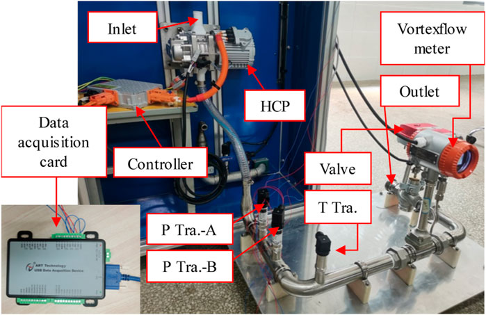
Figure 1. Test system physical picture.
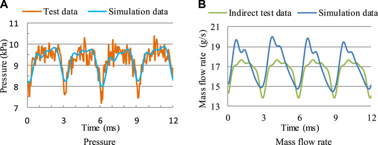
Figure 2. Comparison of test data and simulation data. (A) Pressure (B) Mass flow rate.
3 Multifactor and multi-objective coupling design method
3.1 Multifactor design condition
The design parameters of the HCP labeled in Figure 3 are divided into two categories: invariant parameters and variable parameters, as shown in Table 1. The invariant parameters include the width W and the height H of the pump cavity, the radial clearance δ1 between the rotor and the pump casing, and the radial clearance δ2 between rotors. The variable parameters include the diameter-to-pitch ratio κ, the blade number Z, and the helix angle φ. Design the elliptical profile of the HCP based on the design formula proposed in the reference (Zhai et al., 2022). It can be found that there is a certain correlation between the diameter-to-pitch ratio κ and the blade number Z. The smaller the κ value, the higher the maximum number of rotor blades Z that can be designed. When the value of κ is large, the rotor profile will experience the self-crossing phenomenon. For example, when κ = 1.47, only 2-blade and 3-blade rotors can be designed, and the conjugate curve will undergo a self-crossing phenomenon while designing 4-blade rotors. Similarly, the maximum number of rotor blades that can be designed is 4 when κ = 1.39, and 5 when κ = 1.32. After the blade number Z is determined, the rotor helix angle φ can be changed to obtain different HCP models. Considering the symmetry of the left and right rotors, the maximum helix angle is taken as 180°/Z. Therefore, the three variable parameters of the diameter-to-pitch ratio κ, the blade number Z, and the helix angle φ are used as design factors for the hydrogen circulation pump, with each design factor containing a series of numerical values. Therefore, three variable parameters are considered multiple factors in the design of the HCP, with each design factor containing a series of numerical values.
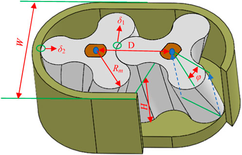
Figure 3. Marking of design parameters for the HCP.
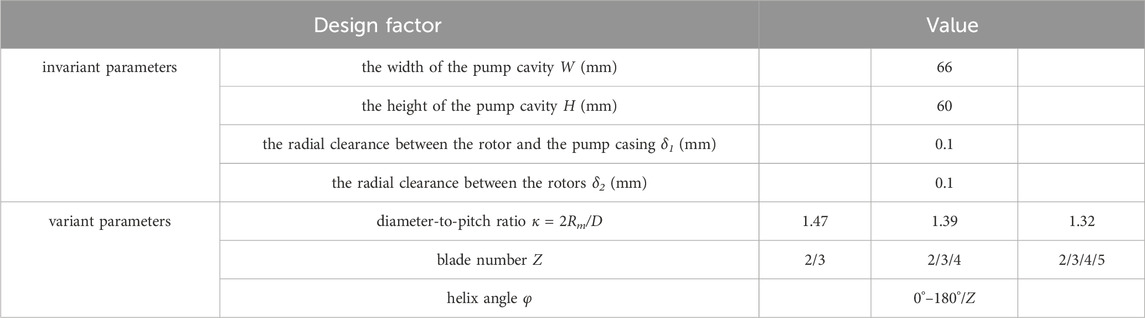
Table 1. Invariant and variable parameters of the HCP.
3.2 Definition of the multi-objective optimization function
The average flow rate is the main indicator to measure the delivery capacity of the HCP, which directly affects the efficiency of the fuel cell system. As a positive displacement pump, the output flow rate and pressure of the HCP have periodically fluctuated. The flow and pressure pulsation characteristics will have a certain impact on the stability of the fuel cell system and are also important indicators to measure the performance of HCP. Therefore, optimizing the design of multi-objective parameters such as average flow rate, flow pulsation, and pressure pulsation can develop HCP products with the best comprehensive performance.
Take the average flow rate actually output as the target parameter to measure the flow rate. Record the ratio of the real-time flow fluctuation amplitude to the average flow rate as the flow fluctuation factor KQ, which is the target parameter to measure the amplitude of flow fluctuation. Record the ratio of the real-time pressure fluctuation amplitude to the average outlet relative pressure as the pressure fluctuation factor KP, as the target parameter to measure the pressure fluctuation amplitude.
Define the multi-objective optimization function, see Eq. 1:
In the equation,
3.3 Multifactor and multi-objective coupling design process
Considering that there are a series of values available for selection in terms of the diameter-to-pitch ratio κ, the blade number Z, and the helix angle φ. Any combination of parameters will correspond to different multi-objective optimization function values. If all combinations are calculated to obtain the maximum value of the multi-objective optimization function, the computational workload is very large, and a reasonable multi-objective optimization process needs to be designed to quickly achieve the optimal assignment of parameters.
Figure 4 shows the multifactor and multi-objective coupling design process. Firstly, under the condition of a certain number of blades Z0, design straight blade rotor models with different diameter-to-pitch ratios κ and conduct simulation, calculate the value of the multi-objective optimization function
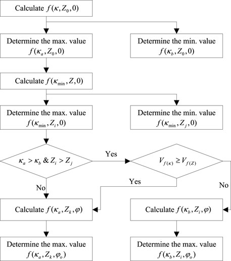
Figure 4. Flow chart of multi-objective optimization method.
In the two equations,
Based on the comparison results, choose to design the rotor profile with the maximum number of blades
4 Analysis of the influence of design factors
Define the expression of the HCP to reflect its parameter configuration, such as expressing the HCP with diameter-to-pitch ratio
4.1 The influence of diameter-to-pitch ratio on the performance of HCP
The influence analysis of the diameter-to-pitch ratio is conducted under the condition of 3 rotor blades. Figure 5 shows the comparison of the flow rate and the pressure of HCP under different diameter-to-pitch ratios. Firstly, analyze the impact of diameter-to-pitch ratio on the average flow rate of HCP: the average flow rate of the HCP147-3-0 model is 45.0 Nm3/h, the HCP139-3-0 model is 37.0 Nm3/h, the HCP132-3-0 model is 33.6 Nm3/h, indicating a directly proportional relationship between the diameter-to-pitch ratio and the average flow rate. Secondly, analyze the impact of diameter-to-pitch ratio on the real-time flow pulsation characteristics of HCP: on the one hand, when the diameter-to-pitch ratio changes, the pulsation frequency of the flow rate waveform, the positions of the peaks and valleys do not change, and the similarity of the waveform is high; on the other hand, the flow pulsation value of the HCP147-3-0 model is
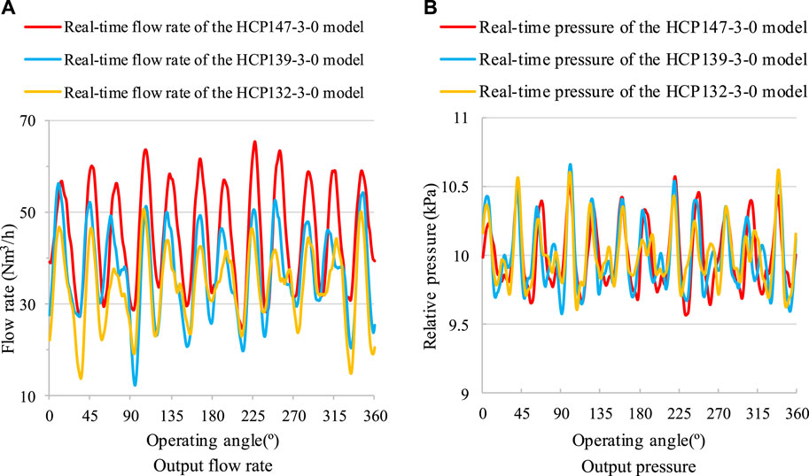
Figure 5. Performance of HCP models with different diameter-to-pitch ratios. (A) Output flow rate (B) Output pressure.
Figure 6 shows the back-flow at the radial clearance of different diameter-to-pitch ratio models. The back-flow velocity at the clearance of the HCP147-3-0 model is 728 m/s, the HCP139-3-0 model is 720 m/s, and the HCP132-3-0 model is 641 m/s. From this, it can be concluded that the back-flow rates at the clearance of the HCP147-3-0 model and the HCP139-3-0 model are similar, and the HCP132-3-0 model is relatively low. Analyzing the absolute decrease of the average output flow rate of the three models relative to the theoretical flow rate, the theoretical flow rate of the HCP147-3-0 model is 75.1 Nm3/h, which decreases by 30.1 Nm3/h under the 1.1 pressure ratio condition, the HCP139-3-0 model is 67.2 Nm3/h, which decreased by 30.2 Nm3/h under the 1.1 pressure ratio condition, and the HCP132-3-0 model is 59.4 Nm3/h, which decreased by 25.8 Nm3/h under the 1.1 pressure ratio condition. The absolute decrease value results are consistent with the analysis results of the back-flow rate at the clearance, indicating that the decrease in leakage caused by a decrease in the diameter-to-pitch ratio of the HCP is weaker than the decrease in delivery capacity caused by a decrease in the area utilization coefficient, resulting in a decrease in the final output flow rate.
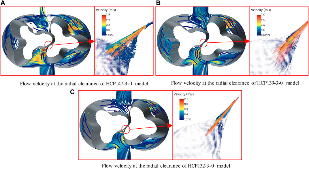
Figure 6. Radial clearance flow velocity comparison of HCPs with different diameter-to-pitch ratios. (A) Flow velocity at the radial clearance of HCP147-3-0 model (B) Flow velocity at the radial clearance of HCP139-3-0 model (C) Flow velocity at the radial clearance of HCP132-3-0 model.
Figure 7 shows the comparison of the internal pressure distribution of HCP models under different diameter-to-pitch ratios. It can be found that in the first two states, the maximum pressure of the HCP132-3-0 model is basically the same as that of the HCP147-3-0 model, but in the third state, the maximum pressure of the HCP132-3-0 model is significantly lower than that of the HCP147-3-0 model, which is consistent with the trend of the pressure fluctuation factor of each model in Figure 5B.
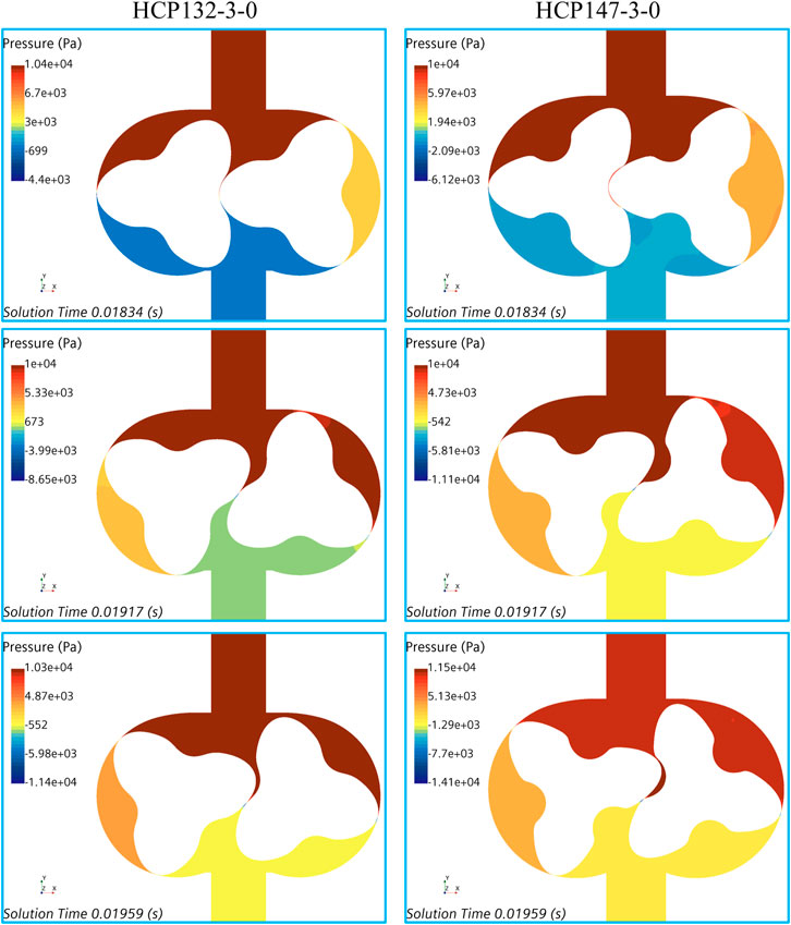
Figure 7. Pressure distribution comparison of HCP models with different diameter-to-pitch ratios.
4.2 The influence of blade number on the performance of HCP
Design HCP models with different blade numbers at the lowest diameter-to-pitch ratio for simulation calculations. Figure 8 shows the comparison of the flow rate and the pressure of HCP under different blade numbers. Firstly, analyze the impact of blade number on the average flow rate of HCP: the average flow rate of the HCP132-2-0 model is 32.4 Nm3/h, the HCP132-3-0 model 33.6 Nm3/h, the HCP132-4-0 model 36.1 Nm3/h, and the HCP132-5-0 model 38.0 Nm3/h, indicating a directly proportional relationship between the blade number and the average flow rate. Secondly, analyze the impact of blade number on the real-time flow pulsation characteristics of HCP: on the one hand, when the rotor operates for one cycle (360°), the number of periodic flow pulsation waveforms output by the HCP132-2-0 model is 4, the HCP132-3-0 model is 6, the HCP132-4-0 model is 8, and the HCP132-5-0 model is 10, indicating that the number of pulsation waveforms output by the HCP during one operating cycle is twice the number of rotor blades; on the other hand, the flow pulsation value of the HCP132-2-0 model is
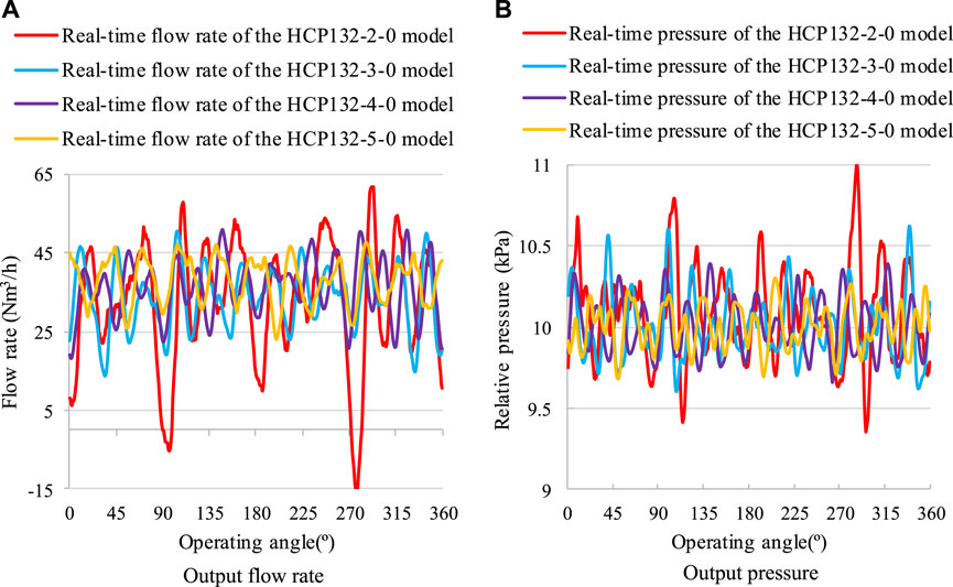
Figure 8. Performance of HCP models with different blade numbers. (A) Output flow rate (B) Output pressure.
Figure 9 shows the back-flow at the radial clearance of different blade number models. The back-flow velocity at the clearance of the HCP132-2-0 model is 677 m/s, the HCP132-3-0 model is 561 m/s, the HCP132-4-0 model is 453 m/s, and the HCP132-5-0 model is 441 m/s, indicating that the back-flow rate at the clearance of the HCP model decreases as the number of rotor blades increases. Analyze the absolute decrease of the average output flow rate relative to the theoretical flow rate, while the theoretical flow rates of the four models are not significantly different. The HCP132-2-0 model decreased by 26.6 Nm3/h under 1.1 pressure ratio conditions, the HCP132-3-0 model decreased by 25.8 Nm3/h, the HCP132-4-0 model decreased by 24.0 Nm3/h, and the HCP132-5-0 model decreased by 23.0 Nm3/h. This result is consistent with the analysis results of the back-flow rate at the clearance.
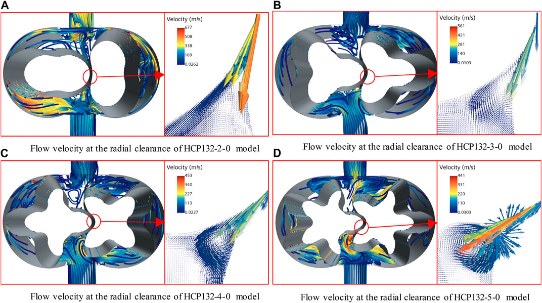
Figure 9. Variation of flow velocity at the radial clearance in HCP models with different blade numbers. (A) Flow velocity at the radial clearance of HCP132-2-0 model (B) Flow velocity at the radial clearance of HCP132-3-0 model (C) Flow velocity at the radial clearance of HCP132-4-0 model (D) Flow velocity at the radial clearance of HCP132-5-0 model.
Figure 10 shows the comparison of the internal pressure distribution of HCP models under different blade numbers. It can be found that in any state, the maximum pressure of the HCP132-2.0 model is the highest, followed by the HCP132-4-0 model, and the HCP132-5-0 model is the lowest. The maximum pressure fluctuation amplitude of the HCP132-2.0 model is 1.2 kPa, the HCP132-4-0 model is 0.6 kPa, and the HCP132-5-0 model is 0.4 kPa. The results show that the more blades the rotor has, the smaller the pressure fluctuation inside the pump chamber, and the lower the amplitude of the output pressure fluctuation, which is consistent with the trend of the pressure fluctuation factor of each model in Figure 8B.
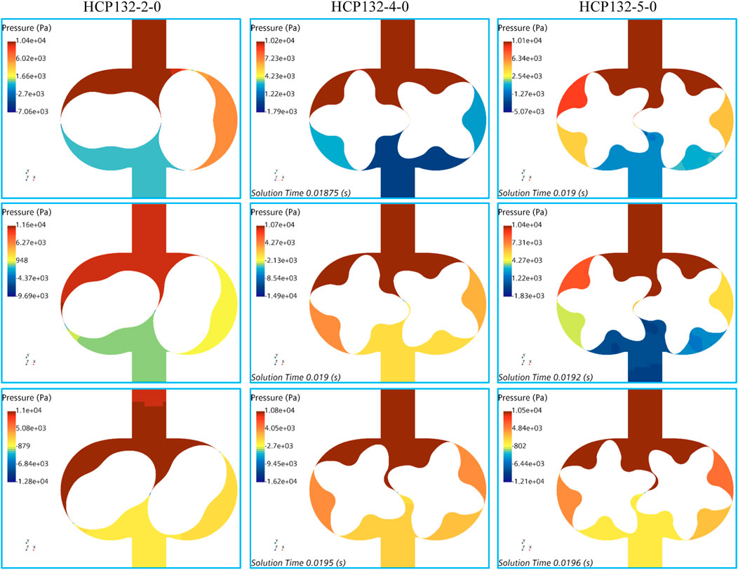
Figure 10. Pressure distribution comparison of HCP models with different blade numbers.
4.3 Phase comparison of the models
According to the multifactor and multi-objective coupling design method, the optimal stage selection of the HCP model is carried out in the following stages.
(1) Based on the simulation calculation results, calculate the objective functions
(2) Based on the calculation results,
(3) As
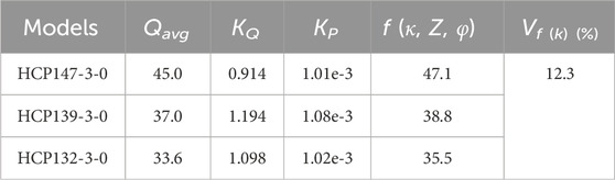
Table 2. Calculation of HCP models under different diameter-to-pitch ratios.
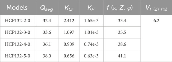
Table 3. Calculation of HCP models with different blade numbers.
4.4 The influence of helix angle on the performance of HCP
Figure 11 shows the average flow rate, flow pulsation value, and pressure pulsation value changes of different helix angle models, used to summarize the influence of helix angle on the flow characteristics of the HCP. Firstly, analyze the impact of the helix angle on the average flow rate of HCP: as the helix angle increases, the average flow rate of the HCP gradually decreases within the range of 0°–22.5°, and increases within the range of 22.5°–60°; the HCP147-3-22.5 model with a helix angle of 22.5° has the smallest average flow rate of 33.6 Nm3/h, and the HCP147-3-60 model with a helix angle of 60° has the highest average flow rate of 45.1 Nm3/h, which is equivalent to the flow rate of the straight blade rotor model. Secondly, analyze the impact of the helix angle on the real-time flow pulsation characteristics of HCP: as the helix angle increases, the average flow rate of the HCP gradually increases within the range of 0°–15°, and decreases within the range of 15°–60°; the model with a helix angle of 15° has the maximum flow pulsation value of
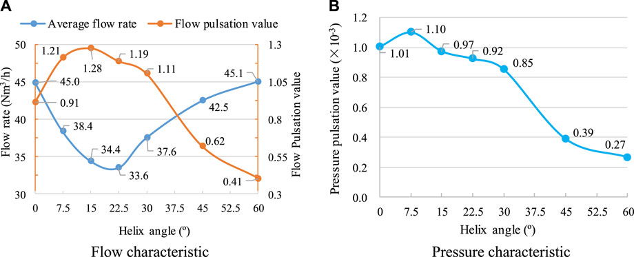
Figure 11. Changes in fluid characteristics of HCP models with different helix angles. (A) Flow characteristic (B) Pressure characteristic.
The change in helix angle does not change the theoretical flow rate of the HCP model but causes a change in the actual output flow rate, which is because the change in helix angle can cause a change in the back-flow rate at the clearance. Figure 12 shows the flow velocity vectors of the horizontal and vertical sections at the middle position of the HCP models under different helix angles, used for in-depth analysis of the influence of helix angles on the back-flow at the clearance. Analyzing the flow velocity at the clearance, it is found that the maximum flow velocity decreases with the increase of the helix angle. However, an increase in helix angle will result in an extension of the length of the meshing clearance, which in turn leads to an increase in the cross-sectional area of the back-flow. Under the combined effect of reduced back-flow velocity and increased clearance cross-sectional area, the average flow rate at a 22.5° helix angle is minimized.
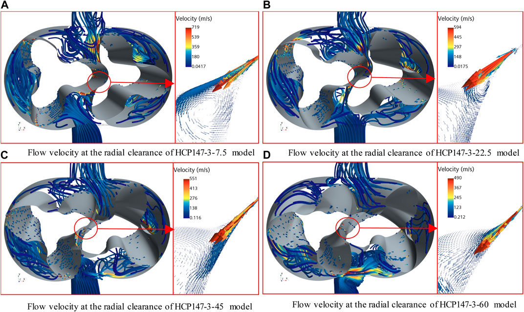
Figure 12. Variation of flow velocity at the radial clearance in HCP models with different helix angles. (A) Flow velocity at the radial clearance of HCP147-3-7.5 model (B) Flow velocity at the radial clearance of HCP147-3-22.5 model (C) Flow velocity at the radial clearance of HCP147-3-45 model (D) Flow velocity at the radial clearance of HCP147-3-60 model.
Figure 13 shows the comparison of the internal pressure distribution of HCP models under different helix angles. It can be found that the average pressure difference between the high-pressure and low-pressure areas inside the HCP147-3-22.5 model is 16.7 kPa, while the HCP147-3-45 model is 15.2 kPa and the HCP147-3-60 model is 15.0 kPa. This indicates that the larger the helix angle, the smaller the internal pressure difference, which is consistent with the trend of the pressure fluctuation factor of each model in Figure 11B. Analyzing its internal mechanism, as the helix angle increases and the volume of the high-pressure zone also increases, the longer the high pressure can be maintained, the smoother the output pressure curve.
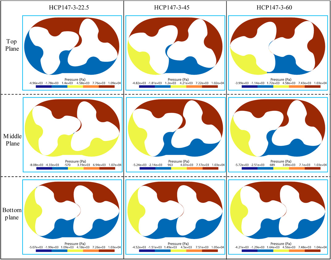
Figure 13. Pressure distribution comparison of HCP models with different helix angles.
5 Determination and verification of the optimal parameter configuration
5.1 Determination of the optimal parameter configuration
According to the multi-objective optimization design method, the effects of two parameters, namely, the diameter-to-pitch ratio and the blade number, on the flow characteristics of the HCP are first analyzed, and the optimal stage model HCP147-3-0 is obtained through comparison. Afterward, rotor models with different helix angles are designed based on the stage optimal model, and the relationship between helix angles and flow characteristics is analyzed.
Table 4 shows the multi-objective optimization function values for different helix angle models. It can be found that the HCP147-3-60 model has the highest value of the multi-objective optimization function
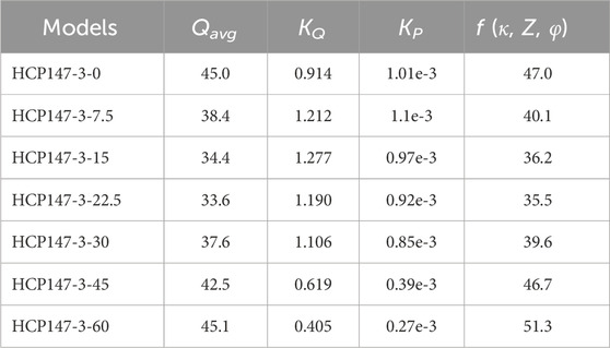
Table 4. Calculation of multi-objective optimization functions under different helix angles.
5.2 Verification of the optimal parameter configuration
Select some examples with relatively obvious performance advantages to compare with the optimal model HCP147-3-60. Figure 14 shows the performance comparison between the HCP132-5-36 model, the HCP132-5-0 model, and the optimal configuration model. Comparing the flow curves of the HCP132-5-36 model with the HCP132-5-0 model, the average flow rate increased from 37.9 Nm3/h to 42.5 Nm3/h after the straight blade rotor became a spiral rotor, the flow fluctuation value decreased from 0.657 to 0.454, and the pressure fluctuation value decreased from 0.63 × 10⁻³ to 0.33 × 10⁻³, indicating that the overall performance of the HCP132-5-36 model is better than that of the HCP132-5-0 model. However, compared with the HCP147-3-60 model, the average flow rate of the HCP132-5-36 model is relatively low, and the flow fluctuation value and pressure fluctuation value are relatively high, resulting in relatively poor overall performance. After calculation, the multi-objective optimization function value of the HCP132-5-36 model is slightly smaller than that of the HCP147-3-60 model, verifying that the HCP147-3-60 model is the optimal configuration model.
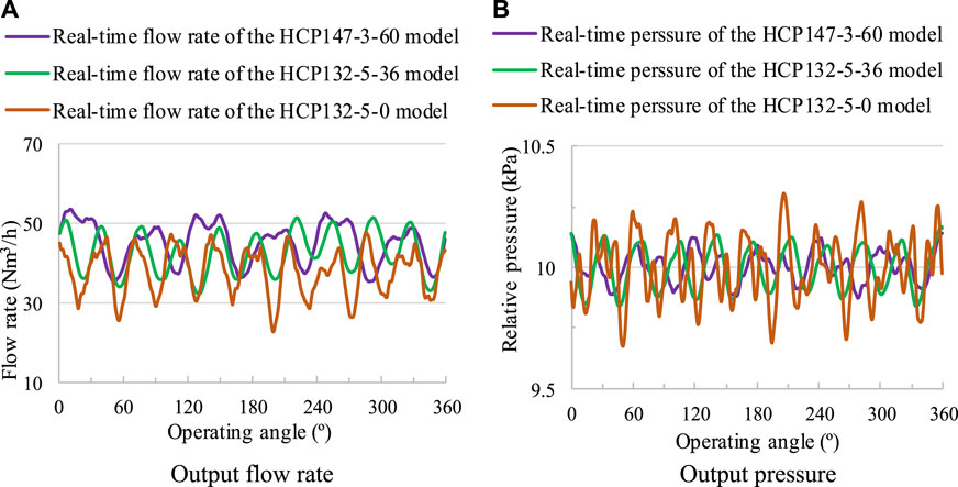
Figure 14. Performance comparison between the optimal configuration model and the example model. (A) Output flow rate (B) Output pressure.
6 Conclusion
This article proposes a multifactor and multi-objective coupling design method based on the elliptical profile. By calculating and analyzing the effects of factors such as diameter-to-pitch ratio, blade number, and helix angle on the performance of HCPs based on the verified overset grid simulation method, the optimal configuration of the HCP model is determined, and the optimal results are verified through examples. The main conclusions formed are as follows:
(1) A multifactor and multi-objective coupling design method is proposed. A multi-objective optimization function has been defined, which can adapt to different needs by adjusting the weight factor of the flow pulsation value and the pressure pulsation value. A multifactor and multi-objective coupling design process has been established, and the optimal stage model is determined by comparing the influence factors of the diameter-to-pitch ratio and the blade number on the objective function. Based on this, the influence of the helix angle is considered to determine the optimal model. The proposed coupling design method can effectively achieve the optimal parameter configuration of the HCP, which is beneficial for improving the overall performance.
(2) The effects of design parameters such as diameter-to-pitch ratio, blade number, and helix angle on the flow characteristics of HCP are studied. It is found that the average flow rate of the HCP is directly proportional to the diameter-to-pitch ratio and the blade number, gradually decreases in the range of helix angle from 0° to 22.5°, and increases in the range of helix angle from 22.5° to 60°. The flow pulsation value and pressure pulsation value of the HCP are less affected by the diameter-to-pitch ratio, decrease with the increase of the blade number, and show a trend of first increasing and then decreasing with the increase of the helix angle, and both reach their minimum values when the helix angle is 60°.
(3) The optimal parameter configuration of the HCP model has been completed, and the optimal model is determined as HCP147-3-60, with a diameter-to-pitch ratio κ = 1.47, rotor blade number Z = 3, helix angle φ = 60°. The average flow rate of the optimal model is 45.1 Nm3/h, the flow pulsation value KQ = 0.405, the pressure pulsation value KP = 0.27 × 10⁻³, and the multi-objective optimization function value is 51.3. The design result is validated using another model HCP132-5-36 with significant performance advantages, the multi-objective optimization function value of which is slightly lower than the optimal model HCP147-3-60. The comparison results verified the feasibility of the multifactor and multi-objective coupling design method.
7 Recent developments and future directions
HCP has gradually become a hot spot in the development of the fuel cell industry, which is significant to the advancement of fuel cell industrialization in the future. In recent years, numerous researches have been conducted on the internal flow characteristics of the HCP. However, there are still some knowledge gaps, especially, the HCP generates significant noise during operation due to the high-speed rotation of the rotor and gas compression, which reduces user comfort and is of great research significance and difficulty. It has become an important research direction in the future.
Data availability statement
The original contributions presented in the study are included in the article/supplementary material, further inquiries can be directed to the corresponding author.
Author contributions
HZ: Writing–original draft, Writing–review and editing. WL: Writing–review and editing. JL: Writing–review and editing, Data curation. CS: Writing–review and editing, Software. LJ: Writing–review and editing, Methodology. YX: Writing–review and editing, Methodology.
Funding
The author(s) declare that financial support was received for the research, authorship, and/or publication of this article. The work was sponsored by the sixth phase of the “169 Project” scientific research project in Zhenjiang, the National Natural Science Foundation of China (No. 52179085), the National Key R&D Program Project (No. 2020YFC1512405), the Sixth “333 High Level Talented Person Cultivating Project” of Jiangsu Province, Funded projects of “Blue Project” in Jiangsu Colleges and Universities.
Conflict of interest
YX was employed by the Beijing Drainage Group.
The remaining authors declare that the research was conducted in the absence of any commercial or financial relationships that could be construed as a potential conflict of interest.
Publisher’s note
All claims expressed in this article are solely those of the authors and do not necessarily represent those of their affiliated organizations, or those of the publisher, the editors and the reviewers. Any product that may be evaluated in this article, or claim that may be made by its manufacturer, is not guaranteed or endorsed by the publisher.
References
Chen, Z. B., and Zou, Y. Z. (2019). The effect of rotor blade number on performance of rotor pump. Mach. Des. Manuf. 03, 196–199. doi:10.19356/j.cnki.1001-3997.2019.03.048
Gao, P. T. (2022). Flow field calculation and internal transient flow characteristics of hydrogen circulating pump. Jiangsu Univ. doi:10.27170/d.cnki.gjsuu.2022.002661
Gu, P. T., Xing, L. F., Wang, Y. F., Feng, J. M., and Peng, X. Y. (2021). A multi-objective parametric study of the claw hydrogen pump for fuel cell vehicles using Taguchi method and ANN. Int. J. Hydrogen Energy 46 (9), 6680–6692. doi:10.1016/j.ijhydene.2020.11.186
Li, D. T., He, Z. L., Sun, S. H., Wang, C., Chen, W. Q., and Xing, Z. W. (2021a). Development and analysis of novel six-lobe helical rotors for hydrogen fuel cell vehicle roots blowers. Int. J. Hydrogen Energy 46 (59), 30479–30493. doi:10.1016/j.ijhydene.2021.06.199
Li, L. (2021). Design of rotor geometric parameters and aerodynamic performance of cam gas circulating pump for fuel cell. Lanzhou Univ. Technol. doi:10.27206/d.cnki.ggsgu.2021.000632
Li, Q., Wang, H., and Huang, Z. Q. (2022). Research on influence of meshing clearance and number of rotor blades on pump performance. Chin. J. Process Eng. 22 (12), 1666–1675. doi:10.12034/j.issn.1009-606X.221438
Li, Y. B., Guo, D. S., and Tang, Y. L. (2020). Effect of the rotor diameter-length ratio on the rotary lobe pump performance based on numerical simulations and experimental tests. J. Vib. shock 39 (09), 194–200+220. doi:10.13465/j.cnki.jvs.2020.09.027
Li, Y. B., Li, L., and Liu, J. F. (2021b). Numerical study on the aerodynamic performance of multi-blade rotor cavity in the gas circulating pump of fuel cell. J. XiAn Jiaot. Univ. 55 (03), 46–56. doi:10.7652/xjtuxb202103006
Li, Y. B., Zhang, X. Z., Guo, D. S., and Wang, X. F. (2018). Numerical analysis and verification of flow characteristics of rotor cavity of spiral rotary lobe pump. Trans. CSAE 34 (10), 62–67. doi:10.11975/j.issn.1002-6819.2018.10.007
Liu, Y., Tu, Z. K., and Siew, H. C. (2021b). Applications of ejectors in proton exchange membrane fuel cells: a review. Fuel Process. Technol. 214, 106683. doi:10.1016/j.fuproc.2020.106683
Liu, Y., Tu, Z. K., and Siew, H. C. (2023a). Performance evaluation and degradation mechanism for proton exchange membrane fuel cell with dual exhaust gas recirculation. Adv. Energy Sustain. Res. 4, 22200180. doi:10.1002/aesr.202200180
Liu, Y., Tu, Z. K., and Siew, H. C. (2023b). Performance analysis and dynamic characteristics of a proton exchange membrane fuel cell with dual recirculation pumps for air-free applications. J. Power Sources 566, 232923. doi:10.1016/j.jpowsour.2023.232926
Liu, Y., Xiao, B., Zhao, J. J., Fan, L. X., Luo, X. B., Tu, Z. K., et al. (2021a). Performance degradation of a proton exchange membrane fuel cell with dual ejector-based recirculation. Energy Convers. Manag. X. 12, 100114. doi:10.1016/j.ecmx.2021.100114
Liu, Y. F., Fan, L., Pei, P. C., Yao, S. Z., and Wang, F. (2018). Asymptotic analysis for the inlet relative humidity effects on the performance of proton exchange membrane fuel cell. Apply Energy 213, 573–584. doi:10.1016/j.apenergy.2017.11.008
Rao, L., and Zhong, Y. C. (2021). Axial clearance effects on performance of gerotor pump using numerical simulation. Mach. Build. Automation 50 (05), 110–112. doi:10.19344/j.cnki.issn1671-5276.2021.05.029
Singh, G., Sun, S. H., Ahmed, K., Li, Q. H., and Bruecker, B. (2019). Transient flow analysis in a Roots blower: experimental and numerical investigations. Mech. Syst. Signal Process. 134, 106305. doi:10.1016/j.ymssp.2019.106305
Wang, Y. P., Ma, Q. Y., and Zhao, H. H. (2019). Fuel cell engine technology overview. Automot. Dig. 01, 42–47.
Wiebe, W., Thomas, U., and Sven, S. (2020). Hydrogen pump for hydrogen recirculation in fuel cell vehicles. E3S Web Conf. 155, 01001. doi:10.1051/e3sconf/202015501001
Xing, Y. Z., Li, Y. B., and Zhang, S. F. (2023). Effects of helical angle on performance and flow pulsation characteristics of aviation fuel gear pump. J. Propuls. Technol. 44 (03), 142–153. doi:10.13675/j.cnki.tjjs.2205089
Yang, Y. M. (2022). Fuel cell gas circulating pump rotor chamber internal transient research on the flow and pneumatic properties. Lanzhou Univ. Technol. doi:10.27206/d.cnki.ggsgu.2022.001413
Yang, Y. M., Zhang, Z. Y., and Li, L. (2022). Influence of rotor diameter-distance ratio on performance of fuel cell gas circulating pump. J. Aerosp. Power 37 (09), 1970–1978. doi:10.13224/j.cnki.jasp.20210348
Zhai, H. L., Li, W., Ji, L. L., Li, J. W., Li, S., et al. (2022). Profile design and performance research of hydrogen circulation pump in fuel cell system. Mechanika 28 (4), 283–293. doi:10.5755/j02.mech.31528
Zhai, H. L., Li, W., Ji, L. L., Li, S., Cao, Y. H., and Li, Y. K. (2023). Research on measurement method for high-frequency pulsation flow of hydrogen circulating pump. Int. J. Hydrogen Energy 48 (39), 14853–14865. doi:10.1016/J.IJHYDENE.2022.12.358
Zhang, Q. Q., Feng, J. M., Zhang, Q. Q., and Peng, X. Y. (2019). Performance prediction and evaluation of the scroll-type hydrogen pump for FCVs based on CFD-Taguchi method. Int. J. Hydrogen Energy 44 (29), 15333–15343. doi:10.1016/j.ijhydene.2019.04.019
Zhang, X. Z. (2018). Influence of rotor geometric parameters on flow characteristics of rotary lobe pump. Lanzhou Univ. Technol.
Zhou, S., Fan, L., Zhang, G., Gao, J. H., Lu, Y., Zhao, P., et al. (2022). A review on proton exchange membrane multi-stack fuel cell systems: architecture, performance, and power management. Appl. Energy 310, 118555. doi:10.1016/j.apenergy.2022.118555
Zhou, S. M., Jia, X. H., Yan, H. M., and Peng, X. Y. (2021). A novel profile with high efficiency for hydrogen-circulating Roots pumps used in FCVs. Int. J. Hydrogen Energy 46 (42), 22122–22133. doi:10.1016/j.ijhydene.2021.04.038
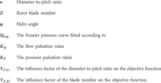
Nomenclature
Keywords: hydrogen circulation pump (HCP), optimal parameter configuration, flow pulsation, pressure pulsation, overset mesh
Citation: Zhai H, Li W, Li J, Shen C, Ji L and Xu Y (2024) Multifactor and multi-objective coupling design of hydrogen circulation pump. Front. Energy Res. 12:1358911. doi: 10.3389/fenrg.2024.1358911
Received: 20 December 2023; Accepted: 08 March 2024;
Published: 20 March 2024.
Edited by:
Xiaohu Yang, Xi’an Jiaotong University, ChinaReviewed by:
Benqing Liu, Yangzhou University, ChinaGuilin Hu, Zhejiang University of Science and Technology, China
Zhengkai Tu, Huazhong University of Science and Technology, China
Copyright © 2024 Zhai, Li, Li, Shen, Ji and Xu. This is an open-access article distributed under the terms of the Creative Commons Attribution License (CC BY). The use, distribution or reproduction in other forums is permitted, provided the original author(s) and the copyright owner(s) are credited and that the original publication in this journal is cited, in accordance with accepted academic practice. No use, distribution or reproduction is permitted which does not comply with these terms.
*Correspondence: Huanle Zhai, anN6aGFpaGxAMTYzLmNvbQ==