 Weikang Kong
 Yongjun Zhou2
- 1State Grid Xizang Electric Power Research Institute, Lhasa, China
- 2State Grid Lasa Power Supply Company, Lhasa, China
- 3State Grid Xizang Electric Power Company Limited, Lhasa, China
Introduction: Grid-forming (GFM) converters with DC-voltage controller can emulate inertia and support frequency stability while maintaining a stable DC voltage, making this method well-suited for PV systems. However, the introduction of the DC voltage control loop exacerbates the issue of low-frequency oscillations in GFM converters. Although existing studies have identified negative resistance behavior through impedance analysis, t the overall impedance characteristics of the unit make it difficult to pinpoint the key sources of internal negative damping, posing challenges for the design of oscillation suppression strategies.
Methods: Building on this, by applying the damping torque method, this paper analyzes the components of damping torque and synchronizing torque in DC-voltage controller based GFM (DC-GFM) converter and the stability conditions of multi-converter systems. This provides a clear explanation of the underlying mechanism behind negative damping and the influence of control parameters.
Result: The analysis reveals that the negative damping originates from the integral parameters in the DC-voltage controller. Based on this insight, a damping enhancement strategy for multi-DC-GFM system is proposed. The simulation results validate the effectiveness of both the parameter analysis and the proposed strategy.
Discussion: Finally, the limitations of this paper and the future research directions are discussed.
1 Introduction
With the accelerating transition of power systems, renewable energy sources like photovoltaics (PVs) are making up a larger portion of the generation mix. However, because they are generally grid-connected via phase-locked loop–based grid-following control, the inertia of the system is progressively reduced. Major blackout events in countries such as Australia and the UK have been confirmed to be closely related to the decline in system inertia caused by the large-scale integration of renewable energy sources (Commission, 2019; ESO, 2019). In contrast, grid-forming (GFM) converters, which autonomously establish voltage and frequency, are capable of providing inertia support and actively regulating the grid, and have received widespread attention from both academia and industry in recent years (Liu et al., 2016; Li M. et al., 2022; Wang et al., 2025; Rahman et al., 2024; Ji et al., 2024).
Currently, the main control strategies for GFM converters include droop control (Guerrero et al., 2011; Tayab et al., 2017), virtual synchronous generator (VSG) control (Zhong and Weiss, 2011; Driesen and Visscher, 2008; Su et al., 2025), virtual oscillator control (Johnson et al., 2014; Dhople et al., 2013), and DC-voltage controller based GFM (DC-GFM) control—also known as matching control (Guo et al., 2021; Zhao et al., 2023a; Jouini et al., 2016; Hu et al., 2023). Both droop control and VSG control emulate the external characteristics of synchronous machines, and existing studies have shown that they are approximately equivalent in dynamic behavior (Arco and Suul, 2014). When these two control strategies are used to provide frequency support to the grid, a constant DC voltage and additional power reserve is typically required on the DC side. Therefore, when PV systems adopt either of these grid-forming control methods, they must operate below the maximum power point or incorporate energy storage, leading to resource underutilization or increased investment (Hui Liu et al., 2024). The virtual oscillator is implemented based on the principle of limit cycles in nonlinear systems (Li J. et al., 2022). Due to its complex implementation and lack of intuitive interpretability, its application in large power grids remains limited. In contrast, DC-GFM control provides inertia and frequency support to the system through the DC-side capacitance. It has low power reserve requirements for the grid-side source, and its synchronization mechanism is similar to that of synchronous machines, offering strong interpretability. This makes it particularly promising for renewable energy sources with power limitations, such as PV and wind power.
However, the establishment of the synchronization mechanism between the DC voltage and AC frequency also provides an additional channel for disturbances to transfer between the AC and DC sides, potentially leading to severe low-frequency oscillations (LFOs) in the system. In reference (Zhao et al., 2023a), the root locus of DC-GFM control without AC power feedback was analyzed, and the results showed that a pair of poles consistently appears in the low-frequency range of the right half-plane. In reference (Guo et al., 2021), the impedance characteristics of DC-GFM control under two different power feedback controls were analyzed, revealing that both controls exhibited a portion of negative resistance in the 2–9 Hz range. In reference (Liu et al., 2025), it compared the stability of VSG control and DC-GFM control under different grid strengths, and the results indicated that the system using DC-GFM control may experience oscillatory instability under strong grid conditions. The above studies indicate that the LFO modes in DC-GFM control pose a risk of system instability. However, the related stability analyses are primarily based on the eigenvalue distribution or impedance characteristics of the overall system, making it difficult to clearly identify the mechanisms behind negative damping and to provide targeted guidance for the design of low-frequency oscillation suppression strategies.
To enhance the small-signal stability of DC-GFM control, some researchers have proposed several effective suppression strategies. In references (Jouini et al., 2016; Arghir and Dörfler, 2020), parallel resistors are added at the DC capacitor to simulate converter switching losses, thereby improving the damping capability of the system. However, the presence of resistors results in unnecessary power loss, reducing the energy transmission efficiency. In reference (Zhao et al., 2023b), it proposes an oscillation damping strategy based on a notch filter, which enhances low-frequency damping by reshaping the gain of the power feedback loop. However, the damping ratio of the notch filter affects both synchronization and LFO mitigation, leading to a trade-off in parameter design. In reference (Ai et al., 2024), an equivalent damping strategy based on power feedback is introduced. The damping effect is achieved by leveraging the mismatch between the renewable generation and the output power of converter. Thus, the damping capability it provides is limited and may lead to reduced converter efficiency. A parameter alternating controller applicable to DC-GFM system was introduced in reference (Wang et al., 2020). Although it enhances the overall damping of system, it may fall short of delivering optimal damping for individual oscillation modes. In reference (Zhao et al., 2023a), a method based on feeding the q-axis voltage back into the frequency control loop was proposed. However, this control approach may introduce coupling between voltage and frequency dynamics.
Overall, existing research have made some progress in analyzing the stability of DC-GFM converters and in developing damping enhancement strategies; however, they primarily focus on single-converter systems. As a result, they fall short in revealing the stability mechanisms in multi-converter systems, and the applicability of proposed damping strategies in such systems remains uncertain. Based on this, this paper analyzes the LFOs in DC-GFM systems using the damping torque method. The main contributions are as follows.
a. The torque components in DC-GFM converters are analyzed, revealing the mechanism behind the generation of negative damping torque and how various control parameters influence it.
b. The stability mechanism of multiple DC-GFM converters parallel system is revealed: as long as the damping torque coefficient of each DC-GFM converter is positive, the entire system remains stable.
c. A damping enhancement strategy applicable to multi-DC-GFM systems is proposed. By introducing power feedback, additional damping torque is provided to compensate for the negative damping introduced by the DC voltage control, thereby improving the overall system stability.
The remainder of this paper is organized as follows: first, Section 2 presents a complete small-signal model of the system, and analyzes the influence of different control parameters on LFOs. Section 3 then analyzes the torque composition of the DC-GFM and derives the stability conditions for a multi-converter DC-GFM system. Based on this analysis, a damping enhancement strategy is proposed. In Section 4, simulations are conducted to verify both the accuracy of the parameter analysis and the performance of the proposed approach. Section 5 outlines the applicability of this paper and highlights future research opportunities. Section 6 finally concludes the paper.
2 System modeling and analysis of parameter influence
2.1 Small-signal model of DC-GFM system
Figure 1 shows the topology and control block diagram of a grid-forming PV system based on DC-voltage controller (hereinafter referred to as the DC-GFM system). Here, Pin is the output power of the PV array, and Pdc is the power injected into the converter. Cdc denotes the DC-side capacitor. Lf and Rf represent the filter inductor and equivalent resistance, respectively; Cf is the filter capacitor; Lg and Rg correspond to the grid-side inductance and equivalent resistance. If denotes the current at the converter port, while Io and Vo represent the output current and voltage of the converter, respectively. The converter employs a DC-GFM control strategy, which mainly includes a DC voltage control loop, active power control loop, reactive power control loop, and a dual-loop control for voltage and current. Vdcref denotes the reference voltage on the DC side; P0 and Q0 are the reference active and reactive power outputs of the converter; Vref and ω0 represent the rated output voltage and frequency, respectively. Pe and Qe represent the active and reactive power outputs of the converter, respectively, while ω and θ denote the angular frequency and voltage phase angle at the converter output.
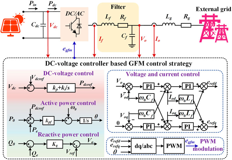
Figure 1. The schematic diagram of DC-GFM system.
Based on the power balance on the DC side, the dynamic of the DC voltage can be derived as:
Assuming the PV operates under maximum power point tracking and irradiance and temperature remain constant, the output power of the PV array Pin is steady. By expressing the variables in Equation 1 as the sum of their steady-state and perturbation components, the following expression can be obtained:
By eliminating the steady-state and higher-order perturbation components, the resulting relationship between the DC voltage and the DC output power is:
By neglecting the power losses in the converter, Pdc in Equation 3 can be substituted with the output power of the converter Pe. The voltage and current dynamics across the LCL filter are given by:
Therefore, based on Equations 4–6, the output power of the converter can be derived using the instantaneous power theory as:
In DC-GFM, the DC voltage control loop maintains a constant DC voltage via a PI controller. Its control equation is given by:
Here, Pdcref is the output of the DC voltage control loop and serves as the reference input for the active power control loop. The active power control loop employs a proportional controller to regulate the output active power of converter and establish its frequency. The control equation is given by:
Here, kpf is the proportional gain of the active power control loop. The reactive power control loop adjusts the output reactive power of the converter and establishes the AC voltage. Its control equation is:
Subsequently, the output of the reactive power control loop is used as the input to the voltage and current control loop for rapid tracking of the grid-side voltage and current variations. Since the time scale of the voltage and current control loop is typically much faster than that of the power control loop, the dynamics of the voltage and current control loop can be neglected when studying the power-frequency dominated LFO issue (Qu et al., 2021). Therefore, the state space formed by Equations 1–10 can provide a detailed description of the system dynamics when low-frequency disturbances occur in the grid, namely,:
Where Xsys is the state variable matrix of the state space, U and Ysys represent the input and output matrices, respectively. A, B, C and D are the corresponding state-space matrices. Figure 2 presents the waveforms obtained from the theoretical model based on Equation 11 and the hardware-in-the-loop experiment, under a 0.4 MW load disturbance on the grid side occurring at 8 s. The close agreement between the two curves confirms the reliability of the developed state-space model.
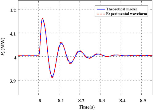
Figure 2. Comparison between the theoretical and simulation models.
2.2 Analysis of parameter impact and associated stability risks
To investigate how control parameters affect LFOs in the DC-GFM system, root locus diagrams corresponding to parameter variations are plotted based on Equation 11. Figures 3–5 respectively show how the root locus of the LFO mode evolves with increasing proportional gain kp and integral gain ki of the DC voltage control loop, and the proportional gain kpf of the active power control loop. As shown in Figure 3, as kp increases, the imaginary part of the eigenvalue corresponding to the LFO mode increases steadily, while the real part first increases and then decreases. The magnitude of change in the imaginary part is significantly greater than that of the real part, indicating that increasing kp has limited impact on the duration of LFOs under the same disturbance, but it does result in a higher oscillation frequency.
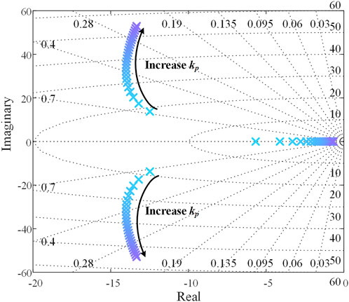
Figure 3. Root locus plot of the variation in the kp parameter.
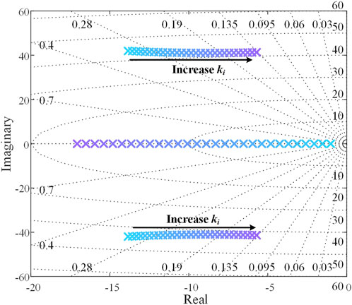
Figure 4. Root locus plot of the variation in the ki parameter.
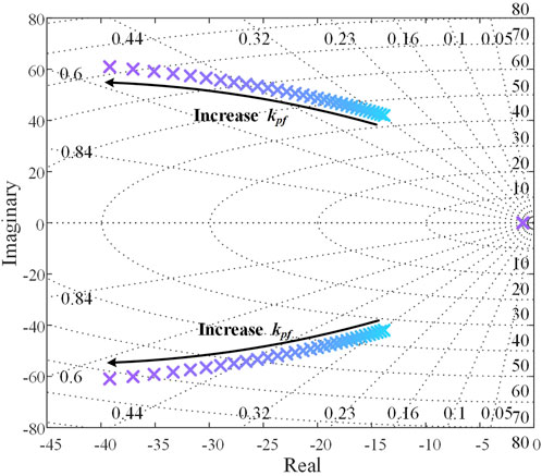
Figure 5. Root locus plot of the variation in the kpf parameter.
As shown in Figure 4, when ki is gradually increased, the imaginary part of the eigenvalue corresponding to the LFO mode remains nearly unchanged, while the real part decreases significantly. This indicates that for a given disturbance, increasing ki has little effect on the oscillation frequency but noticeably extends the duration of oscillations. Moreover, if ki becomes too large, the eigenvalue may cross the imaginary axis into the right-half plane, potentially causing system instability.
In contrast, as shown in Figure 5, with the gradual increase of kpf, both the real and imaginary parts of the eigenvalue corresponding to the LFO mode increase, leading to an enhanced damping ratio. This indicates that under a disturbance, increasing kpf raises the oscillation frequency while significantly reducing the oscillation duration.
3 Identification of negative damping components and strategies for enhancing damping torque
3.1 Torque components in DC-GFM systems
As shown in the analysis of Section 2, an excessively large ki or a too-small kpf can compromise system stability under DC-GFM control. Although tuning these parameters can improve the damping of LFO mode, they often affect other aspects of system performance—for example, a small ki may result in slow DC voltage regulation. An effective approach is to introduce an additional control loop to the existing control structure, providing the system with extra degrees of freedom. However, although the root locus-based parameters analysis can comprehensively reveal the evolution of system poles, it heavily relies on model parameters and falls short of uncovering the underlying mechanism of negative damping, thus making the design of supplementary control loops more challenging.
The damping torque method, based on classical control theory and the decomposition of the torque acting on the motion of generator rotor, quantifies the damping capability of synchronous generators. It is widely used in LFO risk assessment in traditional power systems. It provides clear physical insight into the occurrence of weak or negative damping modes, thereby guiding control design for oscillation suppression. Based on this, the damping torque method is employed in this paper to analyze the sources of negative damping in DC-GFM systems. In high-voltage grids, the grid impedance is primarily inductive, resulting in a decoupling of active and reactive power. Under this condition, the active power can be expressed by the power flow equation as follows:
Here, δ represents the phase angle difference between the converter output voltage and the grid voltage. By linearizing Equation 12, we can obtain:
Here, Ks denotes the power synchronization coefficient of the converter, which reflects the power transfer limit of the DC-GFM system. Accordingly, by combining Equations 3, 8, 9 and 13, the power–frequency transfer function block diagram of the system is shown in Figure 6.
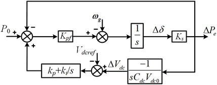
Figure 6. The block diagram of power-frequency transfer function.
When the reference values remain unchanged, the power angle dynamics of the DC-GFM system can be derived from Figure 6 as follows:
Multiplying Equation 14 on both sides by the Laplace operator s leads to:
According to the Phillips model, the power angle dynamics of a synchronous generator can be described as follows (Du and Wang, 2015):
Here, the term D/M, which is associated with frequency, represents the damping torque that affects the ability of system to dampen the LFO. Its physical meaning is clear: it is a force (torque) proportional to velocity (angular velocity), acting as a resistive force (torque) against motion (angular displacement), thereby providing damping. The term ω0K1/M, which relates to the power angle, represents the synchronizing torque that determines the ability of units to maintain synchronism. It primarily influences the oscillation frequency of the output power [19]. Therefore, by comparing Equations 15, 16, it can be observed that Tᴅ is the key factor determining the damping capability of LFOs in DC-GFM systems. When a LFO mode with frequency ωr exists in the system, setting s = jωr yields Tᴅ as:
Figure 7 shows the torque diagram of the DC-GFM system, where TDVC represents the equivalent torque generated by the DC voltage control loop. It can be seen that TD1, formed by component kpfKs, provides positive damping torque to the system, while TD2, involving the ki parameter, introduces negative damping torque. When the system damping is positive, an increase in the ki parameter and a decrease in kpf will gradually reduce the damping of the LFO mode, making the oscillations more pronounced. Therefore, as discussed in Section 2, increasing the ki parameter leads to a decrease in the real part of the LFO mode, while increasing kpf results in an increase in the real part. Meanwhile, in Equation 15, Ts primarily influences the oscillation frequency of the DC-GFM system. As kp and kpf increase, Ts also increases, leading to a higher oscillation frequency. Therefore, in Section 2, as the kp and kpf parameters increase, the imaginary part of the LFO mode gradually increases.
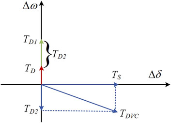
Figure 7. Torque schematic in a DC-GFM system.
3.2 Stability analysis of multi-unit system
As shown in Figure 8, n DC-GFM units operate in parallel, where the output power of GFM_i (i = 1, 2, …, n) is denoted by Pi. The power-frequency transfer relationship at the point of common coupling (PCC) for each GFM_i is given by:
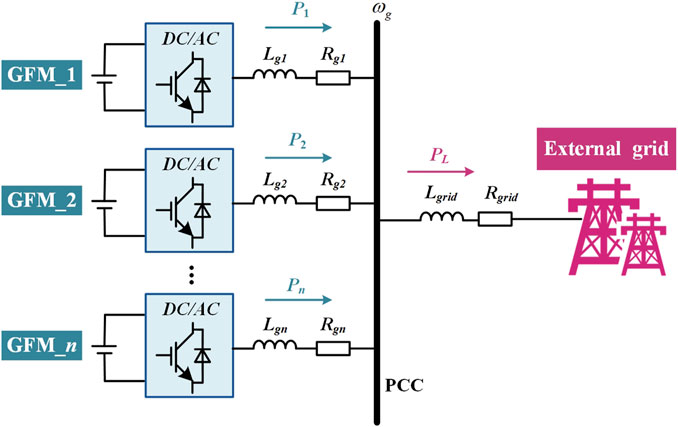
Figure 8. Schematic diagram of a multi-unit parallel system.
For simplicity, the analysis begins with the case of n = 2. When a power disturbance PL occurs on the grid side, the power balance at the PCC can be expressed as Equation 19:
Therefore, the power–frequency relationship at the PCC can be derived as Equation 23:
Equation 20 can be interpreted as the closed-loop transfer function of a negative feedback system, as shown in Figure 9, where the feedforward gain is G2(s)−1 and the feedback gain is G1(s). Therefore, G1(s)/G2(s) represents the open-loop transfer function of the system. According to the Nyquist stability criterion, the system shown in Figure 9 remains stable as long as the condition in Equation 21 is satisfied, ensuring a positive phase margin.
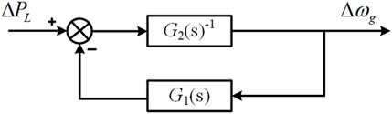
Figure 9. Equivalent negative feedback system of the power–frequency relationship at the PCC.
A sufficient condition for Equation 21 to hold is:
Based on Figure 6 and Equation 18, the expression for Gi (jωr) can be derived as follows:
Therefore, when Equation 24 is satisfied, Equation 22 holds, indicating that the system shown in Figure 9 is stable.
By comparing Equations 17, 24, it can be concluded that the parallel system remains stable when both GFM converters exhibit positive damping torque. This analysis is then extended to the case of multiple DC-GFM units operating in parallel. Consider the jth inverter as a separate subsystem, while treating the remaining inverters as another subsystem. Based on the power balance relationship at the PCC shown in Figure 8, we can derive Equation 25:
Similarly, the power–frequency relationship at the PCC can be expressed as:
Equation 26 can also be viewed as the closed-loop transfer function of a negative feedback system. According to our earlier findings, Equation 22 is satisfied when each GFM converter contributes a positive damping torque. Hence, by applying the rules of complex addition, we obtain:
Since the real part of Gj (jωr) is also positive, it follows that:
Equation 28 indicates that the equivalent negative feedback system described by Equation 26 maintains a positive phase margin at all times. Therefore, when n DC-GFM units operate in parallel, the system remains stable as long as each GFM converter provides positive damping torque. It is worth noting that Equations 27, 28 hold without imposing any constraints on the parameters of the DC-GFM converters. In other words, a multi-converter DC-GFM system with non-identical parameters remains stable as long as each DC-GFM provides positive damping torque.
3.3 Damping enhancement strategy
As demonstrated in Sections 3.1 and 3.2, whether considering a single DC-GFM system or a system composed of multiple DC-GFMs, system stability fundamentally depends on ensuring that the damping torque of each DC-GFM remains positive. However, the integral gain ki of the DC voltage control loop introduces negative damping torque into the system, which may lead to instability. Therefore, an additional damping control strategy is required to enhance system stability. As shown in Figure 10, the introduction of negative damping torque by the ki parameter arises from the −180° phase lag introduced by two successive integration stages in the power-to-frequency feedback path. Therefore, this paper proposes the use of a lead-lag compensator to inject additional damping torque through power feedback, thereby counteracting the negative damping caused by the DC voltage control loop, as illustrated in Figure 10. The transfer function of the lead-lag compensator, Gp, is given by Equation 29:
where, T1 = 10, T2 = 1, and T1 and T2 denote the lead and lag time constants of the lead-lag compensator, respectively. When T1 > T2, the phase of Gp is positive. As a result, the power feedback introduces an additional torque into the system, which acts as a positive damping torque that compensates for the negative damping torque caused by the ki parameter in the DC voltage control loop.
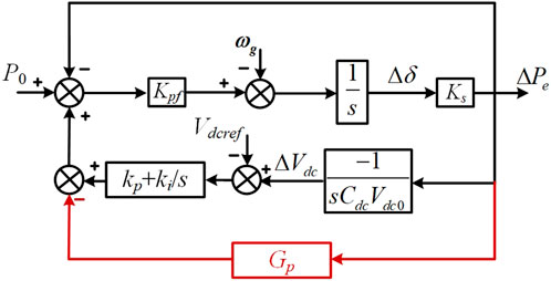
Figure 10. Damping enhancement strategy.
4 Experimental verification
To validate the accuracy of the parameter analysis and the effectiveness of the proposed damping enhancement strategy, a DC-GFM system shown in Figure 1 was developed. The system parameters are listed in Table 1.
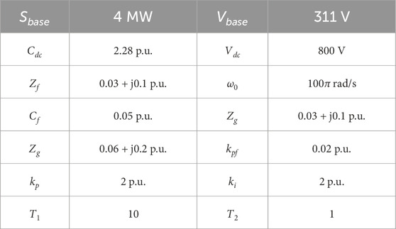
Table 1. System parameters.
4.1 Validation of parameter influence
As shown in Figure 11, the power waveforms under different proportional gains kp of the DC voltage control loop are presented for a 0.4 MW load disturbance occurring at 8 s. It can be observed that the oscillation frequency increases with larger kp values. However, the DC-GFM system reaches steady state at approximately 8.4 s across all kp settings, indicating that kp has little impact on the oscillation duration. This phenomenon has been explained in Sections 2 and 3. It is primarily due to the fact that kp affects the synchronizing torque of the DC-GFM system, which is reflected in the root locus as a change mainly in the imaginary part of the LFO mode.
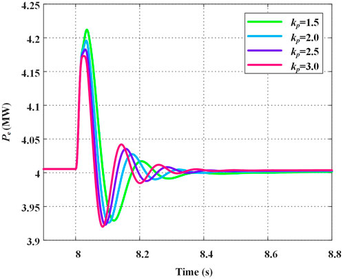
Figure 11. Power waveforms under different kp parameter values.
As shown in Figure 12, when a 0.4 MW load disturbance occurs at 8 s, the power waveforms under different integral gains ki of the DC voltage control loop are presented. It can be observed that increasing ki does not significantly affect the oscillation frequency of the DC-GFM system, but it does lead to a noticeable increase in oscillation amplitude, thereby requiring a longer time to reach steady state. Similarly, the influence of the ki parameter can be explained based on the analysis presented in Sections 2 and 3. As ki increases, it introduces negative damping torque into the system, causing the real part of the LFO mode to gradually decrease. This leads to a reduction in system damping and results in more pronounced oscillations.
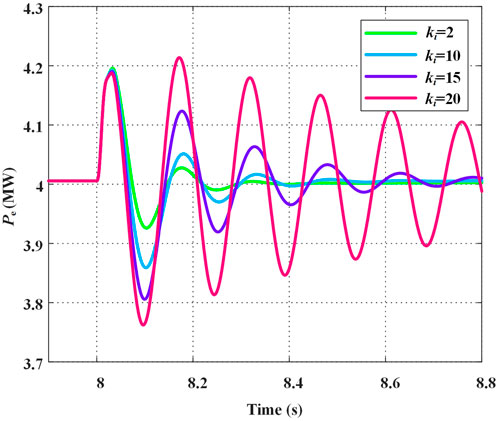
Figure 12. Power waveforms under different ki parameter values.
Figure 13 shows the power profiles under a 0.4 MW load disturbance occurring at 8 s, with different proportional gains kpf in the power control loop. It can be observed that as kpf increases, the oscillation frequency of the DC-GFM converter rises while the amplitude decreases, indicating that a higher kpf helps the converter stabilize more quickly. As indicated by the analysis of Equation 15, this behavior arises because the kpf parameter influences both the damping torque and the synchronizing torque of the system. When the total system damping is positive, increasing kpf enhances both torque components. As a result, the real and imaginary parts of the LFO mode increase, leading to a higher oscillation frequency and faster decay of oscillations.
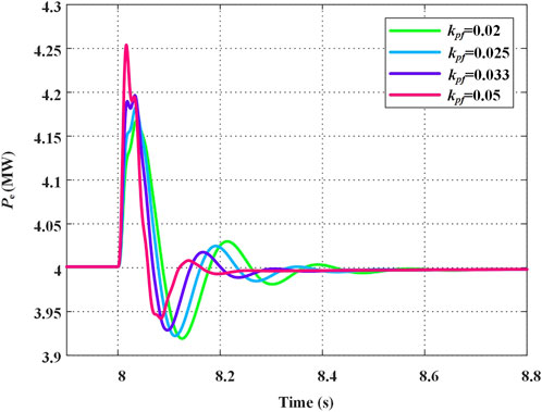
Figure 13. Power waveforms under different kpf parameter values.
4.2 Validation of the proposed damping enhancement strategy
To validate the effectiveness of the proposed damping enhancement strategy, compare the dynamic performance of the DC-GFM converter under identical disturbances using three approaches: conventional DC-GFM control, the damping method based on equivalent DC resistance (DMEDR) from reference (Ai et al., 2024), and the strategy proposed in this paper. Figures 14, 15 presents the power response waveforms with different control methods during a 0.4 MW load disturbance at 8 s. In this case, the parameter ki is set to 30 p. u.
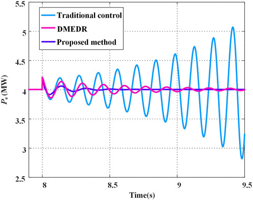
Figure 14. Power waveforms under different control strategies.
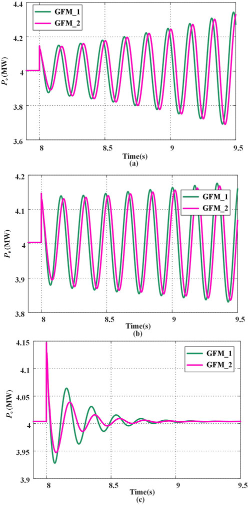
Figure 15. Power response of the system with two parallel DC-GFMs. (a) Without proposed damping enhancement strategy; (b) with the DMEDR; (c) with proposed damping enhancement strategy in this paper.
As shown in Figure 14, without any additional damping control, the DC-GFM converter diverges following the disturbance. In contrast, when applying the DMEDR from reference (Ai et al., 2024) and the strategy proposed in this paper, the converter returns to steady state after a period of oscillation. When the DMEDR from reference (Ai et al., 2024) is applied, the DC-GFM converter requires a relatively long period of oscillation to reach steady state. In contrast, the strategy proposed in this paper enables the system to return to steady state within just two or three oscillation cycles. This demonstrates that the proposed method provides stronger low-frequency damping for single DC-GFM converter systems.
Figure 15 shows the power waveforms during parallel operation of two DC-GFM units. GFM_1 has a ki value of 40 p. u., while GFM_2 has a ki value of 10 p. u. As illustrated in the Figure 12, the system remains stable when only GFM_2 is connected to the grid. However, as shown in Figure 15a, when the proposed damping enhancement strategy is not applied, the power outputs of both units begin to oscillate and gradually diverge after GFM_1 and GFM_2 are connected in parallel. The instability arises because the excessive negative damping torque generated by the high ki value in GFM_1 drives the total system damping below zero. Therefore, even though GFM_2 itself provides positive damping torque, it still becomes unstable due to the gradual divergence of the electrical quantities of system. As shown in Figure 15b, after applying the DMEDR from reference (Ai et al., 2024), the equivalent resistance on the DC side provides some damping, which slows down the power divergence of GFM_1 and GFM_2. However, the system still gradually becomes unstable. In contrast, as shown in Figure 15c, when the proposed damping enhancement strategy is applied to both units, the output power of each unit reaches steady state around 9 s after experiencing a short oscillation. This demonstrates that the proposed strategy is also effective in suppressing oscillations in multi-unit systems.
5 Limitations and future research
This paper primarily discusses LFO in GFM systems following the introduction of the DC voltage control loop. Using the damping torque method, it analyzes the impact mechanisms of control parameters in both the DC voltage control loop and active power control loop of DC-GFM within high-voltage grids, examines the stability conditions of multiple DC-GFM parallel systems, and proposes a damping enhancement strategy. However, DC-GFM converters also include multiple cascaded control loops, such as reactive power control loops and voltage-current control loops (Yu et al., 2021). In high-voltage grids, due to the low R/X ratio, active and reactive power are approximately decoupled, and since the voltage-current control loop typically have bandwidths above several tens Hz, the reactive power and voltage-current control loops have minimal impact on the frequency dynamics of DC-GFM converters (Wen et al., 2021). However, in low-voltage grids with a low R/X ratio and in large-capacity stations, the active power control loop can become coupled with the reactive power and voltage-current control loops (Qu et al., 2021; Li C. et al., 2022), making the torque composition of DC-GFM converters highly complex. In this situation, the effects of parameters in the DC voltage control loop and active power control loop might alter. Therefore, further research is needed to analyze the parameter effects and stability of DC-GFM converters under different scenarios, considering the coupling among multiple control loops.
Moreover, the multi-unit stability analysis and damping enhancement strategies discussed in this paper primarily focus on scenarios where DC-GFM converters operate in parallel. With the increasing integration of renewable energy, power systems may include various types of grid-connected devices, such as grid-following converters (Rosso et al., 2020), synchronous generators, and power-synchronization-based GFM converters (Zhang et al., 2016). The dynamics of these devices differ significantly from those of DC-GFM converters. When they are located close to each other in the grid, interactions may occur that alter the LFO characteristics of the DC-GFM converters. Future research is needed to further investigate LFO issues arising from dynamic interactions among different devices.
6 Conclusion
To address the issue of LFOs in GFM converters based on DC capacitor synchronization, this paper establishes a state-space model of the converter and analyzes how the parameters of the DC voltage control loop and power control loop affect the LFO mode of system. The results show that increasing the proportional gain of the DC voltage control loop raises the oscillation frequency, while increasing the integral gain extends the duration of oscillations. In contrast, increasing the proportional gain of the power control loop leads to a higher oscillation frequency and a shorter oscillation duration. Subsequently, the damping torque method was employed to analyze the components contributing to damping torque and synchronizing torque in GFM converters, providing a clear explanation of the root causes of negative damping and the underlying mechanisms of parameter influence. The stability conditions of a multi-DC-GFM parallel system were analyzed, and the results indicate that the system remains stable as long as each DC-GFM converter pro-vides a positive damping torque. On this basis, a damping enhancement strategy was proposed using a lead-lag compensator. Finally, simulation results were used to validate both the parameter analysis and the effectiveness of the proposed control strategy.
Data availability statement
The raw data supporting the conclusions of this article will be made available by the authors, without undue reservation.
Author contributions
WK: Writing – original draft, Validation, Methodology. YZ: Writing – review and editing, Validation. JL: Investigation, Writing – review and editing, Conceptualization, Data curation. JW: Visualization, Writing – review and editing, Conceptualization. JX: Project administration, Writing – review and editing, Formal Analysis, Resources. LL: Software, Writing – review and editing, Supervision.
Funding
The author(s) declare that financial support was received for the research and/or publication of this article. This work was supported in part by the Science and Technology Project of State Grid Xizang Electric Power Co., Ltd. (523101230003).
Conflict of interest
Author YZ was employed by State Grid Lasa Power Supply Company.
Author JW was employed by State Grid Xizang Electric Power Company Limited.
The remaining authors declare that the research was conducted in the absence of any commercial or financial relationships that could be construed as a potential conflict of interest.
The authors declare that this study received funding from State Grid Xizang Electric Power Co., Ltd. The funder had the following involvement in the study: collection and interpretation of data.
Generative AI statement
The author(s) declare that no Generative AI was used in the creation of this manuscript.
Publisher’s note
All claims expressed in this article are solely those of the authors and do not necessarily represent those of their affiliated organizations, or those of the publisher, the editors and the reviewers. Any product that may be evaluated in this article, or claim that may be made by its manufacturer, is not guaranteed or endorsed by the publisher.
References
Ai, C., Li, Y., Zhao, Z., Gu, Y., and Liu, J. (2024). An extension of grid-forming: a frequency-following voltage-forming inverter. IEEE Trans. Power Electron 39 (10), 12118–12123. doi:10.1109/tpel.2024.3387705
Arco, S. D., and Suul, J. A. (2014). Equivalence of virtual synchronous machines and frequency-droops for converter-based MicroGrids. IEEE Trans. Smart Grid 5 (1), 394–395. doi:10.1109/tsg.2013.2288000
Arghir, C., and Dörfler, F. (2020). The electronic realization of synchronous machines: model matching, angle tracking, and energy shaping techniques. IEEE Trans. Power Electron 35 (4), 4398–4410. doi:10.1109/tpel.2019.2939710
Commission, A. E. M. (2019). Mechanisms to enhance resilience in the power system-review of the South Australian Black system event.
Dhople, S. V., Johnson, B. B., and Hamadeh, A. O. (2013). “Virtual oscillator control for voltage source inverters,” in 51st IEEE annual allerton conference on communication, control, and computing; 2013 Oct 02-04. New York: IEEE.
J. Driesen, and K. Visscher (2008). “Virtual synchronous generators,” 2008 IEEE power and energy society general meeting - conversion and delivery of electrical energy in the 21st century.
Du, W., and Wang, H. (2015). Analysis theory and method of damping torque for low-frequency power oscillation in power systems. China: Science Press.
Eso, N. G. (2019). Technical report on the events of 9 August 2019. Warwick. China: National Grid ESO.
Guerrero, J. M., Vasquez, J. C., Matas, J., Vicuna, L., and Castilla, M. (2011). Hierarchical control of droop-controlled AC and DC microgrids—A general approach toward standardization. IEEE Trans. Ind. Electron 58 (1), 158–172. doi:10.1109/tie.2010.2066534
Guo, J., Chen, Y., Wang, L., Wu, W., Wang, X., Shuai, Z., et al. (2021). Impedance analysis and stabilization of virtual synchronous generators with different DC-Link voltage controllers under weak grid. IEEE Trans. Power Electron 36 (10), 11397–11408. doi:10.1109/tpel.2021.3070038
Hu, P., Jiang, K., Ji, X., Cai, Y., Wang, B., Liu, D., et al. (2023). A novel grid-forming strategy for self-synchronous PMSG under nearly 100% renewable electricity. Energies 16 (18), 6648. doi:10.3390/en16186648
Hui Liu, S. Y., Sun, D., Wu, L. L., Li, Y. H., and Wang, X. (2024). An overview of control technologies and principles for grid-forming converters. Proc. CSEE. doi:10.13334/j.0258-8013.pcsee.232479
Ji, X., Liu, D., Jiang, K., Zhang, Z., and Yang, Y. (2024). Small-signal stability of hybrid inverters with grid-following and grid-forming controls. Energies 17 (7), 1644. doi:10.3390/en17071644
Johnson, B. B., Dhople, S. V., Hamadeh, A. O., and Krein, P. T. (2014). Synchronization of parallel single-phase inverters with virtual oscillator control. IEEE Trans Power Electron 29 (11), 6124–6138. doi:10.1109/tpel.2013.2296292
T. Jouini, C. Arghir, and F. Dörfler (2016). “Grid-friendly matching of synchronous machines by tapping into the DC storage,” 6th IFAC workshop on distributed estimation and control in networked systems (NECSYS); 2016 sep 08-09; Tokyo, JAPAN (AMSTERDAM: Elsevier).
Li, C., Yang, Y., Mijatovic, N., and Dragicevic, T. (2022c). Frequency stability assessment of grid-forming VSG in framework of MPME with feedforward decoupling control strategy. IEEE Trans Ind Electron 69 (7), 6903–6913. doi:10.1109/tie.2021.3099236
Li, J., Ali, M., Fletcher, J. E., and Nurdin, H. I. (2022b). Modeling and analysis of multiple inverters with dual-loop-based virtual oscillator control. IEEE J Emerging Sel Top Power Electron 10 (4), 3963–3974. doi:10.1109/jestpe.2021.3129083
Li, M., Wang, Y., Hu, W., Shu, S., Yu, P., Zhang, Z., et al. (2022a). Unified modeling and analysis of dynamic power coupling for grid-forming converters. IEEE Trans Power Electron 37 (2), 2321–2337. doi:10.1109/tpel.2021.3107329
Liu, J., Miura, Y., and Ise, T. (2016). Comparison of dynamic characteristics between virtual synchronous generator and droop control in inverter-based distributed generators. IEEE Trans Power Electron 31 (5), 3600–3611. doi:10.1109/tpel.2015.2465852
Liu, Y., Su, J., Sun, D., Liu, Y., and He, Y. (2025). Comparative study on the stability of grid-forming converters under virtual synchronization and matching control. Electric Power Science and Engineering 41.
Qu, Z., Peng, J. C. H., Yang, H., and Srinivasan, D. (2021). Modeling and analysis of inner controls effects on damping and synchronizing torque components in VSG-controlled converter. IEEE Trans Energy Convers 36 (1), 488–499. doi:10.1109/tec.2020.3010049
Rahman, K., Hashimoto, J., Orihara, D., Ustun, T. S., Otani, K., Kikusato, H., et al. (2024). Reviewing control paradigms and emerging trends of grid-forming inverters—a comparative study. Energies 17 (10), 2400. doi:10.3390/en17102400
Rosso, R., Engelken, S., and Liserre, M. (2020). Robust stability investigation of the interactions among grid-forming and grid-following converters. IEEE J Emerging Sel Top Power Electron 8 (2), 991–1003. doi:10.1109/jestpe.2019.2951091
Su, Z., Yang, G., and Yao, L. (2025). Transient frequency modeling and characteristic analysis of virtual synchronous generator. Energies 18 (5), 1098. doi:10.3390/en18051098
Tayab, U. B., Roslan, M. A. B., Hwai, L. J., and Kashif, M. (2017). A review of droop control techniques for microgrid. Renewable Sustainable Energy Rev. 76, 717–727. doi:10.1016/j.rser.2017.03.028
Wang, W., Jiang, L., Cao, Y., and Li, Y. (2020). A parameter alternating VSG controller of VSC-MTDC systems for low frequency oscillation damping. IEEE Trans Power Syst 35 (6), 4609–4621. doi:10.1109/tpwrs.2020.2997859
Wang, Y., Chen, S., Yang, M. L., Liao, P., Xiao, X. Y., Xie, X. R., et al. (2025). Low-frequency oscillation in power grids with virtual synchronous generators: a comprehensive review. Renew Sust Energ Rev. 207, 114921. doi:10.1016/j.rser.2024.114921
Wen, T., Zhu, D., Zou, X., Jiang, B., Peng, L., and Kang, Y. (2021). Power coupling mechanism analysis and improved decoupling control for virtual synchronous generator. IEEE Trans Power Electron 36 (3), 3028–3041. doi:10.1109/tpel.2020.3017254
Yu, Y., Tinajero, G. D. A., Chaudhary, S. K., Xu, L., and Bakar, NNBA, Guerrero, J. M., et al. (2021). “A comparison of fixed-parameter active-power-oscillation damping solutions for virtual synchronous generators,” Iecon 2021 – 47Th annual conference of the (IEEE Industrial Electronics Society).
Zhang, W., Cantarellas, A. M., Rocabert, J., Luna, A., and Rodriguez, P. (2016). Synchronous power controller with flexible droop characteristics for renewable power generation systems. IEEE Trans Sustainable Energy 7 (4), 1572–1582. doi:10.1109/tste.2016.2565059
Zhao, L., Jin, Z., and Wang, X. (2023a). Small-signal synchronization stability of grid-forming converters with regulated DC-Link dynamics. IEEE Trans Ind Electron 70 (12), 12399–12409. doi:10.1109/tie.2023.3234147
Zhao, L., Wang, X., and Jin, Z. (2023b). Impedance-based dynamics analysis for DC-Link voltage-synchronized voltage-source converters. IEEE Trans Power Electron 38 (9), 10829–10844. doi:10.1109/tpel.2023.3288750
Keywords: grid-forming converter, DC-voltage controller, low-frequency oscillation, damping torque method, lead-lag compensator
Citation: Kong W, Zhou Y, Li J, Wu J, Xia J and Lei L (2025) Analysis of low-frequency oscillation characteristics and damping enhancement strategy for grid-forming PV with DC-voltage controller. Front. Energy Res. 13:1623678. doi: 10.3389/fenrg.2025.1623678
Received: 06 May 2025; Accepted: 15 July 2025;
Published: 28 July 2025.
Edited by:
Kenneth E. Okedu, Melbourne Institute of Technology, AustraliaReviewed by:
Kavita Singh, Affiliated to J C Bose University, IndiaChaoran Zhuo, Xi’an University of Technology, China
Copyright © 2025 Kong, Zhou, Li, Wu, Xia and Lei. This is an open-access article distributed under the terms of the Creative Commons Attribution License (CC BY). The use, distribution or reproduction in other forums is permitted, provided the original author(s) and the copyright owner(s) are credited and that the original publication in this journal is cited, in accordance with accepted academic practice. No use, distribution or reproduction is permitted which does not comply with these terms.
*Correspondence: Weikang Kong, a29uZ3drMjAyNUAxNjMuY29t