 Feng Zeng
 Yang Gao
 Fujiang Chen
 Qingqing He
 Zhihao He
- 1School of Emergency Management, Xihua University, Chengdu, China
- 2Key Laboratory of Geohazard Prevention of Hilly Mountains, Ministry of Natural Resources, Fuzhou, China
- 3Fujian Key Laboratory of Geohazard Prevention, Fuzhou, China
- 4State Key Laboratory of Geohazard Prevention and Geoenvironment Protection, Chengdu University of Technology, Chengdu, China
The shield machine tunnelling along the curve section causes more disturbance to the surrounding environment than the straight section. Pile foundation is the most commonly used foundation form in high-rise buildings, and high-rise buildings have extremely high requirements for controlling non-uniform deformation. Therefore, it is necessary to study the surface settlement and the deformation law of pile foundations caused by shield machine tunnelling along the curve section. Considering the shield machine tunnelling factors along the curve section and the coupling effect of piles and soil, the analytical calculation formula of the ground settlement and the pile foundation deformation caused by the shield machine tunnelling along the curve section is deduced. According to the actual project situation, a finite difference model (FDM) is constructed, and the correctness of the FDM and analytical prediction formula is verified by comparing the on-site monitoring data. The research shows that the error among the FDM results, the analytical prediction results, and the on-site monitoring data are small, and the surface settlement and pile foundation deformation meet the construction control standards. The friction resistance of the shield shell, the integrative gap at the shield tail (IGST), and the over-cutting gap (OG) are the main factors leading to the surface settlement. However, the shield shell friction and OG are the main reasons leading to the inner settlement of the curve section being more prominent than the outer side. The difference in the pile foundation settlement on both sides of the curve section is slight, the maximum settlement difference rate is 1.8%, and the maximum horizontal deformation rate of the pile foundation on the inner and outer sides is 9.2%, which shows that the horizontal deformation of the pile foundation is more sensitive to the asymmetrically distributed construction factors.
Introduction
The shield method has the characteristics of less disturbance of excavation and high construction efficiency. Underground lines such as urban subways and municipal pile lines are usually constructed by the shield method (Xie and Tang, 2017; Chen et al., 2018). The extremely limited underground space in the city makes the construction environment of the shield tunnel very complicated. Living pile lines, hidden buildings and building foundations are intricately distributed. Shield tunnelling will disturb these existing structures, resulting in settlement, deformation and even cracking of existing structures, posing a significant threat to the safe use of existing structures (Li et al., 2019; Huang et al., 2020; Lin et al., 2020; Liu et al., 2020; Miao et al., 2020).
The pile foundation is the most commonly used foundation for high-rise buildings. Compared with other types of foundations, the shield machine is more likely to disturb the soil around the pile foundation, and cause the settlement of the pile foundation, resulting in quicksand and piping in the foundation pit, thus affecting the surrounding environment. Numerous scholars have studied the pile foundation settlement caused by shield tunnelling through analytical analysis, laboratory tests and numerical simulations. Hu et al. (2021) proposed a simplified calculation method to analyse the impact of shield excavation on adjacent pile foundations. A two-stage method of modified Peck formula and Winkler elastic foundation model was used to investigate the additional displacement and internal force of pile; Basile (2014) proposed an efficient analysis method is presented for estimating the effects induced by tunnelling on existing pile foundations; Lee and Jacobsz (2006) studied the effects of tunnelling on an existing pile constructed in weathered residual soil and rock by carrying out three-dimensional parametric elasto-plastic numerical analyses. Franza et al. (2017) present an elastic study of tunnel-pile-structure interaction through Winkler-based Two-Stage Analysis Methods (TSAMs), focussing on structural displacements resulting from tunnel excavation beneath piled frames or simple equivalent beams; Jongpradist et al. (2013) investigate the influences of tunnel excavation on existing loaded piles by three-dimensional elasto-plastic numerical analyses; Mroueh and Shahrour (2002) used an elastoplastic three-dimensional finite element modelling to analysis of the impact of the construction of urban tunnels on adjacent pile foundations. He et al. (2013) used the Φ520 mm earth pressure balance (EPB) model shield machine to investigate the impact of shield tunnelling on the existing pile foundation deformation and internal forces; Min et al. (2011) used a three-dimensional finite element simulation and centrifuge test to investigate the effects of tunnel construction on nearby pile foundation. Miao et al. (2022) used a geotechnical centrifugal test to reveal the failure mode and deformation mechanism under the action of water level fluctuation and rainfall. Zhang et al. (2021) have analysed the relationship between groundwater quality and human health risks. Soomro et al. (2021) used an advanced hypoplastic soil model to investigate the response of an existing vertically loaded 2 × 2 pile group in a lateral direction due to the advancement of twin stacked tunnels in dry sand. However, few studies focus on shield machine tunnelling along the curve section. In actual construction, it is more common for the shield machine tunnelling along the curve section than the straight section. According to Deng’s research (Deng et al., 2022), the construction factors of shield machine tunnelling along the curve section are more complicated than that of the straight section, which will cause more disturbance to the surrounding environment. Therefore, it is necessary to study the deformation law of pile foundations caused by shield machine tunnelling along the curve section and to propose the analytical calculation formula of pile foundation settlement.
The main contents of this study include: In section “Soil deformation caused by tunnelling construction factor,” the analytical calculation formula of soil deformation caused by the additional thrust, the shield shell friction and the additional grouting pressure are derived. Then, the analytical calculation formula of soil deformation caused by OG and IGST is derived based on the mirror image method and the Loganathan formula, respectively. In section “Calculation of pile foundation deformation,” the pile foundation is regarded as a Euler-Bernoulli beam placed on the elastic foundation beam. The calculation formula of the pile deformation is deduced considering the coupling effect of the pile-soil displacement. In section “Numerical calculation model,” based on actual engineering cases, a finite difference model (FDM) calculation model is constructed; then, the analytical formula prediction results, FDM calculation results, and on-site monitoring data are compared to verify the rationality of the analytical calculation formula and FDM. This study can provide an analytical prediction formula for similar projects and predict the construction risk of shield tunnelling in advance.
Soil deformation caused by tunnelling construction factor
Existing studies have pointed out that the additional thrust, the shield shell friction, the additional grouting pressure, and the ground loss are the main factors that disturb the surrounding soil during the shield machine tunnelling process. Different excavation parameters need to be set for the units on the inner and outer sides of the curve section to realise the deflection of the excavation axis when the shield machine tunnelling along the curve section field (Liang et al., 2018; Li and Li, 2021). The thrust of the inner cylinder will be smaller than that of the outer cylinder, and due to the extrusion of the inner soil, the friction of the inner shield will be greater than that of the outer shield. According to the above analysis, this study assumes that the applied load satisfies the following assumptions (Deng et al., 2021): (1) The soil is an isotropic homogeneous body, the calculation area is a linear elastic semi-infinite space, and the effect of soil drainage and consolidation during construction is not considered; (2) q1 and q2 is the additional inner thrust and additional outer thrust, respectively, generally speaking, q2 > q1, that is, the additional thrust on the outside is greater than the additional thrust on the inside. (3) f1 and f2 are the friction of the inner shield shell and outer shield shell, respectively. During the turning process, the inner shield shell receives more soil extrusion, which leads to the additional thrust on the outside being more significant than the additional thrust on the inside. (4) The influence range of the shield tail grouting is the width of the three-ring segment behind the shield tail. According to the above analysis, the load distribution of the shield machine when driving along the curved section is shown in Figure 1.
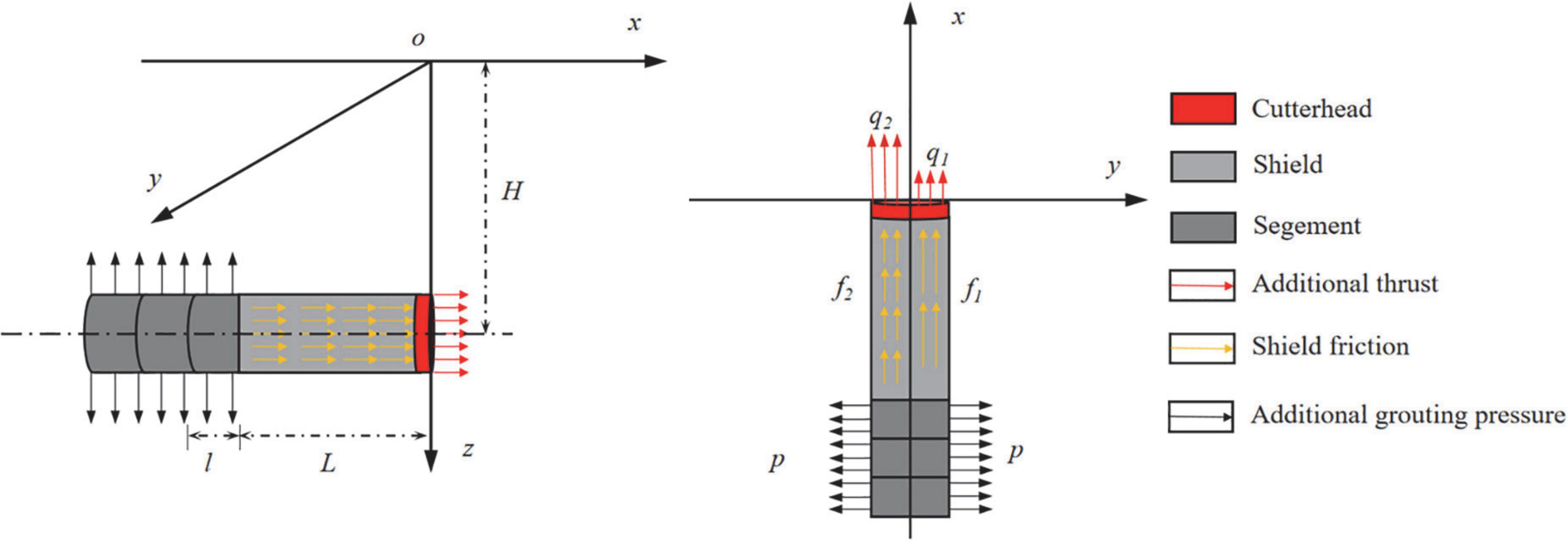
Figure 1. Load distribution of shield machine tunnelling.
The shield machine is squeezed by asymmetric distribution on the inside and outside of the curve section, which will make the shield machine challenging to excavate and reduce its service life of the shield machine. Therefore, given the circumstance that the shield machine is tunnelling along the curved section, the turning of the shield machine is generally realised by setting the asymmetric distribution of the thrust of the oil cylinders on both sides in the weak stratum. In the hard stratum, according to the actual construction situation, it is also necessary to over-cutting of the inner soil. When the shield machine excavates in the straight section, the ground loss mainly comes from the gap caused by the shield tail void. Although the technology of synchronous grouting is becoming increasingly mature, the ground loss caused by the shield tail void is still unavoidable. This part of the formation loss is known as the integrative gap at the shield tail (IGST). In the hard soil layer, the over-cutting of the inner soil will also cause ground loss, and this part of the formation loss is called the over-cutting gap (OG). Figure 2 shows the distribution of ground loss.
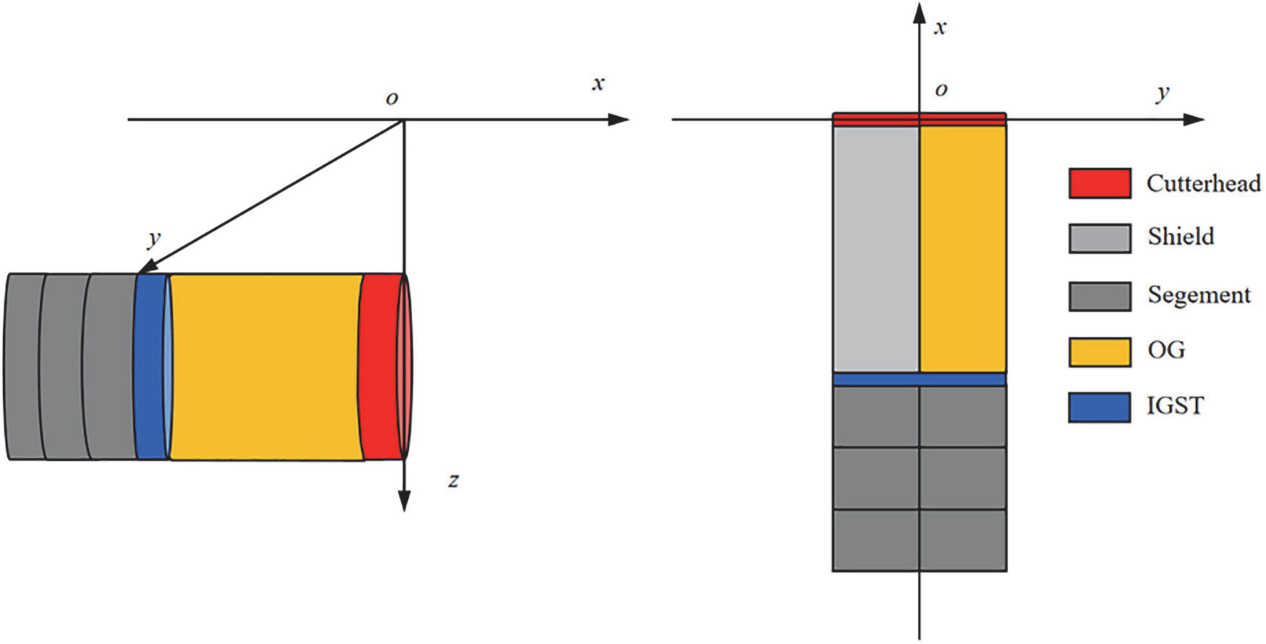
Figure 2. Distribution of ground loss in the curve section.
Computational theory
Mindlin (1936) takes the elastic semi-infinite space body as the research area and derives the settlement calculation formula of any point (x, y, z) in the space caused by the horizontal and vertical loads at a certain point (x0, y0, z0).
The point (x0, y0, z0) under the action of the horizontal load Ph to cause another point of vertical deformation Wz1 and horizontal deformation Wx1, Wy1 calculation formula:
The point (x0, y0, z0) under the action of the vertical load Pv to cause another point of vertical deformation Wv2 and horizontal deformation Wh2 calculation formula:
Where: G is the shear modulus of the soil; μ is the Poisson’s ratio of soil; R1 = [(x-x0)2+(y-y0)2+(z-z0)2]1/2; R2 = [(x-x0)2+(y-y0)2+(z+z0)2]1/2.
In order to simplify the expression of the calculation formula, the formula is simplified as: Wz1 = Wz1(x,y,z,x0,y0,z0,Ph), Wx1 = Wx1(x,y,z,x0,y0,z0,Ph), Wy1 = Wy1(x,y,z,x0,y0,z0,Ph), Wz2 = Wz2(x,y,z,x0,y0,z0,Pv), Wx2(x,y,z,x0,y0,z0,Pv), Wy2(x,y,z,x0,y0,z0,Pv).
Frontal additional thrust
The additional frontal thrust acting on the cutter head can be approximated as a horizontal load. According to the distribution in Figure 1, the coordinates of the centre point of the cutter head are (0, 0, H). Assuming that the additional thrust is evenly distributed on the cutter head, the additional thrust per unit area is dPh = qdA = rqdrdθ. The coordinates of a point (x0, y0, z0) on the cutter head can be expressed as:
Substituting the above formula into Eqs 1–3, the calculation formula of the formation deformation caused by the additional thrust per unit area is:
The above equation has two integral variables, r and θ, respectively. The integral range of r is 0∼R. The inner and outer sides of the cutter head are integrated, and the calculation formula of the formation deformation caused by the additional thrust of the cutter head is calculated as follows:
Shield friction
The action range of the shield shell friction is from the cutter head to the shield tail, assuming that the shield shell friction is evenly distributed on the shield shell. The shield friction can also be regarded as a horizontal acting load. The friction dPh = fRdβds on the shield shell per unit area, the coordinates of any point on the shield shell can be expressed as:
Substituting the above formula into Eqs 1–3, the calculation formula of the formation deformation caused by the shield shell friction per unit area is:
There are two integral variables in the above formula: s and β. The integral interval of s is 0∼L. By integrating both sides of the shield shell, the calculation formula of the formation deformation caused by the friction resistance of the shield shell can be calculated as follows:
Additional grouting pressure
The action range of the additional grouting pressure is the length of the three-ring segment behind the shield tail, and the action direction is the normal outer direction of the segment. The grouting pressure can be decomposed into horizontal action load and vertical action load. The value of the additional grouting pressure per unit area of the segment is dp = pRdβda, the value of the horizontal load is dPh = pRcosβdβda, and the value of the vertical load is dPv = pRsinβdβda. The coordinates of any point on the segment can be expressed as:
Substituting the above formula into Eqs 1–6, the calculation formula of the formation deformation caused by the additional grouting pressure per unit area is:
Two integral variables in the above formula, a and β, are integrated over the entire action area. The integral interval of a is 0∼3l, and the integral interval of β is 0∼2π.
Ground loss
Integrative gap at the shield tail
According to the model proposed by Loganathan (1998) and Lee et al. (1992) deduces the calculation formula of the soil settlement wigstz and horizontal deformation wigstx caused by the clearance of the shield tail.
Where: (x, y, z) is the calculated point coordinate; (x0, y0, H) is the coordinate of the centre point of the cutter head; g is the ground loss parameter, (m).
Over-cutting gap
Festa et al. (2012) proposed the calculation formula of the over-cutting gap amount δ:
Sagaseta (1987) deduced that the settlement change amount of the calculated point is the settlement used by the shear stress and the settlement caused by the volume change. The formation deformation caused by shear stress can be ignored, and only the formation deformation caused by the volume change needs to be considered. The calculation formulas of vertical deformation wzog and horizontal deformation wxog are:
Where: (x1, y1, z1) are the void point coordinates; r1 = [(x-x0)2+(y-y0)2+(z-z0)2]1/2; r2 = [(x-x0)2+(y-y0)2+(z+z0)2]1/2.
The ground loss caused by OG is mainly located in the inner side of the curve section, and this part of the ground loss always exists before the cutter head passes, so the distribution range of the ground loss caused by OG is from the cutter head to the shield tail. The coordinates of the void point can be expressed as:
According to Eqs 27, 28, integrating the over-excavation area, the calculation formula of the formation deformation caused by the OG can be obtained as follows:
To sum up, the calculation formula of formation deformation caused by shield tunnelling along the curve section is:
Calculation of pile foundation deformation
Commonly used elastic foundation beam models include Winkler’s foundation model, Pasternak’s foundation model and Vlasov’s foundation model (Zheng et al., 2021). The two-parameter Pasternak’s foundation model considers the shearing effect of soil based on Winkler’s foundation model foundation beam and contains only two parameters. Therefore, it is often used to calculate the deformation of underground structures.
The governing differential equations of Pasternak’s foundation model can be expressed as:
where w(i) is the deformation of the pile; K is the foundation reaction modulus; Gc is the stiffness of the shear layer; i represents three coordinate directions. The values of K and Gc are shown in Eqs 36, 37.
where Es is the elastic modulus of soil; D is the diameter of the pile; EI is the bending stiffness of the pile; t is the thickness of a shear layer, t is typically considered to be 2.5 times equal to the pile diameter.
Pile-soil coupling equation
Equation 34 is a high-order differential equation. It is difficult to obtain accurate results by conventional calculation methods and the calculation is challenging (Liang et al., 2018; Zhang et al., 2018; Ma et al., 2020). The finite difference method is one of the essential means of solving the high-order differential equation. The pile body is discretised into 2N+5 units and each unit have a length of t, including 2N+1 units within the calculation range and two virtual units on both sides of the calculation range. The pile foundation after discretisation is shown in Figure 3.
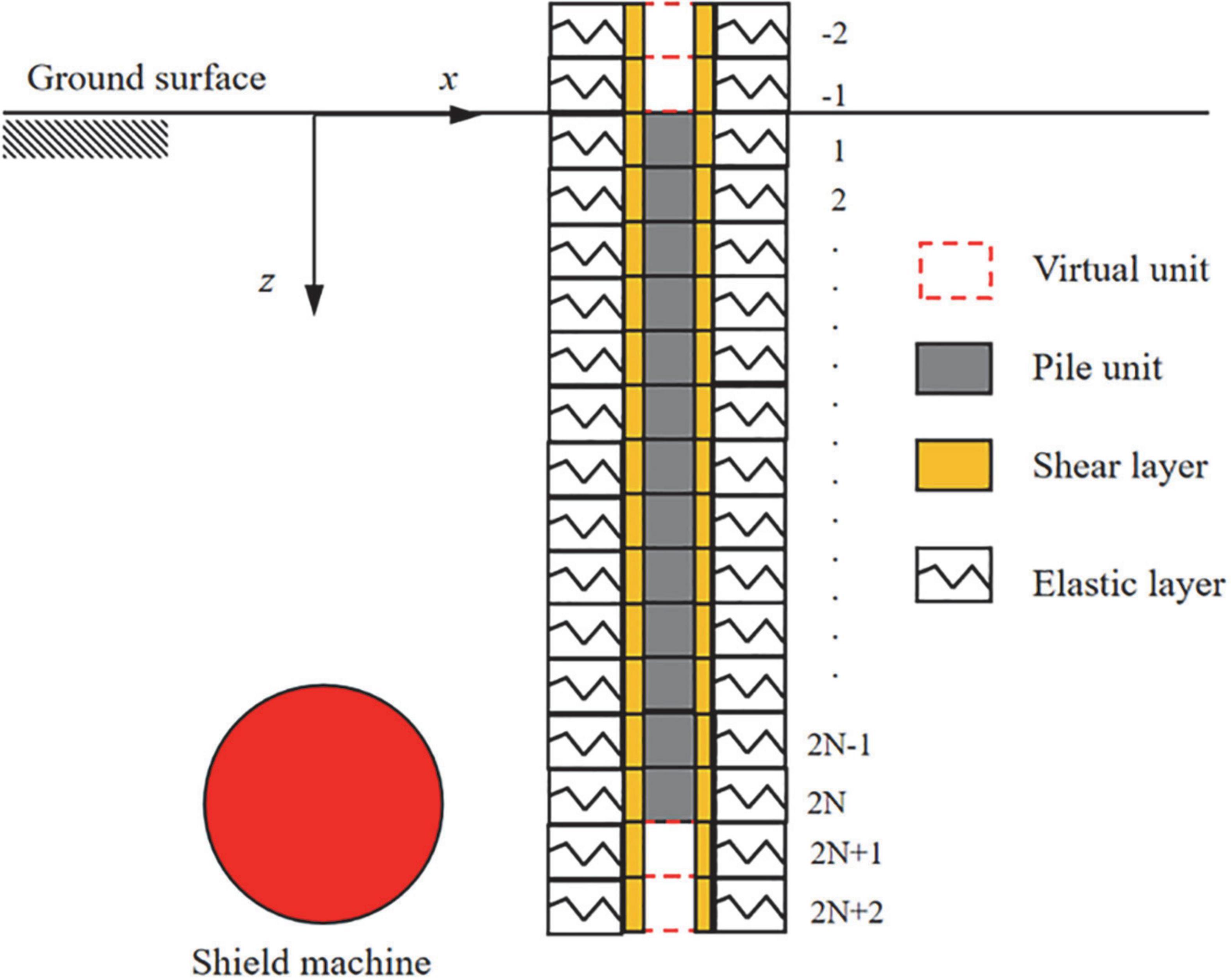
Figure 3. Pile foundation discrete diagram.
According to the central difference rule, higher-order differential equations can be converted to regular equations by the following equation.
Equation 35 is then converted to:
Assuming that the top of the pile foundation and the bottom of the pile end are both free ends, then the bending moment and shear force at both ends of the pile foundation are 0, and the nodes outside the calculation range satisfy:
Convert the corresponding system of equations to a matrix-vector:
Where: [q(z)]2N+1 is the additional load matrix; [k]2N+1 is the soil subgrade coefficient matrix; [G]2N+1 is the shear layer stiffness matrix; [K]2N+1 is the stiffness matrix of the pile body; [wG(z)]2N+1 is the deformation matrix of the pile body.
Deformation formula
According to the above analysis, it is only necessary to determine the stiffness matrix in Eq. 41 and the deformation matrix of the calculation point in the tunnelling process of the shield machine. Then the deformation of the pile can be calculated.
For the deformation stiffness matrices in the x and y directions of the pile foundation:
where kx,i = KDt4/EI, (–2 ≤ i ≤ 2N+2), α = –(4+GcDt2/EI), β = 6+2GcDt2/EI+KDt4/EI.
For the stiffness matrix in the z direction:
where kz,i =−Kt2/Gc, (−2 ≤ i ≤ 2N+2), A =−(2+Kt2/Gc).
Numerical calculation model
Based on constitutive models and failure mechanism of geotechnical materials (Chen et al., 2022; Gao et al., 2022), the numerical method has developed rapidly. It is an attractive tool been widely used in civil engineering. In this paper, finite difference software is used. Based on the solid engineering background, a FDM is constructed to verify the correctness of the theoretical calculation formula.
Research background
The subway project of Line 5 in Changsha City, Hunan Province, China, adopts the shield tunnelling method. The left and right lines of the section are two single-track tunnels. In a specific section of the line, the plane curve radius of the left line is 350 m, and the plane curve radius of the right line is 1800 m. The radius of the tunnel is 6.2 m, and the length of the shield shell is 6.5 m. The tunnel is assembled with C30 segments, and the width of the single ring segment is 1.5 m. The distribution of surrounding buildings is complicated. A high-rise hotel (25 floors, pile foundation, depth 15 m, pile diameter 2.0 m) is only 6 m away from the left subway section. According to the on-site exploration results, the mechanical parameters are shown in Table 1.
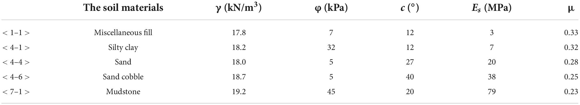
Table 1. Mechanical parameters of soil layer.
Model introduction
The shield machine has the most significant risk of disturbance to the high-rise hotel during the tunnelling process of the curve section. At the same time, the distance between the left line and the pile foundation is the closest, and the distance between the right line and the pile foundation exceeds six times the hole diameter. Therefore, only the left line alone is considered in the model. In order to eliminate the influence of boundary conditions (Nematollahi and Dias, 2019), the size of the model is taken as 100 × 100 × 33 m, and the overall numerical calculation model constructed is shown in Figure 4A. The influence of the distance from the pile group to the tunnel on the pile foundation settlement, the positional relationship between the tunnel and the pile group, and the distribution of the pile group can be analysed as shown in Figure 4B.
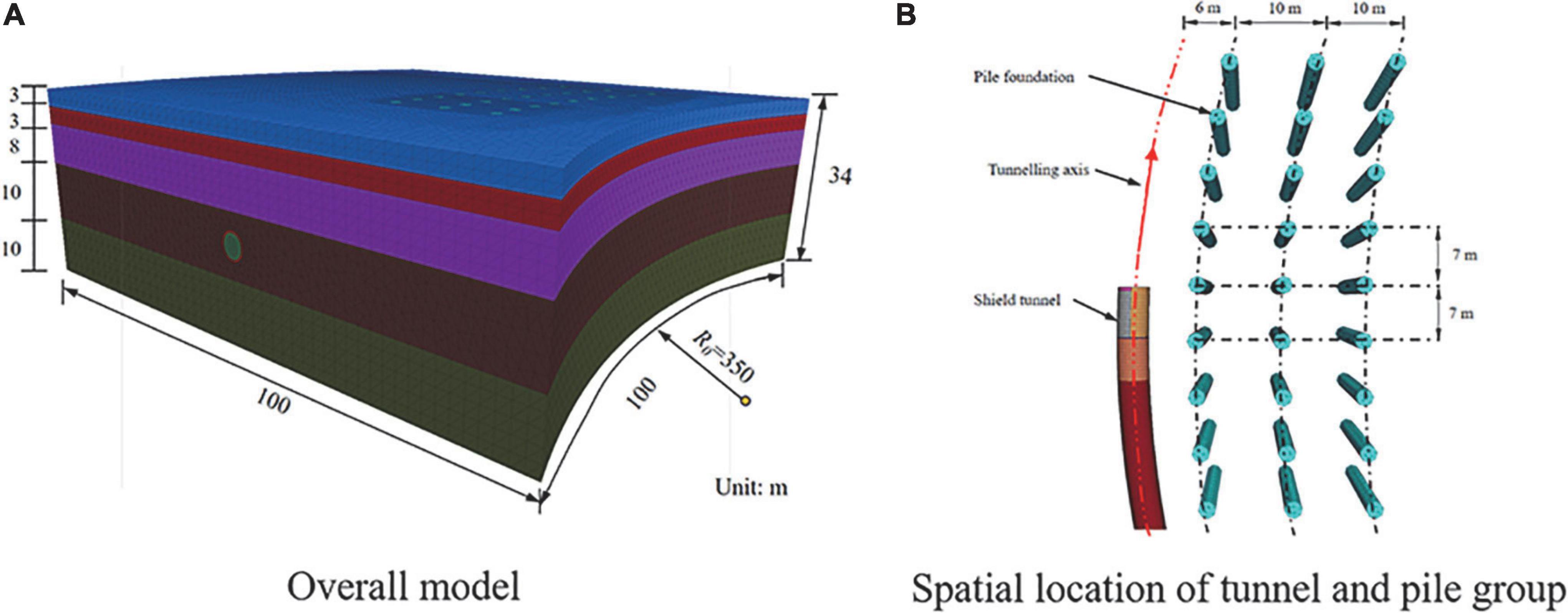
Figure 4. Model diagram. (A) Overall model and (B) spatial location of tunnel and pile group.
For the shield tunnels, the structures that need to be simulated include solidified slurry, unsolidified slurry, segment, cutter head, shield shell, IGST, and OG. Since the shield machine is in the process of tunnelling in the curved section, the cutter head and shield shell on the inner and outer sides of the curve section need to exert different forces, so it is necessary to divide the cutter head and the shield shell into two parts. The constructed shield tunnel model is shown in Figure 5.
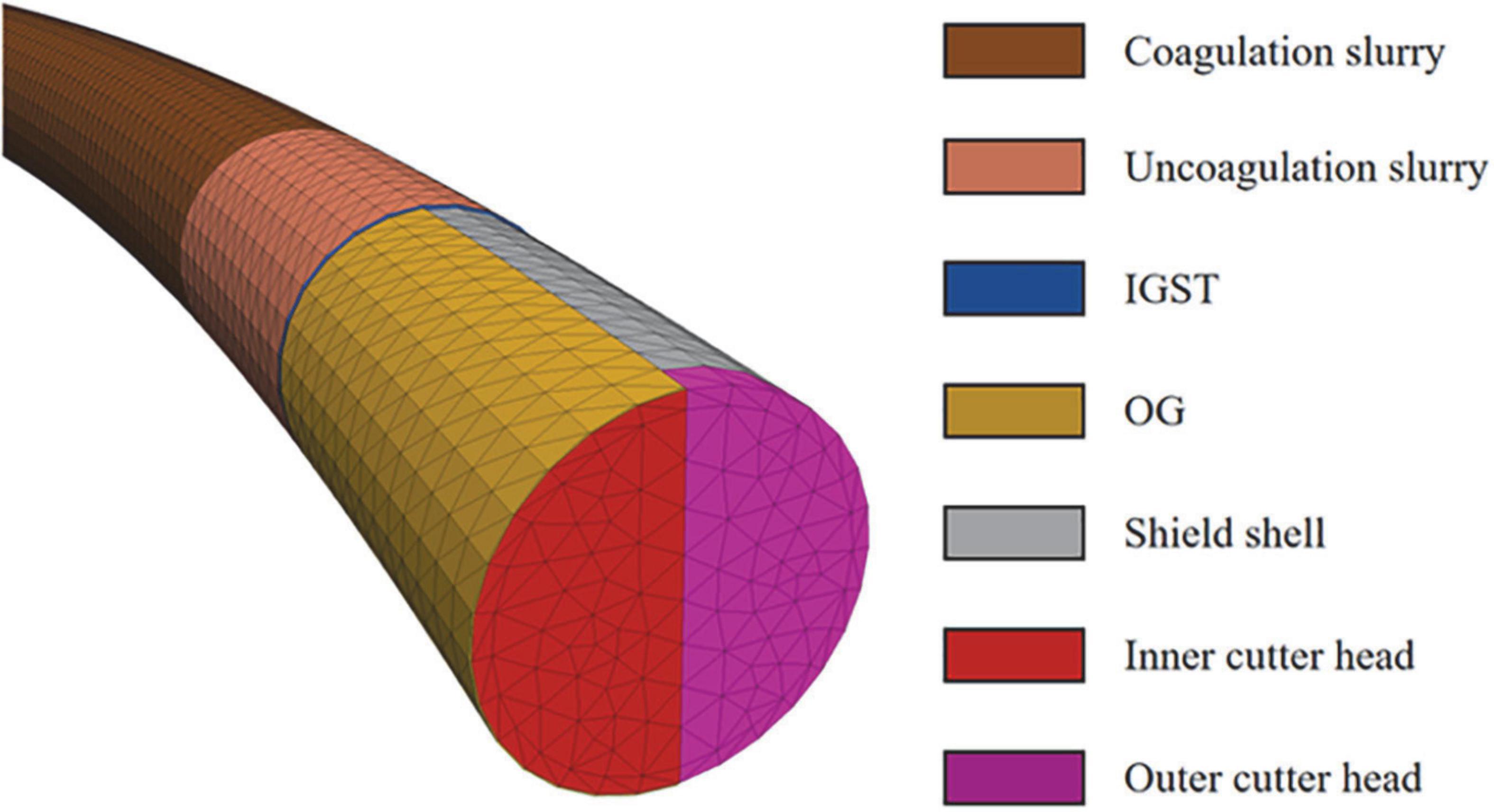
Figure 5. Shield tunnel model.
Material parameters
The soil is selected as an elastic-plastic solid element, and the Mohr–Coulomb constitutive is adopted. The material parameters of each soil layer are shown in Table 1. Segments, shield shells, cutter heads, grouting slurry, and piles are simulated by elastic solid elements. The strength of the unsolidified slurry is about 1/10 of the strength of the solidified slurry (Oggeri et al., 2021). The material parameters are shown in Table 2.
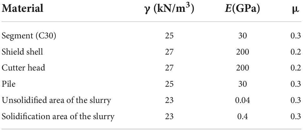
Table 2. Simulation unit parameters.
Acting loads
To simulate the tunnelling process of the shield machine, the force of the shield machine during the tunnelling needs to be considered in the numerical calculation model. The research points out that the front thrust of the shield machine, the shield shell friction and the grouting pressure are the main forces in the excavation process of the shield machine. The frontal thrust is about 1.2 times the static earth pressure of the excavation surface. During the excavation in the curve section, the frontal thrust exerted by the inner cutter head is smaller than that of the outer cutter head. According to the test excavation data, the ratio of the two is about 1.5 when the inner over-excavation measures are taken, and the ratio of the two is about 2.5 when the over-excavation measures are not taken. The shield shell friction is about 0.1 times that of the static earth pressure. Although the over-cutting of the inner soil is taken, it is still unavoidable that the inner shield will be squeezed by the soil more than the outer shield. The friction resistance ratio can be taken as 1.5–2.5. When no over-cutting measures are taken, the inner shield shell will be more severely squeezed by the soil, and the asymmetric distribution of the friction resistance distribution of the shield shell will be higher. According to the construction experience, no over-excavation is adopted. When taking measures, the friction ratio of the inner and outer shield shells is 3–5. According to the distribution of soil layers and the design scheme of the project, it is calculated that the frontal thrust exerted by the inner cutter head is 194 kPa, the frontal thrust exerted by the outer cutter head is 292 kPa, and the friction exerted on the inner shield shell is 37.5 kPa. The friction applied to the outer shield shell is 16.1 kPa, the additional grouting pressure is 200 kPa, and the action range of additional grouting pressure is the unsolidified slurry area.
The upper surface of the model is set as a free boundary condition, the bottom and sides are subjected to normal constraints, and the influence of groundwater seepage on the results is not considered in the calculation process. The calculation process is divided into three steps. First, the in-situ stress is balanced, then the displacement after the initial in-situ stress balance is zeroed, and the initial in-situ stress on-site is retained. Then, the elastic material is given to the pile, and a vertical uniform load of 1200 kPa is applied to the top of the pile. Simulate the force of the superstructure, and submit the calculation to obtain the stress on-site after the pile action. Finally, the displacement on-site after the pile action is reset to zero, and the properties of the shield machine and tunnel reserved element are changed to complete the tunnelling simulation of the shield machine.
Discussion
Surface subsidence
Figure 6 is the cloud map of surface subsidence. The surface in front of the cutter head is slightly uplifted, while the surface subsides near and behind the cutter head. From the cloud map, the maximum surface subsidence is 18.6 mm, which meets the construction control standard (maximum surface subsidence < 30 mm). To compare the FDM calculation results, analytical results and on-site monitoring values, the lateral surface subsidence (x = 0 m, x =−10 m) and the surface longitudinal subsidence curve (y = 0 m, y = 10 m) were extracted. The comparison of surface subsidence values is shown in Figure 7.
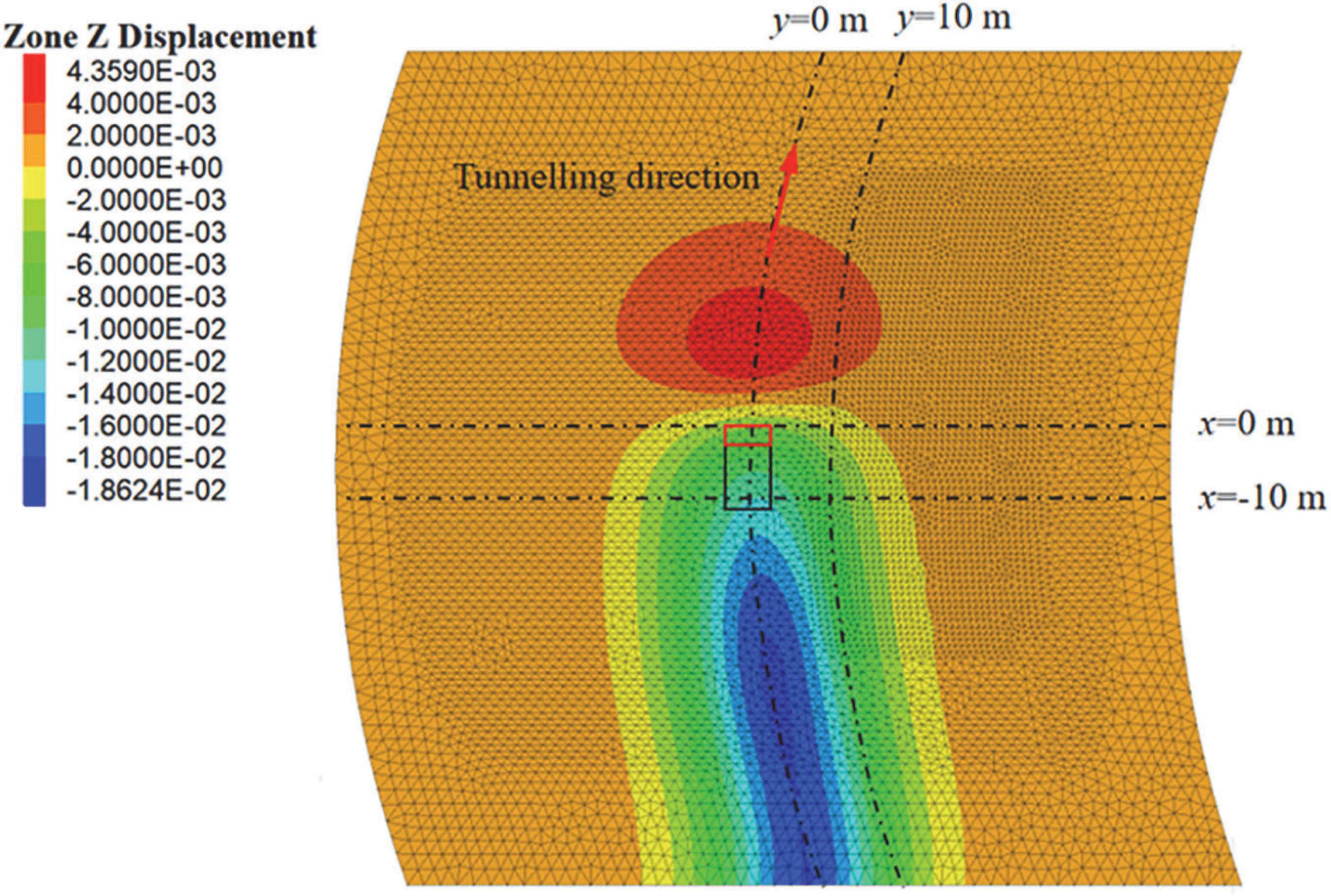
Figure 6. Surface subsidence cloud map.
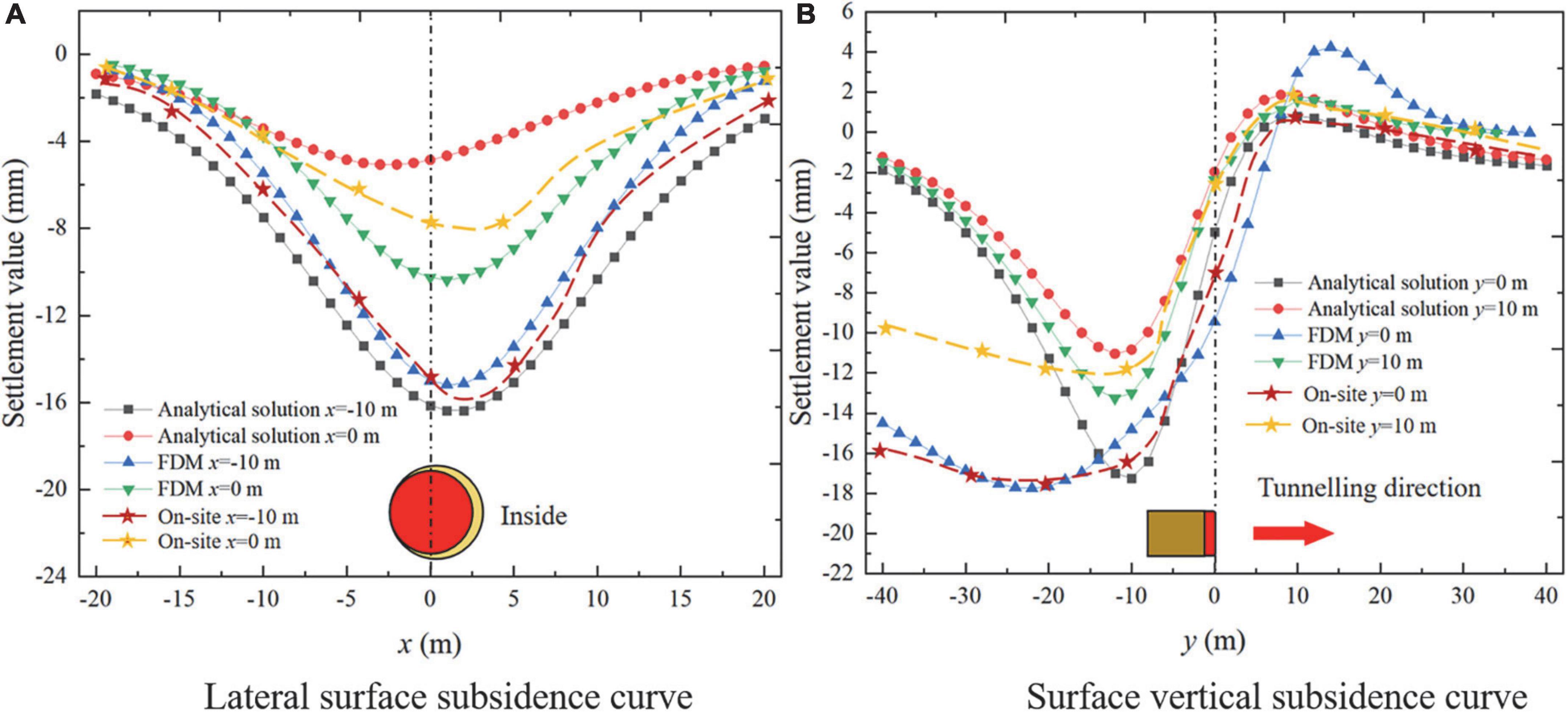
Figure 7. Surface subsidence curve. (A) Lateral surface subsidence curve and (B) surface vertical subsidence curve.
As you can see from Figure 7:
(1) The distribution of lateral subsidence of the surface is a “V”-shaped distribution, but the surface subsidence is not symmetrically distributed. The maximum lateral subsidence point of the surface is not located on the central axis. Still, it appears inside the curve section, which is different from the law of surface subsidence of the straight section. The additional frontal thrust, the shield shell friction and the asymmetric distribution of the over-cutting gap may be the reasons for the asymmetric distribution of the surface subsidence;
(2) The lateral subsidence of the surface at x =−10 m is significantly more significant than that at x = 0 m, because the closer the monitoring section is to the IGST, the greater the subsidence value;
(3) The longitudinal subsidence distribution of the ground surface is an “S”-shaped distribution, and the numerical results are consistent with those shown in the cloud map. A slight uplift occurs on the surface in front of the cutter head, while subsidence occurs at the cutter head and behind the cutter head. The position of the maximum surface subsidence appears behind the shield tail;
(4) The longitudinal subsidence of the ground surface with y = 0 m is significantly larger than that with y =−10 m, and the closer to the tunnelling axis, the greater the longitudinal subsidence of the ground surface;
(5) From the comparison of lateral settlement and longitudinal settlement, it can be seen that the error of the maximum surface settlement value calculated by the three methods of analytical analysis results from the on-site monitoring data and numerical simulation data is small, which verifies the correctness of the analytical analysis formula and numerical calculation model. However, FDM and on-site monitoring data show that the surface subsidence remains unchanged behind the shield tail. This is because the soil is regarded as an elastic space in the analytical calculation, and the plastic deformation caused by excavation is ignored. In contrast, the plastic deformation of the soil usually causes stable surface subsidence after excavation disturbance.
Figure 8 hows the surface subsidence curves caused by various factors considered in this study; it can be seen that:
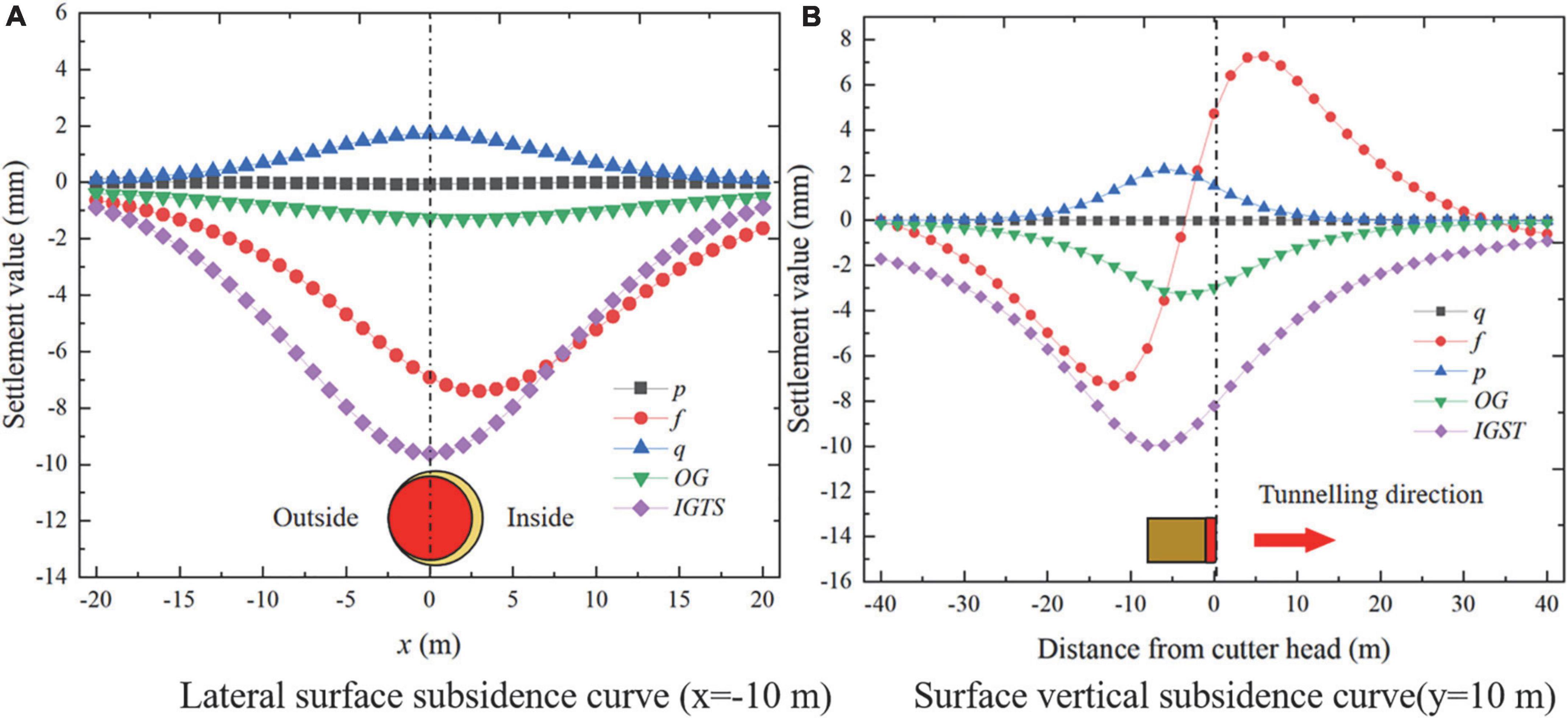
Figure 8. Surface settlement curve caused by construction factors. (A) Lateral surface subsidence curve (x =−10 m) and (B) surface vertical subsidence curve (y = 10 m).
(1) Figure 8A shows that the additional frontal thrust, shield friction, IGST, and OG will cause surface subsidence, and the contribution of the frontal thrust to the surface subsidence can be ignored. Shield Shell friction, IGST, and OG are the main factors leading to the surface subsidence, the surface deformation caused by the additional frontal thrust can be ignored, and the reasonable additional grouting pressure can control the surface subsidence. Therefore, when the shield machine tunnelling along the curve section, the shield friction, and OG are the main factors that cause the surface subsidence to be asymmetric. The additional grouting pressure will cause the surface uplift, so the surface settlement can be controlled by applying a moderate additional grouting pressure.
(2) Figure 8B shows that in front of the middle of the shield shell, the shield shell friction will cause the surface to uplift, and behind the middle of the shield shell, the shield shell friction will cause the surface to subside. The additional grouting pressure will cause the surface to bulge, and the maximum bulge is located behind the shield tail. Both OG and IGST cause surface subsidence and the maximum subsidence positions are located at the midpoint of the shield shell and the shield tail, respectively.
Analysis of pile foundation deformation
Analysis of pile foundation settlement
Figure 9 shows the settlement cloud diagram of the pile. It can be seen that the settlement law of the pile foundation is the same as that of the surface settlement. The pile foundation in front of the cutter head will bulge slightly, while the pile foundation behind the cutter head will settle. It can be seen from the pile foundation settlement cloud diagram that the pile foundation settlement reaches the maximum value at the position of x =−28 m, the maximum settlement value is 9.2 mm, and the maximum differential settlement rate is 0.045%. The above indicators are lower than the construction control standard (maximum settlement value < 20 mm, maximum differential sedimentation rate < 0.45%). Surface deformation and adjacent pile foundation deformation meet the construction control requirements. To compare the results of the three methods, the pile foundation settlement curve behind the cutter head (x = 0 m, x =−7 m, x =−14 m) was extracted, as shown in Figure 10.
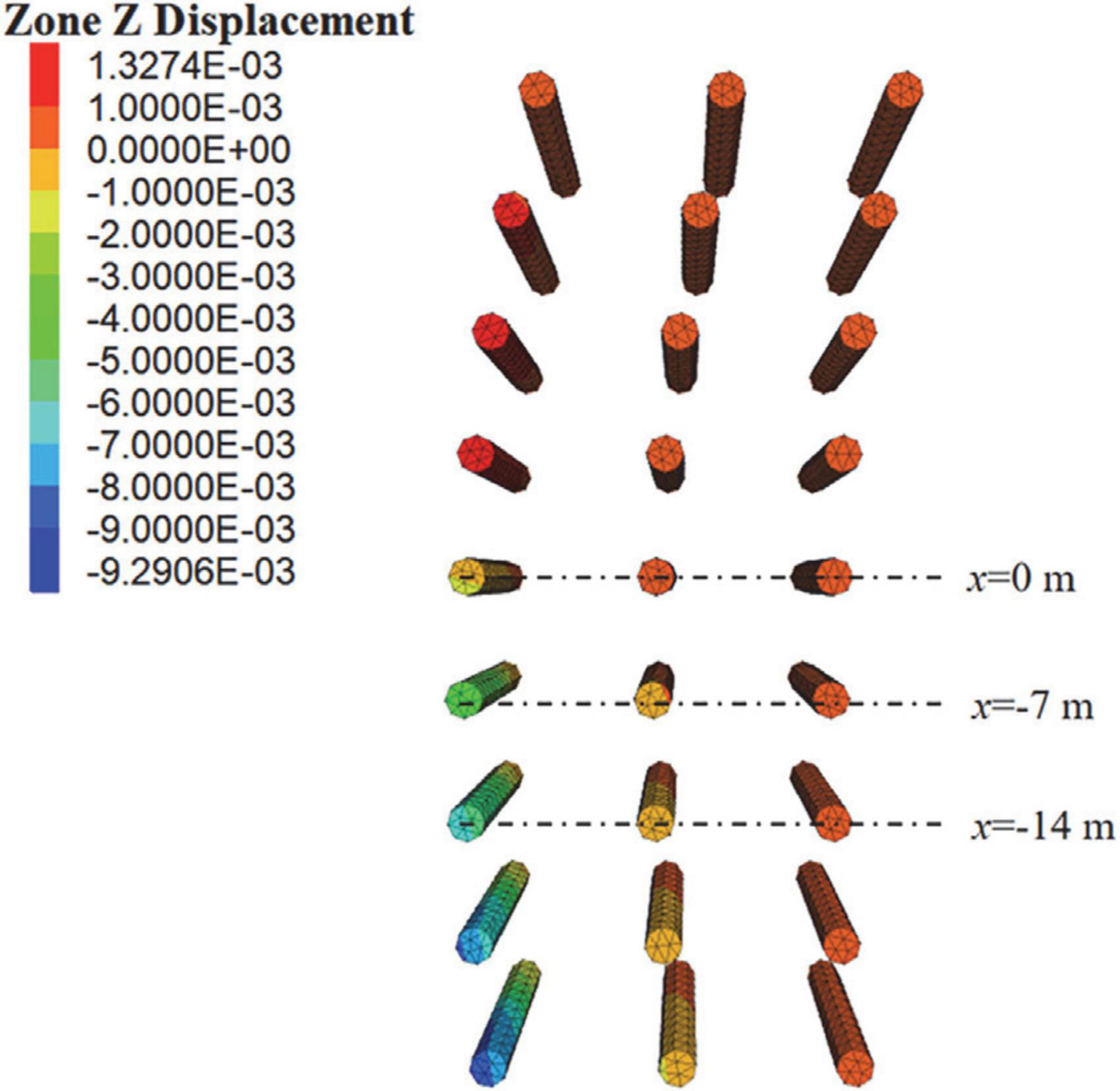
Figure 9. Pile foundation settlement cloud map.
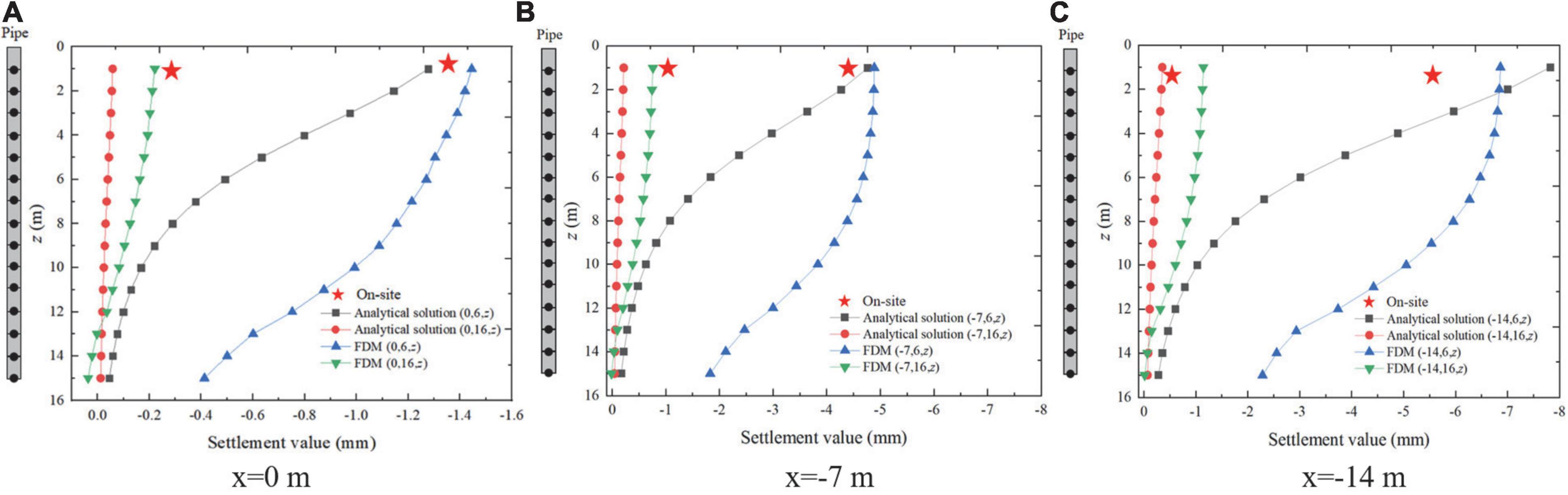
Figure 10. Pile foundation settlement curve. (A) x = 0 m, (B) x =−7 m, and (C) x =−14 m.
It can be seen that the error between the on-site monitoring value and the FDM calculation results and the analytical analysis results is small, which verifies the correctness of the model and the analytical analysis results. The analytical analysis results are consistent with the pile foundation settlement law obtained by the FDM numerical calculation results. The settlement decreases along the depth direction and reaches the maximum at the top of the pile, which is also proved by the study of Loganathan et al. (2001).
For the pile foundation with the same ordinate, the settlement value of the pile foundation closer to the tunnel excavation axis is larger. The settlement of the pile foundation behind the shield tail is larger than the pile foundation with the same abscissa. Since the numerical calculation model and the actual construction situation on the site did not include the pile foundation on the outside of the curve, the settlement of the pile foundation on the inside and outside of the curve section at x =−14 m was calculated through the analytical solution, as shown in Figure 11.
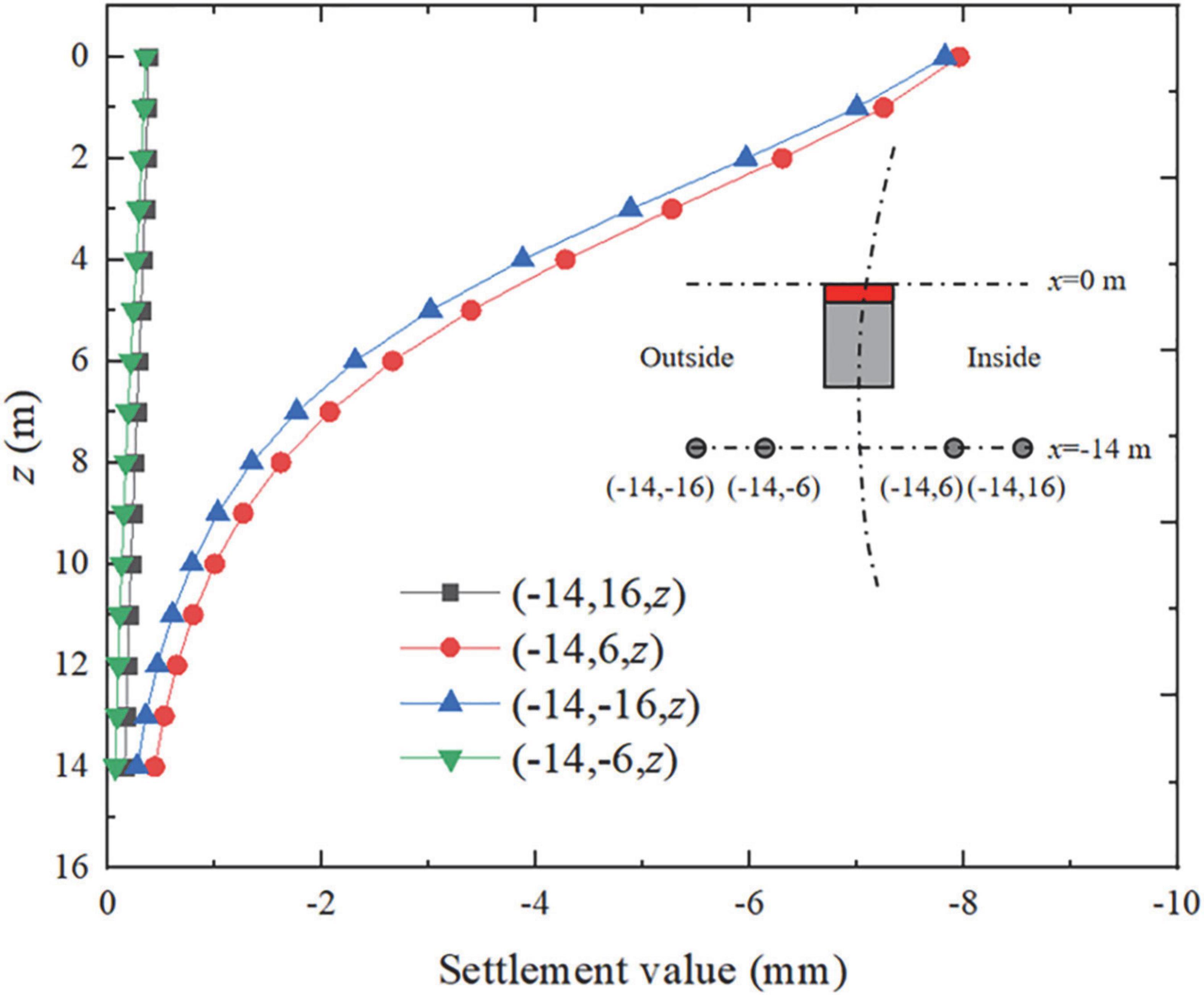
Figure 11. Comparison of settlement curves of pile foundations on both sides of inner and outer sides.
It can be seen that the settlement of the pile foundation located on the inside of the curve section is larger than the curve section, which is similar to the law of surface settlement. The maximum settlement of the pile foundation inside the curve section is 1.8% higher than outside. Due to the pile-soil coupling effect and the stiffness of the pile itself, the asymmetric settlement of the pile foundation on the inner and outer sides caused by the excavation of the curved section can be ignored.
Analysis of horizontal deformation of pile foundation
Similarly, it can be seen that the horizontal deformation of the pile foundation reaches the maximum at the top of the pile. At the position of the cutter head and in front of the cutter head, the horizontal deformation of the pile body is a positive deformation along the x-axis. After the shield machine passes through, the horizontal deformation of the pile is the negative deformation along the x-axis. Figure 12 shows the curve of the horizontal deformation of the pile foundation on the inside and outside of the curved section. It can be seen that it is consistent with the settlement law. The horizontal deformation of the pile foundation on the inside of the curved section is significantly larger than that on the outside of the curved section. The maximum horizontal deformation of the pile foundation on the inside and outside of the curved section The deformations are 7.1 and 6.5 mm, respectively, and the horizontal deformation of the piles located on the inner side of the curve segment is 9.2% larger than that on the outer side. The horizontal deformation of the pile foundation is more sensitive to the asymmetric distribution of the tunnelling factors.
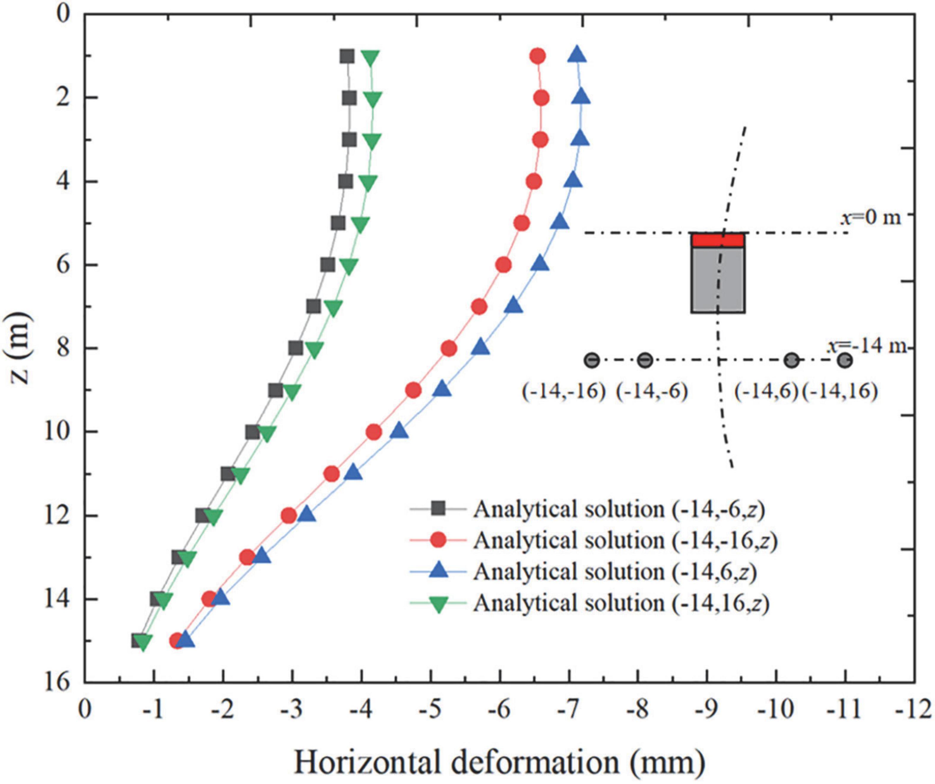
Figure 12. Horizontal deformation curve of pile foundation.
Conclusion
In this study, considering the tunnelling of the shield machine along the curve section, the analytical calculation formulas of adjacent pile foundation deformation and surface settlement caused by the additional thrust, the shield shell friction, the additional grouting pressure and the ground subsidence were deduced. The analytical prediction results are verified by an FDM and on-site monitoring data. The results show that:
(1) The errors among the on-site monitoring data, the FDM calculation results and the analytical calculation results are small, which verifies the correctness of the FDM and analytical calculation formula. The maximum settlement value of the ground surface is 18.2 mm, and the adjacent pile foundation’s maximum settlement value and horizontal deformation value are 9.2 and 9.4 mm, respectively. All of them meet the construction control requirements;
(2) The shield shell friction, IGST, and OG are the main factors leading to the surface subsidence, the surface deformation caused by the additional frontal thrust can be ignored, and the reasonable additional grouting pressure can control the surface subsidence;
(3) The surface settlement inside the curve section is larger than the outside of the curve section, and the surface settlement grooves are asymmetrically distributed. The pile foundation settlement and deformation inside the curve section are larger than those outside of the curve section. The asymmetrically distributed shield friction and OG are the main reasons that caused the settlement of the inside curve section to be larger than the outer side of the curve section;
(4) The deformation of the pile foundation located on the inner side of the curve segment is larger than that of the pile foundation outside the curve segment. The maximum difference is 9.2%, and the horizontal deformation of the pile foundation is more sensitive to the asymmetric distribution of shield tunnelling factors;
(5) The analytical formula derived from this paper can predict the disturbance risk of the shield machine to the surrounding environment during the tunnelling process to determine whether corresponding control measures need to be taken.
Data availability statement
The original contributions presented in the study are included in the article/supplementary material, further inquiries can be directed to the corresponding author.
Author contributions
FZ and YG were responsible for the writing. QH and ZH were responsible for the numerical simulation and data analyzing. FC was responsible for review and proofreading. All authors contributed to the article and approved the submitted version.
Funding
This research was supported by the Science and Technology project fund for Returned Students of Sichuan Province in 2021 (No. 212603), Opening fund of State Key Laboratory of Geohazard Prevention and Geoenvironment Protection (Chengdu University of Technology) (SKLGP2022K014), Japan Emergency Management Research Center of Xihua University (Nos. RBYJ2021-008 and RBYJ2021-005), Opening Foundation of Key Laboratory of Geohazard Prevention of Hilly Mountains, Ministry of Natural Resources (Fujian Key Laboratory of Geohazard Prevention) (Grant No. FJKLGH2022K005), On-campus Talent Introduction Project of Xihua University (Nos. Z212015 and Z201055), and Sichuan Province Key Laboratory of Higher Education Institutions for Comprehensive Development and Utilization of Industrial Solid Waste in Civil Engineering (No. SC_FQWLY-2022-Y-03).
Conflict of interest
The authors declare that the research was conducted in the absence of any commercial or financial relationships that could be construed as a potential conflict of interest.
Publisher’s note
All claims expressed in this article are solely those of the authors and do not necessarily represent those of their affiliated organizations, or those of the publisher, the editors and the reviewers. Any product that may be evaluated in this article, or claim that may be made by its manufacturer, is not guaranteed or endorsed by the publisher.
Abbreviations
q1, additional thrust inside the cutter head (kPa); q2, additional thrust outside cutter head (kPa); f1, inner shield friction resistance (kPa); f2, outer shield friction (kPa); p, additional grouting pressure (kPa); R, cutter radius (m); K, foundation reaction modulus (MPa); Gc, stiffness of the shear layer (MPa); EI, bending stiffness of the pile; Es, elastic modulus of soil (MPa); R0, turning radius (m); L, shield length (m); μ, Poisson’s ratio; g, formation loss parameter (m); H, depth of the cutter head (m); G, shear modulus of the soil (MPa); IGST, integrative gap at the shield tail; OG, over-cutting gap; D, diameter of the pile (m),t, the thickness of the shear layer (m).
References
Chen, W. C., Song, Z. P., Tian, W., and Wang, Z.-F. (2018). Shield tunnel uplift and deformation characterisation: A case study from Zhengzhou metro. Tunn. Undergr. Space Technol. 79, 83–95. doi: 10.1016/j.tust.2018.05.002
Chen, Z. Q., Ma, C. C., Li, T. B., and He, C. (2022). Experimental investigation of the failure mechanism of deep granite under high seepage water pressure and strong unloading effect. Acta Geotech. 193, 1–22. doi: 10.1007/s11440-022-01665-8
Deng, H., Fu, H., Shi, Y., Zhen, H., and Huang, Q. (2021). Analysis of asymmetrical deformation of surface and oblique pipeline caused by shield tunneling along curved section. Symmetry 13:2396. doi: 10.3390/sym13122396
Deng, H.-S., Fu, H.-L., Yue, S., Huang, Z., and Zhao, Y.-Y. (2022). Ground loss model for analyzing shield tunneling-induced surface settlement along curve sections. Tunn. Undergr. Space Technol. 119:104250. doi: 10.1016/j.tust.2021.104250
Festa, D., Broere, W., and Bosch, J. W. (2012). “Tunnel-boring in soft soil: A study on the driving forces applied to a slurry-shield TBM,” in Proceedings of the WTC 2012, tunneling and underground space for a global society, 18–24 May 2012, Bangkok.
Franza, A., Marshalla, A. M., Haji, T., Abdelatif, A. O., Carbonari, S., and Morici, M. (2017). A simplified elastic analysis of tunnel-piled structure interaction. Tunn. Undergr. Space Technol. 61, 104–121. doi: 10.1016/j.tust.2016.09.008
Gao, M. B., Cui, S. H., Li, T., Ma, C., Wu, Z., and Zhang, Y. (2022). Investigation on the expression ability of a developed constitutive model for rocks based on statistical damage theory. Lithosphere 2022:9874408. doi: 10.2113/2022/9874408
He, C., Jiang, Y., Yong, F., Kun, F., and Jun, W. (2013). Impact of shield tunneling on adjacent pile foundation in sandy cobble strata. Adv. Struct. Eng. 16, 1457–1468. doi: 10.1260/1369-4332.16.8.1457
Hu, H., Zhu, Y., Zhang, G., and Tu, P. (2021). The environmental effects induced by a metro shield tunnel side-crossing on adjacent pile foundations and its impact partition. Adv. Civ. Eng. 2021:8216724. doi: 10.1155/2021/8216724
Huang, Z., Zhang, H., Fu, H., Ma, S., and Liu, Y. (2020). Deformation response induced by surcharge loading above shallow shield tunnels in soft soil. KSCE J. Civ. Eng. 24, 2533–2545. doi: 10.1007/s12205-020-0404-8
Jongpradist, P., Kaewsri, T., Sawatparnich, A., Suwansawat, S., Youwai, S., Kongkitkul, W., et al. (2013). Development of tunneling influence zones for adjacent pile foundations by numerical analyses. Tunn. Undergr. Space Technol. 34, 96–109.
Lee, C. J., and Jacobsz, S. W. (2006). The influence of tunnelling on adjacent piled foundations. Tunn. Undergr. Space Technol. 21:430. doi: 10.1016/j.tust.2005.12.072
Lee, K. M., Rowe, R. K., and Lo, K. Y. (1992). Subsidence owing to tunnelling. I. Estimating the gap parameter. Can. Geotech. J. 29, 929–940. doi: 10.1139/t92-104
Li, S.-H., and Li, P.-F. (2021). Analytical solutions to ground settlement induced by ground loss and construction loadings during curved shield tunneling. J. Zhejiang Univ. Sci. A. 22, 296–313. doi: 10.1631/jzus.A2000120
Li, X., Zhou, X., Hong, B., and Zhu, H. (2019). Experimental and analytical study on longitudinal bending behavior of shield tunnel subjected to longitudinal axial forces. Tunn. Undergr. Space Technol. 86, 128–137. doi: 10.1016/j.tust.2019.01.011
Liang, R., Wu, W., Yu, F., Jiang, G., and Liu, J. (2018). Simplified method for evaluating shield tunnel deformation due to adjacent excavation. Tunn. Undergr. Space Technol. 71, 94–105. doi: 10.1016/j.tust.2017.08.010
Lin, C., Huang, M., Nadim, F., and Liu, Z. (2020). Embankment responses to shield tunnelling considering soil-structure interaction: case studies in Hangzhou soft ground. Tunn. Undergr. Space Technol. 96:103230. doi: 10.1016/j.tust.2019.103230
Liu, B., Yu, Z., Han, Y., Wang, Z., Zhang, R., and Wang, S. (2020). Analytical solution for the response of an existing tunnel induced by above-crossing shield tunneling. Comput. Geotech. 124:103624. doi: 10.1016/j.compgeo.2020.103624
Loganathan, N. (1998). Analytical prediction for tunneling-induced ground movements in clays. J. Geotech. Geoenviron. Eng. 124, 846–856. doi: 10.1061/(ASCE)1090-02411998124:9(846)
Loganathan, N., Poulos, H. G., and Xu, K. J. (2001). Ground and pile-group responses due to tunnelling. Soils Found. 41, 57–67. doi: 10.3208/sandf.41.57
Ma, B. H., Hu, Z. Y., Li, Z., Cai, K., Zhao, M.-H., He, C.-B., et al. (2020). Finite difference method for the one-dimensional non-linear consolidation of soft ground under uniform load. Front. Earth Sci. 8:111. doi: 10.3389/feart.2020.00111
Miao, F., Wu, Y., Török, Á, Li, L., and Xue, Y. (2022). Centrifugal model test on a riverine landslide in the three gorges reservoir 1 induced by rainfall and water level fluctuation. Geosci. Front. 13:101378. doi: 10.1016/j.gsf.2022.101378
Miao, Y., He, H., Yang, Q., and Yang, S. (2020). Analytical solution considering the tangential effect for an infinite beam on a viscoelastic Pasternak foundation. Appl. Math. Model. 85, 231–243. doi: 10.1016/j.apm.2020.03.031
Min, Y., Sun, Q., Li, W. C., and Ma, K. (2011). Three-dimensional finite element analysis on effects of tunnel construction on nearby pile foundation. J. Cent. South Univ. Technol. 18, 909–916. doi: 10.1007/s11771-011-0780-9
Mindlin, R. D. (1936). Force at a point in the interior of a semi-infinite solid. Physics 7, 195–202. doi: 10.1063/1.1745385
Mroueh, H., and Shahrour, I. (2002). Three-dimensional finite element analysis of the interaction between tunneling and pile foundations. Int. J. Numer. Anal. Methods Geomech. 26, 217–230.
Nematollahi, M., and Dias, D. (2019). Three-dimensional numerical simulation of pile-twin tunnels interaction – case of the shiraz subway line. Tunn. Undergr. Space Technol. 86, 75–88. doi: 10.1016/j.tust.2018.12.002
Oggeri, C., Oreste, P., and Spagnoli, G. (2021). The influence of the two-component grout on the behaviour of a segmental lining in tunnelling. Tunn. Undergr. Space Technol. 103750:109. doi: 10.1016/j.tust.2020.103750
Sagaseta, C. (1987). Analysis of undraind soil deformation due to ground loss. Geotechnique 37, 301–320. doi: 10.1680/geot.1987.37.3.301
Soomro, M. A., Mangi, N., Mangnejo, D. A., and Noor Ahmed, M. (2021). 3D centrifuge and numerical modelling of lateral responses of a vertical loaded pile group to twin stacked tunnels. Eur. J. Environ. Civ. Eng. 26, 5517–5544. doi: 10.1080/19648189.2021.1907227
Xie, X., and Tang, G. (2017). Effects of curved shield tunnelling adjacent to existing power tunnel. Eur. J. Environ. Civ. Eng. 22, s164–s178. doi: 10.1080/19648189.2017.1419882
Zhang, Y. H., Dai, Y. S., Ying, W., Huang, X., Xiao, Y., and Pei, Q. M. (2021). Hydrochemistry, quality and potential health risk appraisal of nitrate enriched groundwater in the Nanchong area, southwestern China. Sci. Total Environ. 784:147186. doi: 10.1016/j.scitotenv.2021.147186
Zhang, Z., Huang, M., Xu, C., Jiang, Y., and Wang, W. (2018). Simplified solution for tunnel-soil-pile interaction in Pasternak’s foundation model. Tunn. Undergr. Space Technol. 78, 146–158. doi: 10.1016/j.tust.2018.04.025
Keywords: curve section, asymmetrical construction factors, over-cutting gap, pile foundation, asymmetrical deformation
Citation: Zeng F, Gao Y, Chen F, He Q and He Z (2022) Calculation of surface settlement and pile foundation deformation caused by shield machine tunnelling along curve section. Front. Ecol. Evol. 10:1019785. doi: 10.3389/fevo.2022.1019785
Received: 15 August 2022; Accepted: 10 October 2022;
Published: 25 October 2022.
Edited by:
Yunhui Zhang, Southwest Jiaotong University, ChinaReviewed by:
Xin Yang, Fujian University of Technology, ChinaShiru Wen, Jiangxi University of Science and Technology, China
Copyright © 2022 Zeng, Gao, Chen, He and He. This is an open-access article distributed under the terms of the Creative Commons Attribution License (CC BY). The use, distribution or reproduction in other forums is permitted, provided the original author(s) and the copyright owner(s) are credited and that the original publication in this journal is cited, in accordance with accepted academic practice. No use, distribution or reproduction is permitted which does not comply with these terms.
*Correspondence: Zhihao He, aGV6aGloYW9oYW9AMTYzLmNvbQ==; Feng Zeng, emVuZ2ZlbmcyNTIyQDE2My5jb20=