Abstract
Each year, fires in the wildland-urban interface (WUI)—the place where homes and wildlands meet or intermingle—have caused significant damage to communities. To contribute to firefighter and public safety by reducing the risk of structure ignition, fire blankets for wrapping a whole house have been investigated in the laboratory and prescribed wildland fires. The fire blankets aim to prevent structure ignition (1) by blocking firebrands to enter homes through vulnerable spots (gutters, eaves, vents, broken windows, and roofs); (2) by keeping homes from making direct contact with flames of surrounding combustibles (vegetation, mulch, etc.); and (3) by reflecting thermal radiation from a large fire within close range (adjacent burning houses or surface-to-crown forest fires) for a sustained period of time. In the laboratory experiment, two-layer thin fabric assemblies were able to block up to 92% of the convective heat and up to 96% of the radiation (with an aluminized surface). A series of proof-of-concept experiments were conducted by placing instrumented wooden structures, covered with different fire blankets, in various fires in ascending order of size. First, birdhouse-sized boxes were exposed to burning wood pallets in a burn room. Second, wall-and-eave panels were exposed to prescribed fires climbing up slopes with chaparral vegetation in California. Finally, a cedar shed was placed in the passage of the prescribed head fire in the Pine Barrens in New Jersey. The experiments demonstrated both successful performance and technical limitations of thin fire blankets. The key success factors in protecting the WUI structure are (1) the fire blanket's heat-blocking capability, (2) endurance under severe heat-exposure high-wind conditions, and (3) proper installation. Additional studies are needed in the areas of advanced material/layer development, blanket deployment methods, and multi-structure protection strategies.
Introduction
Background
Housing development in the wildland-urban interface (WUI), i.e., the place where homes and wildlands meet or intermingle, is growing (U.S. Fire Administration, 2002; Radeloff et al., 2005, 2018; Hammer et al., 2007; Stewart et al., 2007; Stein et al., 2013; Kramer et al., 2018). Between 1990 and 2010, the WUI was the fastest-growing land use type in the United States, and 97% of new WUI areas were the result of new housing rather than increases in wildlife vegetation (Radeloff et al., 2018). WUI fires have caused significant damage to communities (Cohen, 1999; Mell et al., 2010; Stein et al., 2013). The magnitude of the fire damage is increasing as well. Major wildfires California in 2018 caused over $12 billion in property damage (Evarts, 2019). In 2018, the largest (the Mendocino Complex Fire burned 459,123 acres), most destructive (18,804 structures were destroyed in the Camp Fire), and deadliest (86 deaths in the Camp Fire) wildfires in modern California history have occurred at the same time (Cal Fire, 2018; Verzoni, 2019). Like urban conflagrations a century ago, wildfire in urban and suburban settings poses one of the greatest fire challenges of our time (Grant, 2018).
The WUI fire problem can be thought of as a structure ignition problem (Cohen, 1991; Mell et al., 2010) and an effective approach to mitigating the problem is to reduce the potential for structure ignition (Cohen and Stratton, 2008). Thus, if the structure ignition is prevented, WUI fire damage can be reduced and the safety of the public and firefighters will be improved. In a wildland fire, firebrands/embers (i.e., burning branches, leaves, or other materials) are lofted and carried by the wind and start distant spot fires. The cause of the initial structure ignitions in a WUI community is predominately due to exposure to firebrands (embers), generated by a wildfire or burning structures, and/or the heat flux from flames. Post-fire studies (Leonard, 2009; Maranghides and Mell, 2009; Morgan and Leonard, 2010) suggest that the firebrands are a major cause of structural ignition of WUI fires in the U.S. and Australia. A case study (Cohen and Stratton, 2008) revealed that burning homes and surrounding vegetation ignited adjacent homes initiating a “domino effect” of home destruction without wildfire as a major factor. Most of the homes (193 out of 199) destroyed and damaged ignited homes in two ways: (1) from spreading through surface fuels within the residential area that contacted homes and/or from firebrands and/or (2) from thermal exposure directly related to burning residences from structure flames and firebrands. Cohen and Stratton (2008) also concluded, “Firefighters were overwhelmed in their attempt to prevent the residential fire spread due to multiple homes burning simultaneously. However, more homes would have burned without their intervention.” Another case study (Maranghides and Mell, 2009) found that firebrands ignited at least 60% of the destroyed structures in the WUI community. The likelihood of a structure's ignition is dependent both on its physical attributes (e.g., roofing material, decks, and vents) and the fire exposure conditions (e.g., magnitude and duration of heat flux from flames and firebrands).
Potential structure ignitions due to uninterrupted fire spread through vegetation to the structure were also reported in the perimeter of the community (Maranghides and Mell, 2009). Thus, the location of the structure in the WUI development community (perimeter or interior) is also an influencing factor (Maranghides and Mell, 2009). Mell et al. (2010) emphasized the research needs to characterize the exposure conditions and the vulnerability of a given structure design or building material when subjected to a given exposure. Butler (2010) pointed out that in the past, it had been stated that, at least for crown fires, radiant energy transport dominated the energy exchange process (Albini, 1986). More recently, laboratory and field studies indicated that convection might be just as critical to the energy transport as radiation (Anderson et al., 2010; Finney et al., 2010; Frankman et al., 2010). In the international crown fire modeling experiments in 1999 (Putnam and Butler, 2004; USDA Forest Service, 2009), one of the fire shelter testing showed that an average heat flux was measured at 80 to 100 kW/m2, while peak heat flux was over 200 kW/m2, and maximum (environment) temperature exceeded ≈1,300°C. Ignition of structures by burning vegetation (crown fires) is also possible (Cohen, 1999; Evans et al., 2004). In more recent fire spread experiments (Morandini et al., 2007), the peak heat fluxes measured during the four experiments increased in the range of 39–112 kW/m2 with flame front size in the field (5 m × 5 m to 30 m × 50 m).
To mitigate risks of ignition of homes, there are resources available to homeowners (Cal Fire, 2006; Ahrens, 2010; Quarles et al., 2010; Stein et al., 2013; ICC, 2018; NFPA, 2018). NFPA 701 (2018)—Standard for Reducing Structure Ignition Hazards from Wildland Fire provides a methodology for assessing wildland fire ignition hazards around existing structures, residential developments, and subdivisions. The risk-assessment and risk-reduction guidelines can use the concept of home or structure ignition zone [NFPA 701, 2018] or defensible space (ICC, 2018) to categorize the recommended treatment of structure and vegetative fuels (Mell et al., 2010).
The role of structure-to-structure fire spread in WUI settings has not been given as much attention as vegetative-to-structure fire spread, which is valid for WUI communities with sufficiently low housing density (Mell et al., 2010). Post-fire analysis found that structure-to-structure fire spread played a key role in the overall fire behavior, and heat fluxes from both the flame fronts and firebrands produced by structures were instrumental in maintaining fire spread to surrounding structures and vegetation (Mell et al., 2010). Mell et al. (2010) pointed out a need to assess the effectiveness of the guidelines across a range of WUI fire setting (e.g., housing density, terrain, vegetative fuels, winds, wildland fuel treatments) and exposure conditions (heat flux from flames and firebrands generated by burning vegetation or burning structures). The 2018 Camp Fire in California swept through and destroyed the town of Paradise, possibly by the “domino effect” in structure-to-structure fire. In residential developments and subdivisions with relatively high housing density with limited space surrounding homes, the implementation of the ignition-risk reduction guidelines may not be feasible. Therefore, there is an urgent need to implement technology-based solutions that can diminish ignition vulnerabilities of structures to firebrand showers and heat flux from flames, including structure-to-structure fire spread in high housing density.
While wildfires can rage for days, weeks, or even months, the duration required to protect homes by fire blankets may range widely from minutes to hours, depending on various factors, e.g., housing density, terrain, vegetative fuels, winds, heat flux from flames, and firebrands. In a relatively low housing density, a critical period can be several minutes during a wildfire front passes. Airborne embers or other materials from burning vegetation pose a threat to ignite a house for a much longer time, an order of 30 min before and after the spreading fire front. In a relatively high housing density, e.g., suburban community or urban setting, neighboring burning houses must threat the ignition of the structure for over an hour, possibly hours, if there is no intervention by firefighters.
Conventional measures in practice to prevent the structure ignition include the application of aqueous fire suppressants and retardants in the forms of foams, gels (USDA Forest Service, 2007), or water sprays, to the structure and/or surroundings prior to the arrival of the wildland fire front. Aerial firefighting using aircraft is also conducted to combat wildfires by dropping water or flame retardant. The advantage of these liquid spray coatings is that they can be applied to the structure parts with complex shapes (including decks, eaves, fences, etc.) and vegetation. The drawback is that they need water (at least 30 psi for ground operations), and spray application is difficult under windy conditions, and foams can be blown away by the wind before the wildfire front arrives. These coatings lose effectiveness with time as a result of water evaporation. Although gels are more effective than foams or water against thermal radiation exposure, their effectiveness decreased significantly even within an hour.
By contrast, more effective and long-lasting means of thermal shielding may be fire blankets, a.k.a. structure wraps. The U.S. Forest Service has occasionally been using the structure wraps to protect historic cabins from wildfires (Kuruvila, 2008; Miller-Carl, 2008; Backus, 2013; Gabbert, 2013; Montanez, 2014; Anon, 2018). Anecdotal evidence and technical know-how on the application of cabin wrapping have been accumulated over the last two decades. A typical description of the structure wrap in the news articles is “the wraps are similar to ones firefighters use for personal safety on the job, though they are thicker and the Forest Service says they are not exactly fireproof (Stephen, 2014).” Despite a common functionality between the fire blanket and the fire shelter as thermal insulation, the design goals (e.g., the interior temperature limit and the content endurance) in protecting a building structure are very different from those for a human body. Unfortunately, scientific research has rarely been conducted.
Literature Review
Fire blankets have been used for both fire suppression and protection. The literature on fire blankets is scarce probably because the basic research has not been fully conducted and the R&D efforts have mainly been made sporadically at manufacturers without dissemination of test results other than the specifications of final products. A few specifications available are: ASTM F 1989 (2005), the British Standards BS EN 1869 (1997); British Standards BS 7944 (1999), and the General Services Administration's procurement specifications (General Services Administration A-A-50230, 1987; General Services Administration A-A-54409, 1991; General Services Administration A-A-54629, 1992). More importantly, there have been no adequate performance-based standards and ongoing third-party certification to those standards specifically designed for fire blankets. As a result, fire blanket industry voluntarily used related compliance standards for flammability tests of blankets or fabrics such as ASTM D 4151 (2001) or NFPA 1144 (2004). In early 2007, the American National Standards Institute adopted ANSI/FM 4950 (2007), a performance-based standard for welding curtains, blankets and pads. Fabrics used for hot work operations such as welding and cutting are also commonly known as fire blankets. The performance of fire blankets for protection of stored ammunition was studied (Tewarson et al., 2001; Hansen and Frame, 2008).
Despite their easiness in handling compared to fire extinguishers, fire blankets have been used for smothering relatively small incipient fires only. They are generally not recommended to be used for a liquid fire or lab equipment as it can cause the fire spread, although some products are claimed to be useable for cooking oil fires. The old fire blankets, made of asbestos, were excellent at putting out fires. However, asbestos blankets were banned because of health hazards, and non-combustible glass fiber was chosen as a substitute material. For general purposes, including personal and burned victim protection, fire-resistant-treated cotton or wool blankets with or without a layer of gelled water are used in the military, fire departments, steel mills, etc. More recent fire blankets are made of fire and heat resistant aramid fabrics, which are more effective than wool blankets, and will not melt, drip, burn, or support combustion in the air. New types of fire blankets have been invented: non-woven polyester impregnated with a hydrous gel (Romaine, 1986), fabric made of mineral material containing basalt or a sodocalcic glass (Calderwood et al., 2006), or chemical compound which melts and reacts endothermically (Goldberg, 2006).
For the protection of building structures, various ideas of fire blanket deployment have been documented as the U.S. patents (Wagner,
1944; Ballinger,
1973; McQuirk,
1989; Gainer,
1992; Floyd,
1997; Hitchcock,
1997; Jones and Smith,
1998; Gleich,
1999; Kilduff and Oswald,
2003; Meyer and Kessler,
2004). Various concepts reported previously include:
Blankets, which are rolled around cylinders inside housings attached to various parts of a building, are deployed by rotating the cylinders typically by electric motors.
A blanket, which is stored in a container on the roof of a building or transported by a crane or helicopter, is deployed by using thrusting devices (compressed-gas-powered projectiles or rockets), which spread the blanket over the building.
A blanket is manually deployed to cover and enclose a building entirely.
Blankets are manually deployed to cover windows of a building to prevent the incoming wind, which would fuel the fire.
Although numerous methods for wrapping a home with fire blankets using the thrusting devices (Item 2) have long been proposed, the ideas are not necessarily verified nor validated. Item 1, Item 3, and Item 4 have been put into practice. The USDA Forest Service's effort to protect historic cabins using the commercial structure wraps (Anon, 2019) is among the Item 3 approach.
In contrast to fire blankets, the literature on firefighter protective clothing fabrics and domestic and international standard test methods exist. Various fire-resistive materials and their combinations have been developed for firefighter protective clothing, consisting of shell fabric, vapor barrier, and thermal barrier. These fabrics are resistive in fire fighting environments (Davis et al., 2006; Donnelly et al., 2006; Madrzykowski, 2007). Furthermore, new materials are also being developed. For example, carbon nanotube fabric, which possesses great thermal conductivity and reflectivity, is currently tested for fire fighter protective clothing at the National Institute of Standards and Technology (Anon, 2006). It may become a candidate for the shell fabric for fire blankets once it becomes economically viable through commercialization in the future. Heat transfer models have been developed for fire fighter's protective clothing (Hirschler, 1997; Mell and Lawson, 1999; Torvi and Dale, 1999a,b; Song et al., 2004; Chitrphiromsri and Kuznetsov, 2005; Chitrphiromsri et al., 2006; Torvi and Threlfall, 2006). The models consist of radiative and conductive heat transfer of several layers of materials. The computed time history compared reasonably with measurement although restricted to lower temperature.
On the other hand, fire shelters are deployed in entrapment situations when firefighters feel they need to use it to prevent possible burn injury or death (National Wildfire Coordinating Group, 2019). In 2002, the U. S. Forest Service selected a new-generation fire shelter possessing improved insulation and a vapor barrier to protect firefighters (USDA Forest Service, 2003, 2008a,b; Petrilli, 2006; Anon, 2009). The old-style fire shelter was deployed 1,100 times and saved 300 lives but caused 20 fatalities, while the new design (Model 2002) statistics are: 166 deployments, 26 saved lives, and 21 fatalities (National Wildfire Coordinating Group, 2019). In 2013, the Yarnell Hill Fire in Arizona overran and killed 19 firefighters. The firefighters had apparently deployed fire shelters against the burnover. More recently, the NASA Langley Research Center and the U.S. Forest Service collaborated and two of the prototype fire shelters are NASA designs. The National Wildfire Coordinating Group (NWCG) board will decide to adopt the new fire shelter designs or continue using the current fire shelter, or a combination of both.
Based on the background and literature survey described above, the following observations can be made:
Although the materials for fire blankets for wrapping buildings and fire shelters for firefighter emergency protection are similar, their performance requirements are vastly different.
Fire blankets have not undergone proof-of-concept tests as has been done for fire shelters. Fire blankets also lack scientific research compared to firefighter clothing.
Although numerous methods for wrapping a home with fire blankets have long been proposed (and often patented), the ideas are not necessarily verified nor validated.
U.S. Forest Service used structure wraps (fire blankets) to protect isolated historic cabins during wildfires pass over them. A lot of know-how on proper manual installation must be accumulated but no technical documentation of the data is available in the literature.
The effectiveness of fire blankets for longer heat exposures is unknown despite its importance in the case of the structure-to-structure ignition in high housing density areas typical of a WUI community.
Objectives
In previous papers (Hsu et al., 2011; Takahashi et al., 2014), thermal response characteristics of more than 50 relatively thin fire blanket materials have been investigated experimentally and selected cases have been analyzed computationally. Each specimen was exposed to a convective or radiant heat flux. A relatively thin fire blanket operating at high temperatures can efficiently block heat by radiative emission and reflection coupled with thermal insulation. The level of protection afforded depends on the fabric material as well as the incident heat flux level and type (convective or radiative) and exposure time. Among the materials tested, relatively thin (~1 mm) fiberglass or amorphous silica fabric laminated with aluminum foil performed reasonably well for a wide range of conditions.
The numerical modeling was performed (1) to simulate the heat transfer phenomena in the laboratory experiment (Hsu et al., 2011) and (2) to optimize the performance of fire blanket materials (Brent, 2012). The former is the physics-based modeling using the one-dimensional transient heat-transfer equation, which includes radiation as well as conduction in the interior of layered fire blanket materials. The latter includes three optimization studies on a one-dimensional, quasi-steady-state heat transfer model to optimize the performance of a fire blanket for protecting a structure from an exterior fire. Physical and optimization models would be useful for the development of advanced fabric materials and combined layer ensembles.
There are still various aspects of the subject matter needed to be studied. Topics include the heat-blocking mechanisms and performance of single and multi-layer fabrics in the laboratory and in actual wildland fires. The overall objectives of this study are to gain better understanding of the heat-blocking mechanisms and ignition prevention performance of single and multiple-layer fabric materials through the well-controlled laboratory experiments and larger-scale field fire-exposure tests. This paper reports previously unpublished laboratory experimental results for multi-layer fabric ensembles and the field fire test results using single-layer fabrics in increasing order of scale.
Limitations and Success Criteria
It should be noted that there are limitations of both the laboratory experiments and larger-scale fire-exposure tests. The laboratory experiments yield reproducible data of the thermal protection properties of materials under well-controlled conditions. The large-scale fire-exposure tests are proof-of-concept trials for the feasibility of the fire blanket protection method. When applying findings in the laboratory-scale to large-scale testing or a real fire, there are technical difficulties in scaling up the results. The difficulties stem mainly from differences in the substrate settings and exposure conditions. The laboratory experiments determine the material properties without a specific substrate at a fixed heat flux (84 kW/m2), whereas the field fire tests examine the damage to the blanket and substrate (wood) (ignition or no-ignition) for particular structures under natural conditions of fluctuating heat flux, wind speed, air temperature, and different fire exposure durations. The incident heat flux by direct flame contact or a radiant heater in the present laboratory experiments is within a range of values measured in the large-scale crown fire experiments (Putnam and Butler, 2004; USDA Forest Service, 2009) and more recent fire spread experiments (Morandini et al., 2007) as mentioned above. Most importantly, in the outdoor field tests, such exposure conditions are dependent on the weather (winds, humidity, and sunlight), terrain, vegetative fuels, vegetation moisture content, wildland fuel treatments, firebrands, and thus, largely uncontrollable by the experiment operator. Babrauskas (2001) has pointed out that the measured wood ignition heat flux data vary widely and that for short-term exposures, a value of 20 kW/m2 perhaps best captures the research results. Therefore, the present approach intends to achieve the fire exposure greater than this value up to that of the laboratory experiment. The heat flux from firebrand is assumed to be covered in the range of the present laboratory experiments. This paper reports the measurements and observations of fire blanket performance in the limited cases.
Success of the fire blanket performance will be judged on meeting the stated objectives of ignition prevention; i.e., “pass or fail,” under given fire exposure conditions. “Pass” is defined to mean that flaming ignition of the substrate structure material (wood) is prevented successfully and “fail” is defined to mean that substrate is ignited. For the “pass” criterion, two different levels of success—minimum and complete success—are defined. “Minimum success” is defined to mean ignition prevention with significant damage to the blanket and extensively charred substrate. “Complete success” is defined to mean ignition prevention with minimal damage to the blanket and substrate (up to ~6 mm char depth).
Laboratory Experiments
Experimental Methods
First, material-level experiments have been conducted in the laboratories to determine the thermal insulation characteristics of various fabric materials. The material characteristics measured include (1) the thermal protective performance (TPP) rating against convective heat, (2) the radiation protective performance (RPP) rating, and (3) the transient and steady-state thermal responses to each heat exposure mode. The TPP test uses a direct flame contact based on ASTM D 4108 (1982). The RPP test is similar to ASTM F 1939 (2007), except that the radiant heat source is different. The experimental method is described in more detail in the previous paper (Takahashi et al., 2014).
The thermal protective performance (TPP) rating for protective clothing (ASTM D 4108, 1982) is measured by a test apparatus (Govmark1 TPP-2) equipped with a 40 mm-diameter copper calorimeter. The Meker burner is modified so that the flow rates of propane and air are controlled with mass flow controllers to maintain a stoichiometric mixture. First, the apparatus is calibrated by placing the calorimeter directly on the lower specimen holder above the Meker burner and set an incident heat flux (83 ± 2 kW/m2, or 2 cal/cm2) by adjusting the fuel and air flows.
The TPP rating is the product of the incident heat flux and the exposure time when the heat flux through the specimen causes second-degree burn to human tissues (Stoll and Chianta, 1968) on the back side. The crossover time when the temperature (measured with a J-type thermocouple) of the copper calorimeter disc placed over the fabric reaches the value corresponding to the critical heat-flux condition is used as the exposure time (texp) to obtain the TPP rating:
The fabric specimens are cut to 150 mm by 150 mm strips (exposed area: 51 mm by 51 mm square) and placed horizontally between a stainless steel mounting plate and a spacer (6.4 mm thickness), 52 mm above the burner surface.
In addition to the standard TPP test, a heat flux transducer (HFT) holder is newly fabricated (Takahashi et al., 2014) to measure the through-the-fabric heat-flux and the specimen temperature for the convective or radiative heat source. The HFT holder consists of a water-cooled total (convective plus radiative) heat flux transducer (Medtherm; Gardon Type 64-10G-20 or Schmidt-Boelter Type 64-10-20, 100 or 50 kW/m2), mounted in an insulating ceramic board, a spacer, and a mounting plate. Thermocouples (K type, 0.020” sheath diameters; unexposed and exposed beads, respectively) are positioned touching the front (lower) and back (upper) surfaces of the fabric to measure the front and back surface temperatures (Tfront and Tback), respectively.
The radiant heat exposure apparatus uses an upward radiant cone heater [the same design used in a cone calorimeter standard (ASTM E 1354, 2002)] to provide a uniform long wavelength radiative heat flux (up to 84 kW/m2). For a calibration purpose, the incident radiative heat flux was measured by a water-cooled dual-sensor heat flux transducer (Medtherm 64-10T-10R[ZnSe]-21735, 100 kW/m2), prior to the material's heat exposure experiment. The fabric specimens are 25 mm above the cone heater's exit plane. The tests are repeated at least three times for each material under the same exposure condition. By using the radiant cone heater, the radiation protective performance (RPP) rating was determined from the critical radiative incident heat flux when the heat flux through the specimen causes second-degree burn to human tissues (Stoll and Chianta, 1968) on the back side. By integrating the measured heat flux through the fabric specimen over the elapse time, the cumulative heat is calculated. The exposure time (texp) at the crossover was determined when the integrated value reaches the critical total heat to obtain the RPP rating:
In this study, three transient and steady-state thermal response characteristics are newly defined for each of convective and radiative heat transfer. Thus, the effects of each mode of heat transfer can be determined independently on the thermal protective performance of fire blanket materials. In this manner, it will be possible to analyze the heat-blocking effectiveness of each fire blanket material against different ignition sources (direct flame contact and thermal radiation) and their synergistic effects as the property independent of substrate to be protected. The time for the heat flux through the fabric to reach 13 kW/m2 and the time for the fabric's backside temperature to reach Tback = 300°C. These values are selected arbitrarily based on the critical heat flux for ignition of cellulosic (wood) materials (13 to 20 kW/m2) and the typical solid pyrolysis temperatures (250 to 300°C), respectively (Babrauskas, 2001). In a recent work on the flame penetration and burn testing of fire blanket materials for munitions protection (Hansen and Frame, 2008), 500°C was chosen as representative because a high-temperature oxy-acetylene torch was used.
The time period required to protect a building structure varies from a few-minute exposure from a passing wildfire to hours of exposure from neighboring burning houses. Therefore, the heat flux through the fabric after reaching a steady state is an important property. In this study, the heat-blocking efficiency (HBE) is defined as:
In addition to the experiments using the direct flame and radiant incident heat sources as described aobove, a preliminary trial has been conducted in consideration of the firebrands as a heat source. In the experiment, pieces of red-hot charcoal are dropped on the fabric specimen. However, the temperature of the charcoal appared to be much lower than those of the burner flame gases or the radiant heater element (~850°C). Thus, the incident heat flux from the charcoal mainly through thermal conduction and radiation was assumed to be much lower than that from the burner flame or the radiant heater (84 kW/m2). Therefore, the laboratory experiment related to firebrands was not persued further. Nonetheless, firebrands in a real WUI fire can accumulate particulaly along inside corners of walls around a building structure under high-wind conditions, and the the firebrand temperature and the heat flux may increase capable to ignite the structure. Thus, the topic needs to be studied in the future.
Materials
The results of the laboratory experiments and a complete list of more than 50 fabrics have been reported previously (Takahashi et al., 2014). Fabrics of four different fiber material groups (aramid, fiberglass, amorphous silica, and pre-oxidized carbon) and their composites are used. Table 1 shows physical properties of selected fire blankets materials reported in this paper. The continuous operating temperature varies widely, depending on the base material group; i.e., aramid composite, 260–320°C; fiberglass, 540°C; amorphous silica, 980°C; and pre-oxidized carbon, 1,427°C. The continuous operating temperature of aluminized materials is much lower (148°C) because it is based on adhesive temperature resistance. The material description, the continuous operating temperature, area density, and thickness are extracted from manufacturers' literature, unless otherwise noted. The manufacturers' code name is for exact identification purpose only. Table 2 is an excerpt from the previous paper (Takahashi et al., 2014). It lists the measured thermal response characteristics of selected single-layer blanket materials used in this paper, including the times to reach Tback = 300°C and q = 13 kW/m2, TPP, and RPP ratings, and the heat blocking efficiencies for both convective and radiative heat sources.
Table 1
| Group no. | Code name | Fabric description | Continuous operating temperature (°C) | Area density (kg/m2) | Thickness (mm) |
|---|---|---|---|---|---|
| Aramid/Carbon/Fiberglass Fabrics | |||||
| 2 | FLPN1500 | Aramid-partially carbonized acrylic blend (non-woven)/aramid outer layer (woven)/fiberglass core (woven) | 260 | 0.509 | 2.54 |
| 4 | AFL1700 | Aramid blend outer layer/fiberglass inner core | 148a | 0.644 | 1.32 |
| AFLPN1500 | Aramid- carbonized acrylic blend (non-woven)/aramid outer layer (woven)/fiberglass core (woven) | 260 | 0.570 | 1.78 | |
| Fiberglass Fabrics | |||||
| 6 | GL2025 | 100% fiberglass | 540 | 0.610 | 0.91 |
| 12 | 1299-074 | Fiberglass | 0.180 | 0.15 | |
| 1025 | Fiberglass | 0.375 | 0.30 | ||
| 13 | FS-NEW-I | Fiberglass (new-style fire shelter, inner shell) | 0.100 b | 0.08b | |
| 14 | SW-STD | Fiberglass (structure wrap, standard duty) | 0.207b | 0.15b | |
| SW-HD | Fiberglass (structure wrap, heavy duty) | 0.441b | 0.40b | ||
| 15 | AGL2025 | 100% fiberglass | 148a | 0.666 | 0.79 |
| Amorphous Silica Fabrics | |||||
| 18 | FS-NEW-O | Amorphous silica (new-style fire shelter, outer shell) | 0.367b | 0.33b | |
| 19 | AAS1800 | 96% amorphous silica | 148a | 0.746 | 0.89 |
| Carbon/Aramid Fabrics | |||||
| 21 | CK-3 | Carbon (oxidized polyacrylonitrile)/aramid strengthening fiber, woven | 1427 | 0.261 | 0.53b |
Fabrics evaluated.
Adhesive temperature resistance.
Measured.
Table 2
| Group no. | Code name | Time to Tb = 300°C C: Conv. R: Rad. (s) | Time to q = 13 kW/m2 C: Conv. R: Rad. (s) | TPP or RPP ratinga,b C: Conv. R: Rad. (cal/cm2) | HBEc C: Conv. R: Rad. (%) |
|---|---|---|---|---|---|
| Aramid/Carbon/Fiberglass Fabrics | |||||
| 2 | FLPN1500 | C: 12.4 R: 13.3 | C: 16.6 R: 16.0 | C: 33.0 R: 41.7 | C: 82.0 R: 78.5 |
| 4 | AFL1700 | C: 7.0 R: Not reached | C: 10.5 R: Not reached | C: 21.3 R: >60 | C: 74.1 R: 97.4 |
| AFLPN1500 | C: 9.7 R: 222.6 | C: 11.3 R: 365.1 | C: 21.2 R: >60 | C: 78.1 R: 97.8, 69.6d | |
| Fiberglass Fabrics | |||||
| 6 | GL2025 | C: 6.1 R: 8.2 | C: 6.9 R: 8.6 | C: 18.2 R: 26.9 | C: 67.1 R: 75.1 |
| 12 | 1299-074 | C: 4.1 R: 440.9 | C: 2.6 R: Not reached | C: 8.9 R: >60 | C: 65.0 R: 95.3 |
| 1025 | C: 7.5 R: 631.4 | C: 6.8 R: Not reached | C: 15.4 R: >60 | C: 66.0 R: 93.0 | |
| 13 | FS-NEW-I | C: 2.4 R: 103.7 | C: 2.8 R: Not reached | C: 7.0 R: >60 | C: 54.6 R: 90.3 |
| 14 | SW-STD | C: 5.2 R: Not reached | C: 3.8 R: Not reached | C: 10.2 R: 25.9 | C: 56.0 R: 94.5 |
| SW-HD | C: 6.6 R: 134.9 | C: 6.4 R: Not reached | C: 16.5 R: 27.3 | C: 67.7 R: 92.1 | |
| 15 | AGL2025 | C: 6.6 R: Not reached | C: 8.5 R: Not reached | C: 24.0 R: 58.8 | C: 61.1 R: 93.6 |
| Amorphous Silica Fabrics | |||||
| 18 | FS-NEW-O | C: 8.6 R: 110.8 | C: 8.5 R: Not reached | C: 9.9 R: >60 | C: 61.1 R: 89.6 |
| 19 | AAS1800 | C: 12.6 R: Not reached | C: 2.5 R: Not reached | C: 6.3 R: >60 | C: 70.4 R: 97.2 |
| Carbon/Aramid Fabrics | |||||
| 21 | CK-3 | C: 6.1 R: N/A | C: 4.8 R: N/A | C: 13.1 R: N/A | C: 66.9 R: N/A |
Measured thermal characteristics of single-layer fire blankets.
Thermal Protective Performance (TPP). Measured with the Meker burner (incident heat flux: 83 ± 2 kW/m2) and a calorimeter with a 6.4 mm-thick air gap.
Radiative Protective Performance (RPP). Measured with the cone heater (incident radiative heat flux: ≈83.5 kW/m2) and a water-cooled heat flux transducer with a 6.4 mm-thick air gap.
Heat Blocking Efficiency (HBE) = 1—[(transmitted heat flux)/(incident heat flux)]. Convective: Meker burner, radiative: cone heater.
HBE-r decreased to ~70% at 500 s.
Results and Discussion
Table 3 shows the measured thermal response characteristics of double- and triple-layered blankets, including the times to reach Tback = 300°C and q = 13 kW/m2, TPP, and RPP ratings, and the heat-blocking efficiencies for both convective and radiative heat sources. The assembly number (Table 3) is based on the type of materials and the fabric alignment configurations as summarized below.
B: Aramid/carbon/fiberglass (Group Nos. 2 and 4)
C: Fiberglass (Group Nos. 6 and 15)
D: Fiberglass (Group No. 12)
E: Fiberglass (Group No. 13)
F: Fiberglass (Group No. 14)
G: Fiberglass and amorphous silica (Group No. 13)
1: Fabric/fabric (exposed)
2: Fabric/fabric/Al (exposed)
3: Fabric/Al/fabric (exposed)
4: Al/fabric/fabric (exposed)
5: Fabric/Al/fabric/Al (exposed)
6: Al/fabric/fabric/Al (exposed)
7: Fabric/Al/fabric/Al/fabric/Al (exposed)
8: Al/fabric/fabric/Al/fabric/Al (exposed)
Table 3
| Assembly no. | Layered fabrics | Alignment | Thicknessa (mm) | Time to Tb = 300°C C: Conv. R: Rad. (s) | Time to q = 13 kW/m2 C: Conv. R: Rad. (s) | TPP ratingb C: Conv. R: Rad. (cal/cm2) | HBEd C: Conv. R: Rad. (%) |
|---|---|---|---|---|---|---|---|
| Aramid/Fiberglass/Carbon Fabrics | |||||||
| A6 | AFL1700 AFL1700 | Al Fabric Fabric Al (exposed) | 2.0 | C: 39.7 R: N/A | C: Not reached R: N/A | C: >60 R: N/A | C: 89.5 R: N/A |
| B1 | FLPN1500 FLPN1500 | Fabric Fabric (exposed) | 3.1 | C: 49.0 R: 26.2 | C: Not reached R: 58.0 | C: >60 R: 55.9 | C: 87.0 R: 82.1 |
| B2 | FLPN1500 AFLPN1500 | Fabric Fabric Al (exposed) | 2.6 | C: 35.9 R: N/A | C: Not reached R: N/A | C: >57.4 R: N/A | C: 86.3 R: N/A |
| B3 | AFLPN1500 FLPN1500 | Fabric Al Fabric (exposed) | 2.6 | C: 67.8 R: N/A | C: Not reached R: N/A | C: >60 R: N/A | C: 89.0 R: N/A |
| B4 | AFLPN1500 FLPN1500 | Al Fabric Fabric (exposed) | 2.8 | C: 49.1 R: N/A | C: Not reached R: N/A | C: >60 R: N/A | C: 90.0 R: N/A |
| B5 | AFLPN1500 AFLPN1500 | Fabric Al Fabric Al (exposed) | 2.4 | C: 63.2 R: 215.6 | C: Not reached R: 269.3 | C: >60 R: > 60 | C: 87.5 R: 80.1 |
| B6 | AFLPN1500 AFLPN1500 | Al Fabric Fabric Al (exposed) | 2.5 | C: 35.0 R: 201.9 | C: Not reached R: 361.5 | C: >60 R: > 60 | C: 91.6 R: 85.2 |
| Fiberglass Silica Fabrics | |||||||
| C1 | GL2025 GL2025 | Fabric Fabric (exposed) | 1.4 | C: 21.4 R: 65.7 | C: 27.0 R: 138.1 | C: 47.0 R: > 60 | C: 77.9 R: 84.5 |
| C2 | GL2025 AGL2025 | Fabric Fabric Al (exposed) | 1.3 | C: 20.3 R: 608.2 | C: 27.4 R: Not reached | C: 48.7 R: > 60 | C: 75.1 R: 92.5 |
| C3 | AGL2025 GL2025 | Fabric Al Fabric (exposed) | 1.3 | C: 32.3 R: 94.9 | C: 64.3 R: Not reached | C: 57.5 R: > 60 | C: 77.8 R: 90.3 |
| C4 | AGL2025 GL2025 | Al Fabric Fabric (exposed) | 1.3 | C: 18.5 R: 23.0 | C: 250.0 R: Not reached | C: >60 R: > 60 | C: 79.8 R: 91.4 |
| C5 | AGL2025 AGL2025 | Fabric Al Fabric Al (exposed) | 1.3 | C: 30.8 R: Not reached | C: 36.2 R: Not reached | C: >60 R: > 60 | C: 77.5 R: 93.7 |
| C6 | AGL2025 AGL2025 | Al Fabric Fabric Al (exposed) | 1.4 | C: 16.5 R: 157.2 | C: 63.5 R: Not reached | C: >60 R: > 60 | C: 87.9 R: 96.2 |
| C7 | AGL2025 AGL2025 AGL2025 | Fabric Al Fabric Al Fabric Al (exposed) | 2.3 | C: 76.8 R: 469.3 | C: 124.9 R: Not reached | C: >60 R: > 60 | C: 84.5 R: 90.5 |
| C8 | AGL2025 AGL2025 AGL2025 | Al Fabric Fabric Al Fabric Al (exposed) | 2.3 | C: 43.8 R: 106.5 | C: 145.5 R: Not reached | C: >60 R: > 60 | C: 84.2 R: 92.3 |
| D6 | 1299-074 1299-074 | Al Fabric Fabric Al (exposed) | 0.28 | C: 9.8 R: N/A | C: 8.3 R: N/A | C: 17.7 R: N/A | C: 75.7 R: N/A |
| E5 | FS-OLD FS-OLD | Fabric Al Fabric Al (exposed) | C: N/A R: 236.2 | C: N/A R: Not reached | C: N/A R: 59.8 | C: N/A R: 92.4 | |
| E6 | FS-OLD FS-OLD | Al Fabric Fabric Al (exposed) | 0.33 | C: 8.8 R: 93.0 | C: 29.3 R: Not reached | C: 24.9 R: > 60 | C: 68.2 R: 95.4 |
| F5 | SW-HD SW-HD | Fabric Al Fabric Al (exposed) | 0.8 | C: 18.7 R: N/A | C: 21.8 R: N/A | C: 40.2 R: N/A | C: 78.0 R: N/A |
| F6 | SW-HD SW-HD | Al Fabric Fabric Al (exposed) | 0.8 | C: 13.3 R: 121.3 | C: N/A R: Not reachedc | C: 50.0 R: > 60 | C: 89.5 R: 96.2 |
| F7 | SW-HD SW-HD SW-HD | Fabric Al Fabric Al Fabric Al (exposed) | C: N/A R: 210.3e 155.9f | C: N/A R: Not reachede 165.5f | C: N/A R: > 60 | C: N/A R: 88.6e 84.1f | |
| F8 | SW-HD SW-HD SW-HD | Al Fabric Fabric Al Fabric Al (exposed) | C: N/A R: 84.2 | C: N/A R: 260.0 | C: N/A R: > 60 | C: N/A R: 87.3 | |
| Amorphous Silica/Fiberglass Fabrics | |||||||
| G6 | FS-NEW-I FS-NEW-O | Al Fabric Fabric Al (exposed) | 0.38 | C: 10.7 R: 78.9 | C: 52.5 R: Not reached | C: 41.9 R: > 60 | C: 85.6 R: 92.6 |
Measured thermal characteristics of multiple-layer fire blankets.
Measured.
Thermal Protective Performance (TPP). Measured with the Meker burner (incident heat flux: 83 ± 2 kW/m2) and a calorimeter with a 6.4 mm-thick air gap.
Radiative Protective Performance (RPP). Measured with the cone heater (incident radiative heat flux: ≈83.5 kW/m2) and a water-cooled heat flux transducer with a 6.4 mm-thick air gap.
Heat Blocking Efficiency (HBE) = 1—[(transmitted heat flux)/(incident heat flux)]. Convective: Meker burner, radiative: cone heater.
The adhesive did not ignite in the cone heater experiment.
The adhesive ignited in the cone heater experiment.
Many layered blankets did not reach the conditions of Tback = 300°C and q = 13 kW/m2, and the TPP and RPP exceeded 60 cal/cm2, which corresponds to the maximum exposure time (30 s) tested for second-degree burn of human tissues. The aluminized blankets (2 to 2.8 mm thickness) of aramid/fiberglass (A6) and aramid/carbon/fiberglass (B1-B6) composite materials exhibited good insulation against convective heat and the HBE values reached around 90%, although the values against radiation decreased to <90%. Even for thinner (<1.4 mm) double-layered blankets of aluminized fiberglass (particularly C6 and F6), the heat blocking efficiency against convection reached as close as 90%.
Figure 1 shows effects of the layer alignment on the heat-blocking efficiency of double-layered aluminized materials using the Meker burner (Figure 1A) and the radiant cone heater (Figure 1B). In the Meker burner (Figure 1A), the HBE decreased by adding a single aluminized layer on the exposed side (Alignment No. 1 to 2) but increased by placing Al in-between (No. 1 to 3) or on the backside (No. 1 to 4). The HBE decreased by adding another Al layer on the exposed side (No. 3 to 5). The best performer of double layer blankets was the alignment with Al on the exposed and interior sides (No. 6). The triple layered blankets (C7 and C8 in Table 3) did not improve much in the HBE in the Meker burner. In the radiant cone heater (Figure 1B), the HBE depends primarily on the exposed surface reflectivity. Therefore, the HBE jumped up from 84.5% to > 90% by adding an aluminum layer on the exposed side (C1 to C2–C6), and again alignment No. 6 performed the best. However, for aramid/carbon/fiberglass composite materials (B1, B5, and B6), the HBE was not improved much by adding an aluminized (polyester) layer (B1 to B5 and B6) probably because of the surface optical property change.
Figure 1
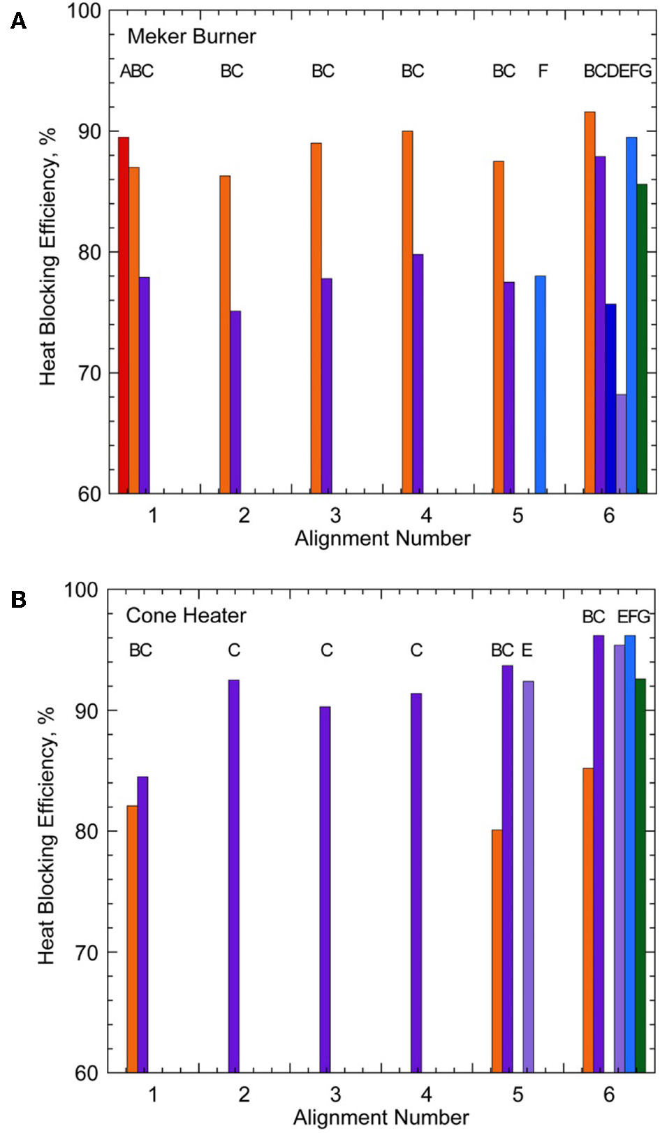
Effects of the layer alignment on the heat-blocking efficiency of double-layered aluminized materials in the (A) Meker burner and (B) cone heater. Assembly number (see Table 3), A-aramid/fiberglass, B-aramid/carbon/fiberglass, C, D, E, F-fiberglass, G-fiberglass (inner) and amorphous silica (outer); 1-fabric+fabric (exposed), 2-fabric+fabric/Al (exposed), 3-fabric/Al+fabric (exposed), 4-al/fabric+fabric, 5-fabric/Al+fabric/Al (exposed), 6-Al/fabric+fabric/Al (exposed).
Summary
In this work, the transient and steady-state thermal response characteristics have been determined for more than 20 multiple-layered fire blanket materials using a convective (Meker burner) or radiant (cone heater) heat source, independently. The findings are summarized as follows.
In addition to conventional thermal protective performance (TPP) ratings for protective clothing, the following two transient thermal response times and a steady-state heat-blocking efficiency (HBE) are introduced both convective and radiant heat sources in this study:
Fabric exposure time for the back side temperature to reach 300°C.
Fabric exposure time for the through-the-fabric transmitted heat flux to reach 13 kW/m2.
HBE = [1—(transmitted heat flux)/(incident heat flux)] × 100 (%).
The data base provides basic information required by the industry in a product development of structure protective fire blankets. The HBE data are particularly important.
Multiple-layered materials combinations demonstrated high thermal protective characteristics: for the double-layered, HBEs up to 92% for convection and 96% for radiation. Triple-layered blankets of thin fabrics do not improve significantly compared to double-layered blankets.
For convective incident heat flux, the heat loss by radiative emission from the high-temperature surfaces and the efficient thermal insulation by the blanket material are the primary heat transfer mechanisms for relatively high HBE's. For radiative incident heat flux, highly reflective aluminized materials result in exceptionally high HBE's.
As multiple-layered fire blankets become heavier and costlier, they may be more suitable for partial structure coverage (e.g., windows) or other high-temperature intense-exposure applications, e.g., protection of firefighters (fire curtains for bulldozers and fire engines), vehicles, and equipment.
Field Fire Experiments
Preliminary Experiments in Burn Rooms
In cooperation with Cuyahoga Community College's Fire Academy (Parma, Ohio), small-scale preliminary experiments have been conducted by placing two dollhouse-size wooden structures, covered with different fire blanket materials, in a burn room inside donated residential buildings during firefighter training sessions.
Figure 2A shows a house (L-shaped flat) used for firefighter training. The experiment was conducted by exposing two dollhouse-size wooden structures (0.31 m W × 0.31 m D × 0.41 m H, 19 mm (3/4”)-thick cedar walls and roof) to a wooden pallet/straw fire in a room inside the house. Each structure was wrapped with different fire blankets: metallic polyester coated amorphous silica (AAS1800) and pre-oxidized carbon fiber (CK-3) (see Table 1). The blankets were secured with staples using a manual staple gun. Each structure was equipped with three thermocouples (K type, 0.5 mm [0.020”] diameter stainless steel sheath, ungrounded) for measuring the temperatures of the blanket fabric outer (exposed) surface, wood outer surface (between the blanket and wood), and the wood inner surface. Figure 2B shows the covered wooden structures placed on sintered blocks surrounded by wooden pallets inside the house before fire. Figure 2C shows the wooden structure after fire exposure. Although the fire blankets were significantly damaged (scorched) and the wood charred, ignition of the structures is successfully prevented. Thus, the based on the success criteria definition, both fire blankets passed with a minimum success.
Figure 2
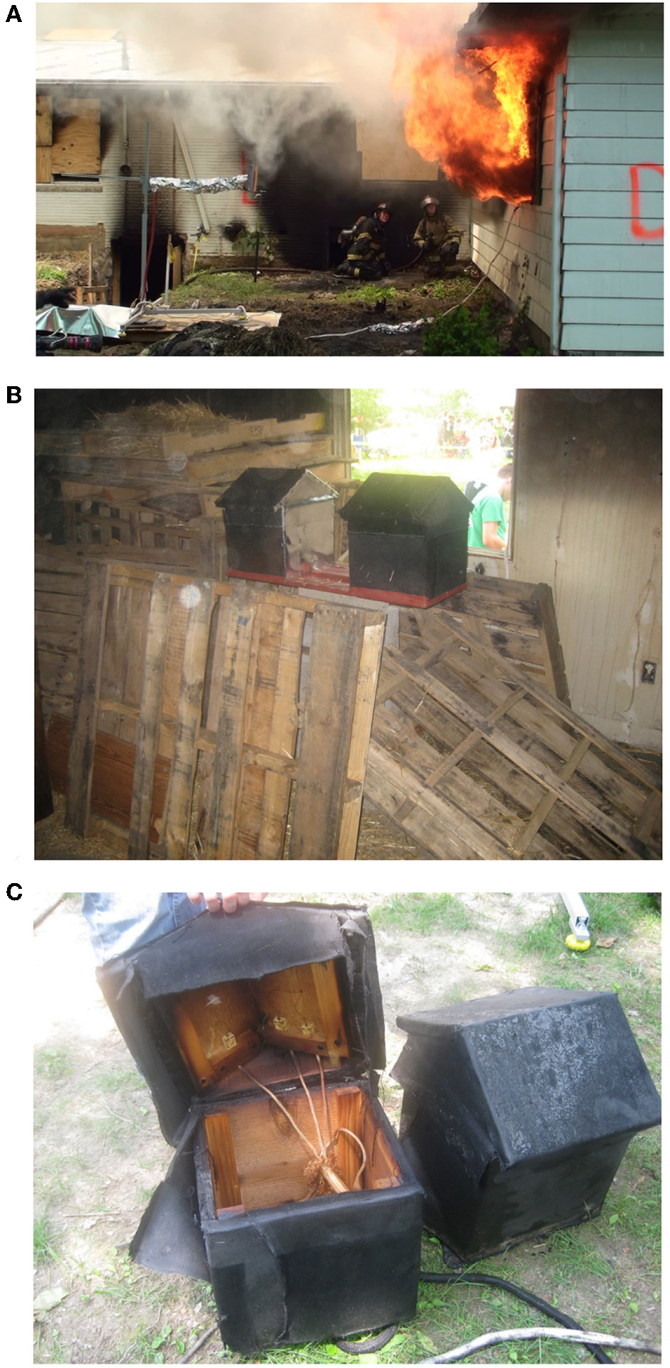
The burn-room experiment in Avon Lake, Ohio experiment. (A) The fire gushes through the window toward a temperature and heat-flux sensor stand (left), (B) the blanketed wooden model structures surrounded by palettes before ignition. Left: metallic polyester coated amorphous silica (AAS1800) and right: pre-oxidized carbon fiber (CK-3), and (C) the structures after fire exposure (left: CK-3 and right: AAS1800).
Figure 3 shows the temporal variations in the measured temperatures. Red and black curves are for metallic amorphous silica and pre-oxidized carbon, respectively. For the pre-oxidized carbon blanket, the fabric outer surface increased rapidly to ≈700°C in 120 s after exposure and increased more gradually to the maximum of ≈850°C at 400 s just before fire suppression by water began. Although the continuous operating temperature of pre-oxidized carbon was very high (1,427°C, see Table 1), the fabric was severely damaged and became brittle. The wood outer surface (between the blanket and wood) temperature was 100°C to 250°C lower than the fabric outer surface temperature. Therefore, the pyrolysis and charring of wood, which started at 200–300°C (390–570°F), occurred (see Figure 2C). The temperature of the wood inner surface increased gradually to the maximum of ≈200°C at 400 s.
Figure 3
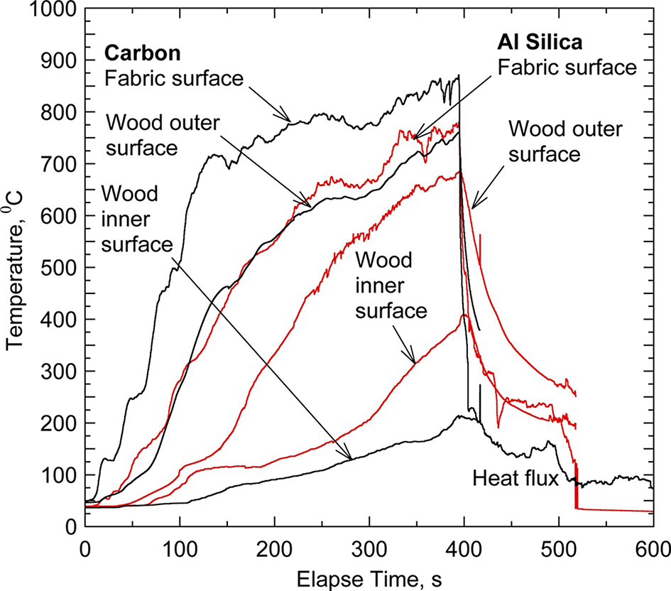
Temporal variations in the measured temperatures in the blanketed wooden structure. Red, aluminized amorphous silica; black, pre-oxidized carbon.
For the metalic amorphous silica blanket, the trend was similar to the pre-oxidized carbon case, but the fabric outer surface and wood outer surface temperatures were somewhat lower and reached ≈750°C and ≈650°C, respectively. The fabric outer surface temperature exceeded the melting point of aluminum (660°C), and the surface was severely damaged (see Figure 2C). However, the continuous operating temperature of base material (amorphous silica) was 980°C, and there was no significant damage on the fabric except discoloring. The wood inner surface temperature went up to the maximum of ≈400°C at 400 s. This result was consistent with the visual observation that the inner surface of the wood was more pyrolized for the silica fabric case. It was difficult to speculate the differences between the two different fabrics because the heat exposure conditions may be different. Note that, even though the fabric was damaged and the pyrolizing wood outer surface temperature exceeded 300°C and reached ≈750°C for both cases, flaming ignition was prevented because the fabric was in contact with the charring wood surface to block the oxygen penetration. By definition, the both fire blankets are judged as a “pass/minimum success.”
An additional burn-room experiment was conducted using the same fire blanket materials in a two-story house, which was burned down after the experiment and firefighter training. The effects of heat exposure and high temperature on the structures were very similar to the previous fire experiment. Again, the fire blankets were damaged and the wood charred, but ignition of the structures was prevented. This result suggested that it is critically important to secure the fire blanket in contact with the wood structure to keep oxygen in air from contacting with the high-temperature wood surface and thus to prevent flaming ignition.
Prescribed Burn Experiments in California
Experimental Approach
The field-fire experiments of fire blankets were conducted in prescribed wildland fires in Castaic, Los Angeles County, California, as a part of the live-burn testing operation for bull-douser operator protection and fire shelter testing hosted by the USDA Forest Service San Dimas Technology Development Center (FS SDTDC). The prescribed burn was administered by the Los Angeles County Fire Department. A satellite map of the live burn sites is presented as Supplementary Figure 1. The burn areas are on slopes facing north (darker shades) and the observation viewpoint areas are located on the south-facing slopes across the valley. The distances between the test structures and the view areas are ≈229 m (≈750 ft) for Burn #1 and ≈153 m (≈500 ft) for Burn #2. The fuel is chaparral, a special plant community characterized by drought-hardy, woody shrubs, shaped by a Mediterranean-type climate (summer drought, winter rain) and intense, infrequent wildfires (Anon, 2012).
For each burn, four instrumented wall-and-roof wooden structures are used. A sketch of the wall-and-eave wooden structure is included as Supplementary Figure 2. The wall (1.22 m [4 ft] width × 1.83 m [6 ft] height) and roof (1.22 m [4 ft] width × 0.61 m [2 ft] length) are made of plywood sheathing (Lowe's, 12242, 19/32” thickness, pine rated) with cedar siding (Star Lumber, Winlock, WA; CSS3484, ¾” × 8' × 4') and plywood sheathing with cedar shingle roof panels (Star Lumber, 6C-RFP), respectively. The cedar siding and roof panel materials are the same kind with those for a full-size shed (see section Prescribed Burn Experiments in New Jersey).
Each structure is instrumented for heat-flux and temperature measurements. Two incident heat flux transducers (ITI Model HT-50, T-type thermocouple) are placed on the wall (near the edges of Panels #1/#2 and #3/#4 at 1.22 m [48”] height). A water-cooled through-the-fabric heat flux transducer (Medtherm 64 Series) and three K-type thermocouples (for the fabric's front surface, back surface, and the sheathing back surface temperatures at 1.22 m [48”] height) on each panel. The cooling water is circulated using two sets of a pump and a buried 18.9 L (5 gallon)-reservoir to the heat-flux transducers on Panels #1/#2 and #3/#4. The signals from the sensors are recorded at 10 Hz using a field data-acquisition system (National Instruments, CompactRIO, cRIO-9014) covered by an insulated stainless steel box. Photographic and video observations are made using a digital camera (Nikon D300s) at a distant viewing area across the valley. Two fire-box-protected video cameras are also installed nearby the structures by the USDA FS Missoula Technology Development Center (MTDC).
Materials
Each structure is wrapped with a different aluminized fire blanket material as shown in Table 4. The blankets are secured with staples using a manual staple gun. The materials of the base fabrics are fiberglass, amorphous silica, and aramid/fiberglass/pre-oxidized carbon composite as shown in Table 1. The laboratory performance test results for single and double-layer fire blankets are included in Tables 2, 3, respectively. The fire blankets, which exhibited relatively high performance (mainly HBE values) among the 50 single-layer fabrics reported previously (Takahashi et al., 2014), are selected for the fire exposure tests. All fire blanket tested (Table 4) are single-layer, except for the USFS new fire shelter (assembly #G6 in Table 3) used for Panel #1 in Burn #1 and the double fiberglass with aluminized polyester for Panel #3 (assembly #D6 in Table 3) in California. Since the single fabrics performed well in Burn #1 as described below, double-layer blankets are not used in proceeding fire exposure experiments.
Table 4
| Panel #a or locationb,c | Code name | Fabric description |
|---|---|---|
| Castaic, California | ||
| Burn #1 | ||
| 1a | FS-NEW-I and FS-NEW-O | Fiberglass (USFS new fire shelter, inner shell), aluminized coating inside + amorphous silica (outer shell), aluminized coating outside |
| 2 | SW-HD | Fiberglass (structure wrap, heavy duty), aluminized coating |
| 3 | 1299-074 double | Fiberglass, aluminized polyester coating inside and outside |
| 4 | AFLPN1500 | Aramid-carbonized acrylic blend (non-woven)/aramid outer layer (woven)/fiberglass core (woven), aluminized PET coating |
| Burn #2 | ||
| 1 | FS-NEW-O | Amorphous silica (USFS new fire shelter, outer shell), aluminized coating |
| 2 | SW-STD | Fiberglass (structure wrap, standard duty), aluminized coating |
| 3 | AGL2025 | 100% fiberglass, aluminum foil coating |
| 4 | 1025 | Fiberglass, aluminized polyester coating |
| Warren Grove, New Jersey | ||
| Burn #2 | ||
| A/Bb (S/W)c | AGL2025 | 100% fiberglass, aluminum foil coating |
| B/C (N/W) | SW-HD | Fiberglass (structure wrap, heavy duty), aluminized coating |
| C/D (N/E) | FS-NEW-O | Amorphous silica (USFS new fire shelter, outer shell), aluminized coating |
| D/A (S/E) | 1025 | Fiberglass, aluminized polyester coating |
Fire blanket materials tested in prescribed burns.
From left to right on the back side.
A-B-C-D (wall identifier): clockwise A (entrance), B, C, and D. Wall A faces south.
N-E-S-W (geographic directions): north (N), east (E), south (S), and west (W).
Results and Discussion
Burn #1
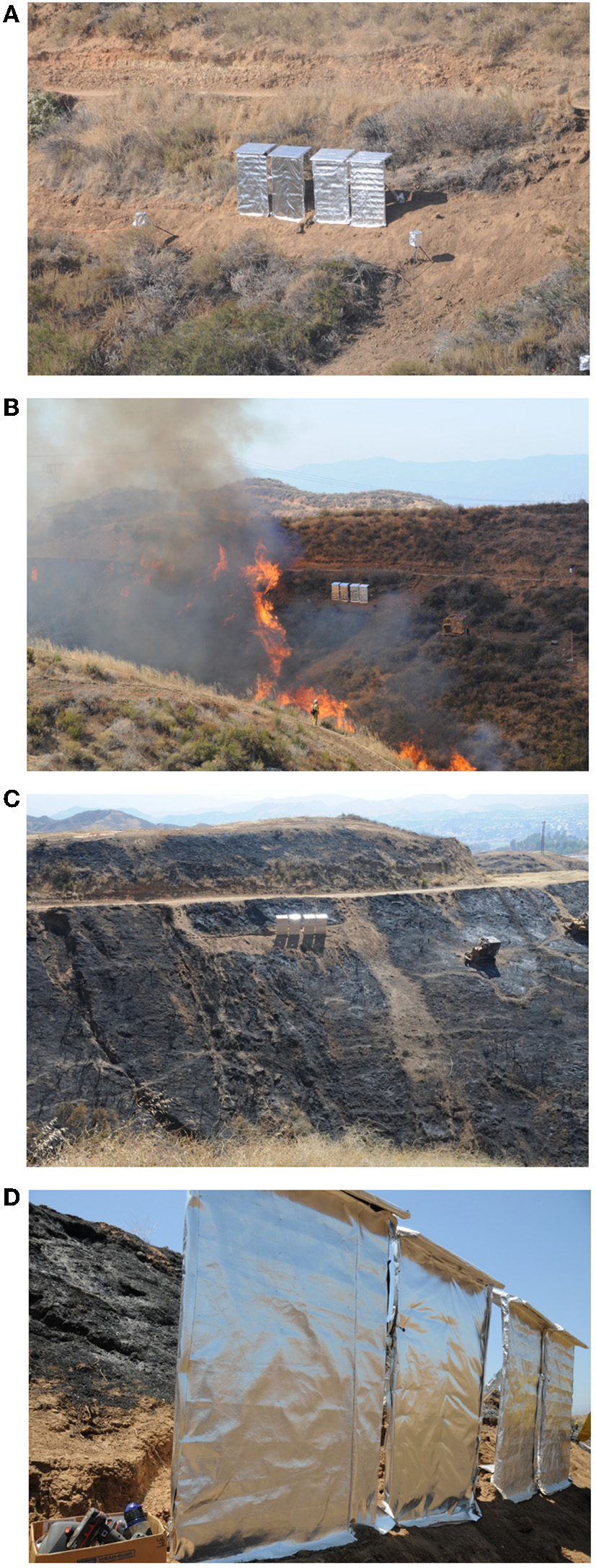
Figure 4A shows four wall-and-eave structures covered with fire blankets standing ≈1.8 m (6 ft) away from the edge of the vegetation on a steep slope before Burn #1. Two heat-shielded video camera boxes are also seen besides the structures. There is a fire break line (no vegetation) of 3 m to 6 m (10 to 20 ft) width on the slope on the right hand side (west) of the structures. The fire, started at the east end along the bottom of the valley, climbed up the slope and spread westward. Figure 4B shows the fire front approaching the wall-and-eave structures. Figures 4C,D show the wall-and-eave structures after Burn #1. Both the fire blankets and the wood parts (not shown) exhibited no sign of damage. Therefore, by definition, the all four fire blankets are judged as a “pass/complete success.”
Figure 4
Photographs of Burn #1. (A) Four wall-and-eave wood structures covered with different fire blankets (see Table 4) standing on the slope and two protected camera box stands on both sides, (B) the fire front is climbing up the slope and approaching the structures, and (C,D) the undamaged wood structures with fire blankets after the prescribed burn.
Figure 5A shows the measured incident heat flux (and the transducer temperature) on the wall (near the edges of Panels #1/#2 and #3/#4) in Burn #1. For Panels #1/#2 and #3/#4, the incident heat flux peak at ≈10 kW/m2 and ≈15 kW/m2, respectively, and the exposure duration was ≈150 s for both locations. Figure 5B shows the measured incident and through-the-fabric heat fluxes, fabric front-side (Tfront) and back-side (Tback) surface temperatures, and the plywood sheathing back-side temperature (Tinside) for Panel #1. The fabric front and back surface temperatures varied in response to the incident heat-flux peaks (when a flare approached occasionally). The fabric front surface temperature peak only up to 120°C, and the wood back surface (and inside) temperature were kept <80°C. The measured heat-flux and surface temperature values were lower than the critical heat flux and ignition temperature of wood (13 to 20 kW/m2 and ≈300°C). The intensity and duration of heat exposure on the structures were weaker than expectation. A plausible explanation for this result was due to the relatively scarce vegetation on the slope, the bare (no-fuel) fire line along the slope, the cleaned front gap in Burn #1 (see Figure 4C) as well as the steep slope, which caused fast flame spread and short fire exposure. Thus, more intense and longer heat exposure was desired to test the fire blankets' performance.
Figure 5
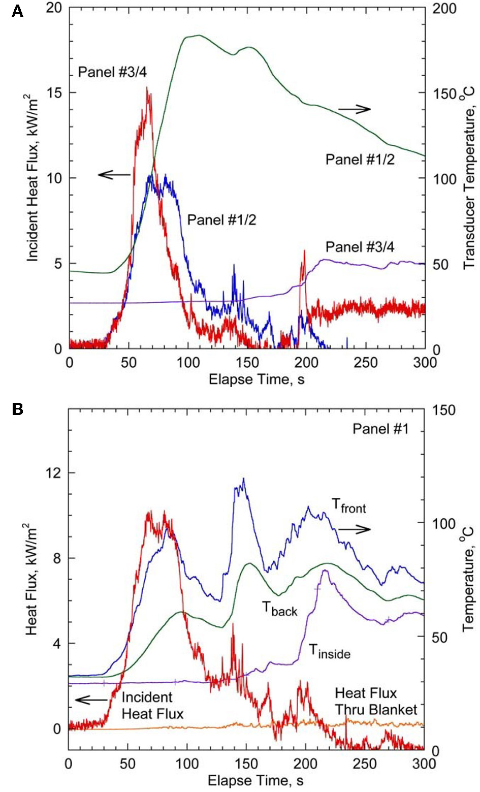
Measurements in Burn #1. (A) The incident heat flux and transducer temperature at the wall locations between the edges of Panels #1/#2 and #3/#4, and (B) incident and through-the-fabric heat fluxes and temperatures at the fabric front and back surfaces and the back (inside) of the wood sheath of Panel #1.
Burn #2
Because the Burn #1 did not leave any obvious damage to the blankets and wood panels, additional tree branches and bushes were piled up in front of the structures in Burn #2 to increase the fire exposure. Figure 6A shows four wall-and-eave structures covered with different fire blankets before Burn #2, standing on a slope shallower than that of Burn #1. The fire was ignited on the bottom of the valley and reached the structure location in several minutes. Figures 6B,C show the wall-and-eave structures being exposed to a blaze for a few minutes. Figure 6D shows four undamaged protected structures (right) in contrast to an nearly unprotected (covered with coarse “chicken” wire mesh) wooden structure ≈6 m (≈20 ft) away (left), which was burning for a relatively long period (≈20 min) after the fire front has passed. Video footages that cover the times corresponding to Figures 6C,D are presented as Supplementary Videos 1, 2, respectively.
Figure 6
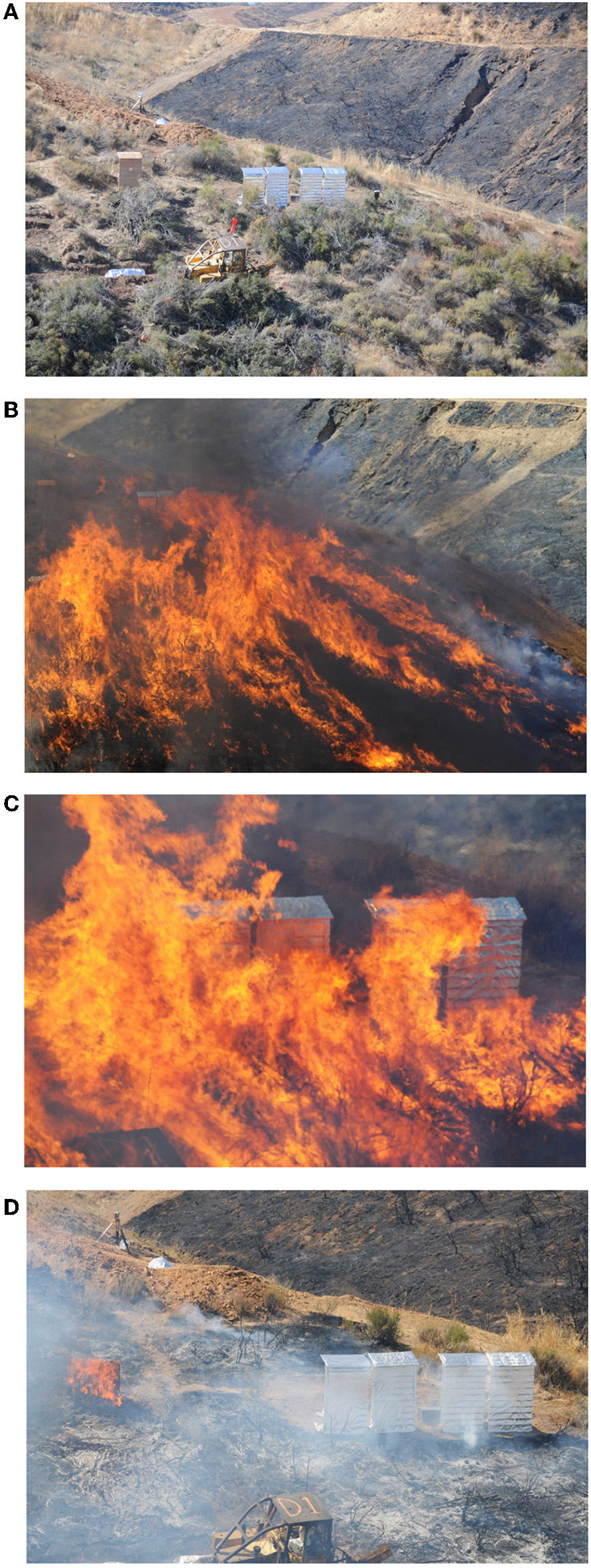
Photographs of Burn #2. (A) Four wall-and-eave wood structures covered with different fire blankets (center; see Table 4) and another wood structure covered with wire mesh screen (left) standing on the slope (B,C), the fire front is approaching and engulfing the structures, and (D) the undamaged four wood structures (right) and the burning wire mesh-covered structure (left) after the prescribed burn (see Supplementary Videos 1, 2).
This Burn #2 result demonstrated the impressive performance of fire blankets in a real wildland fire scenario. Figures 7A,B show all four undamaged fire blankets and the wood panels before and after removing the blankets after the burn. Figure 7C shows a coin-size scorched spot on the bottom left corner of the leftmost Panel #4. This burn mark seemed to happen as a result of hot-gas penetration through a small gap between two fire blankets, which were secured with staples. This incidence suggests that although the aluminized fire blankets are impermeable, it is crucially important to seal gaps between fire blankets to avoid hot-gas or firebrand penetration. Nonetheless, by definition, all four fire blankets are judged as a “pass/complete success.”
Figure 7
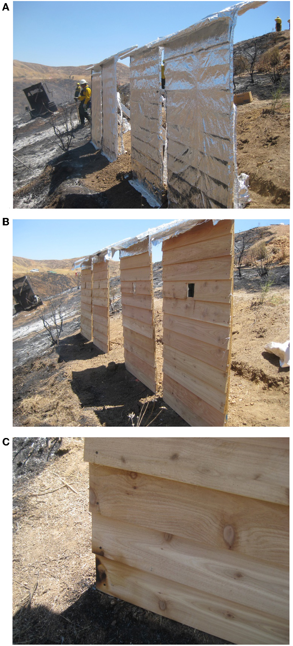
Photographs of the structures after Burn #2. (A) All four different fire blankets were undamaged and (B) the wood panels are also undamaged, except for (C) a coin-size scorching area on the bottom left corner of the leftmost Panel #4.
Figure 8A shows the measured heat fluxes and temperatures in the wooden wall structure (Panel #3). The plots include the incident heat flux, incident heat flux transducer temperature (Tinc.HFT), through-the-blanket heat flux, fabric front-side (Tfront) and back-side (Tback) surface temperatures, and the plywood sheathing back-side temperature (Tinside). The heat exposure on the blanketed structures (Panels #3 and #4) lasted ≈5 min with a peak incident heat flux of ≈20 kW/m2 and Tinc.HFT peaked at 300°C. The heat exposure (level and duration) was greater than those in Burn #1 (Figure 5A) and comparable to the threshold for ignition of woods (13 to 20 kW/m2 and ≈300°C). Tfront rose up to peaks of 200°C, while Tback and Tinside remained low (<80°C), thereby protecting the wood structure. The heat exposure for Panels #1 and #2 (not shown) was much smaller. This observation was consistent with video observations showing more fire attack on Panels #3/#4 compared to #1/#2 (see Figure 6C and Supplementary Video 1).
Figure 8
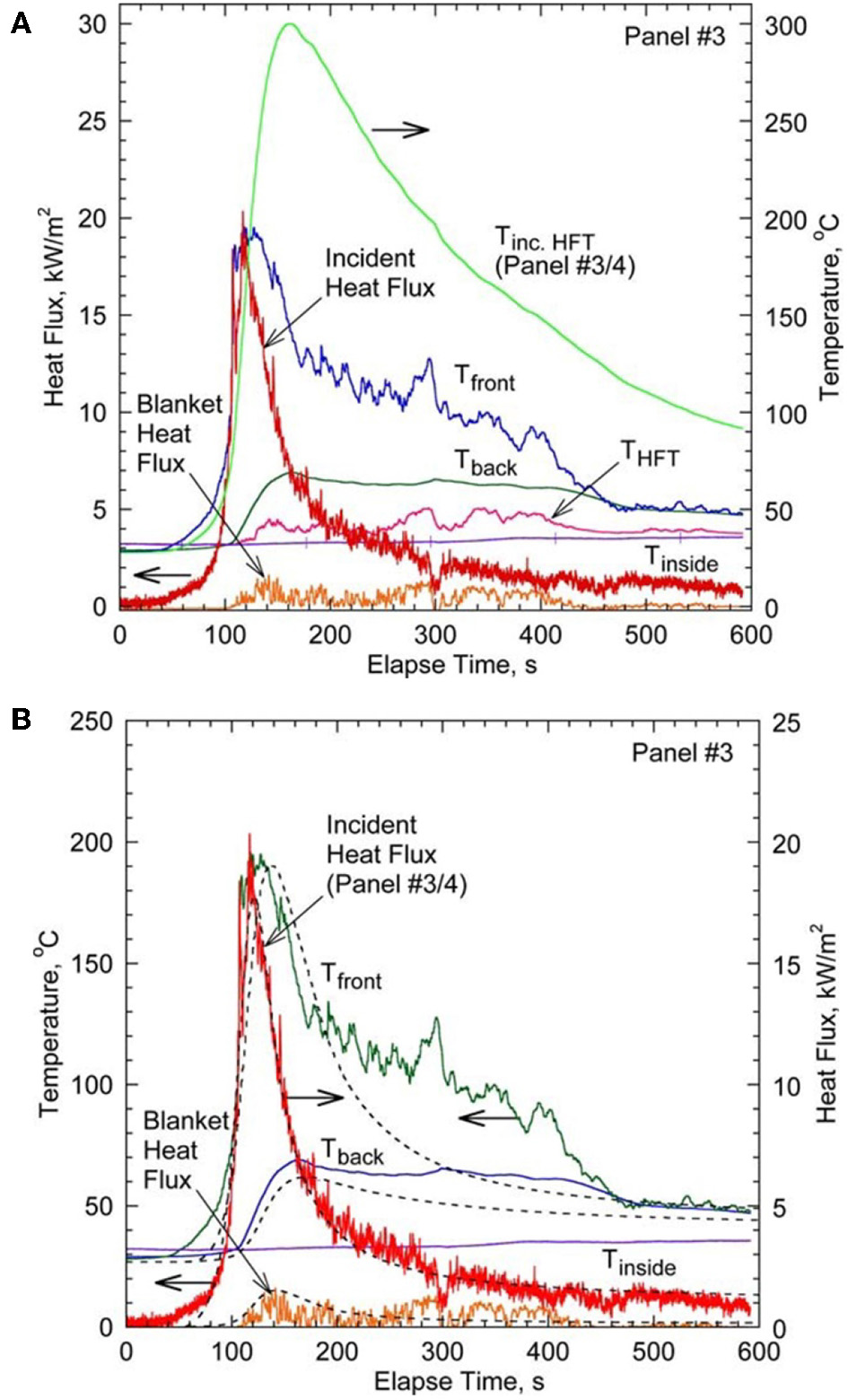
Measurements and calculations in Burn #2. (A) Measured incident and through-the-fabric heat fluxes, and temperatures at the fabric front and back surfaces and the back (inside) of the wood sheath of Panel #3, and (B) calculated (dashed curves) fabric front and back surfaces and through-the-fabric heat flux based on the prescribed incident heat flux from the experiment.
Figure 8B shows the numerical results based on the method previously used (Hsu et al., 2011) for Panel #3 as well (dashed). Note that the applied heat source as a function of time is prescribed according to the measured incident heat flux, and the simulated through-the-blanket heat flux and Tback are respectively obtained at x = Lf and x = Ls in the model. It is found that using 70% of incident heat flux from radiation (30% from convection) has a good comparison with the experimental data. The numerical model based on the laboratory experiment successfully captured the general trend in the thermal response of the structure in a real wildland fire scenario.
Prescribed Burn Experiments in New Jersey
Experimental Approach
The large-scale proof-of-concept fire exposure experiments for fire blankets were conducted in the Pine Barrens in Warren Grove, New Jersey, as a part of the controlled-burn fuel management operation regularly performed by the New Jersey Forest Fire Service (NJFFS) during late fall through early spring to reduce accumulated fuels. Although two burns were conducted over the 2 year period, the post-rain wet vegetation conditions prevented the development of a full-fledged surface-to-crown fire in Burn #1. Therefore, the only results of Burn #2 are presented here. The prescribed burn activities were based on the NJFFS Coyle Field, where a test shed was built. The shed was airlifted by a helicopter from the Coyle Field to the burn site 15 km (9.3 mi) prior to the test day. The shed was placed in a 9 m × 9 m (30 ft × 30 ft) cutout area in the Pitch Pine forest.
A satellite map of the live burn sites in Warren Grove, New Jersey is presented as Supplementary Figure 3. The map illustrates the prescribed burn strategy in the experiment. Two blocks directly east of the block where the shed was place were burned earlier to contain the fire within the shed block. Two other blocks east were burned the year before. The prescribed burn was planned as a west wind driven “head fire,” and keep sending the head fire into the flanks to eliminate any chance of escape. The total area burned for the day was 890 m2 (220 acres). The fuel is Pitch Pine (4.5 to 9 m height) and underbrush (scrub oak). To make intense heat exposure more evenly distributed around the shed, additional fuels (pine branches) are placed 1.5 m to 3.3 m (5 ft to 10 ft) away from the shed.
An instrumented wooden shed (Home Depot, Star Select Cedar Shed, Model 100659823, 3.1 m W × 2.4 m D × 3.3 m H [10 ft × 8 ft × 11 ft], with cedar bevel siding, cedar roof shingles and additional solid pine sheathing) was used as the test structure. The shed structure is instrumented for heat-flux and temperature measurements. Six incident heat flux transducers (ITI Model HT-50, T-type thermocouple), eight water-cooled through-the-fabric heat flux transducers (Medtherm 64 Series), and forty K-type/T-type thermocouples are placed on the walls and the roof. The cooling water is circulated through the heat flux transducers using two pumps from two 18.9 L (5 gallon)-reservoirs. A hemispherical cup anemometer (Met One 034B) and a weather tracker (Kestrel 4000) are placed on a pole 3.3 m (10.8 ft) and 2 m (6.6 ft), respectively, above the ground. The signals from the sensors are recorded at 10 Hz using a field data-acquisition system (National Instruments, CompactRIO, cRIO-9014 and two notebook computers) in a steel box buried outside the shed. Two digital HD video cameras (Sony HDR-CX110) located in the northeast and southwest of the shed are set in heat-shielded steel boxes. The sensors and data system were tested in the prior experiments.
Materials
The structure (shed) is wrapped with four different aluminized fire blanket materials listed in Table 4. The blankets are secured with staples using a manual staple gun. From a top view perspective, each blanket covers a quarter section of the shed around the corner of the walls and a quarter part of the roof. All fire blankets are selected from ones used in the fire-exposure experiments in California, except that only single outer layer of the USFS new fire shelter (FS-NEW-O) is used instead of the original double-layer ensemble. The materials of the base fabrics are fiberglass or amorphous silica as listed in Table 1. The laboratory performance test results for single-layer fire blankets are included in Table 2.
Results and Discussion
The underbrush was ignited by drip torches over 91 m (300 ft) along the west fire line (see Supplementary Figure 3) to gain the best possible chance of success yet limit the amount of head fire ignited at one time. The incipient fire after ignition quickly developed into ground-to-crown fire (see Supplementary Figure 4). The fire front spread at ~9 to 12 m/min to reach the east fire line in ≈20 min. One of two high-definition video cameras, facing the incoming fire front, captured successfully the sequence of event while the fire front was approaching, engulfing, and passing the shed. A 4 min video footage (2 min before and after the fire front arrival) is presented as Supplementary Video 3 and the selected video images are shown in Figure 9.
Figure 9
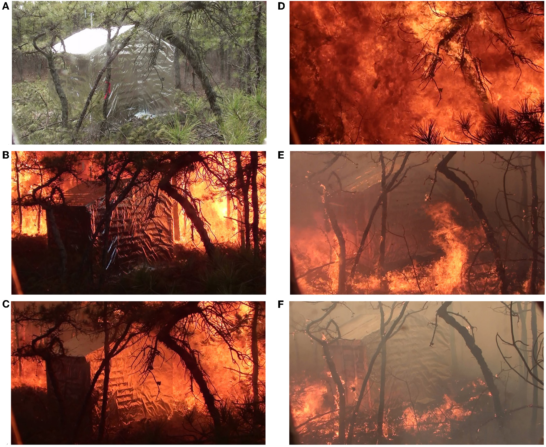
Video images from the northeast side captured the fire front approaching from the east side and passing over the blanketed wood structure in a few minutes (see Supplementary Video 3). (A) The fire front is still ∽20 m away, (B) approaching, (C) arriving, (D) engulfing, (E) passing the shed, and (F) additional fuels continue to burn.
The video camera was located ≈6 m (≈20 ft) northeast of the shed, thus viewing walls “C” and “D” (see Table 4). Another video camera located ≈10 m (≈30 ft) southwest of the shed could not capture the event because the quartz window of the box was covered with soot and firebrand debris soon after the fire front arrival. A plastic iris inside the lens (of both cameras) locked open after radiant heat exposure fused vanes together, even it was protected by the quartz window. A scene when the fire front was still ≈20 m away (Figure 9A), the shiny blanketed shed and trees with green leaves are seen under ordinary sunshine. As the fire front approached from the west side (wall “B”), bright flame became visible (Figure 9B). A shower of firebrands and spotting ignition of surface vegetation were observed on the ground. As the fire front reached the shed (Figure 9C), the westerly wind became stronger as evident from the fast rotating cup anemometer. Figure 9D shows the fire engulfing the shed and the burning branches moving around. The camera box supporting pole flexed backward by the wind so that the shed disappeared from the field of view temporarily. As the fire front moved away from the shed (Figure 9E), the camera pole returned to the original position and the branches piled around the shed remained burning (Figure 9F). The video camera also recorded the audio signal from the firebrands hitting the camera box supporting pole during the fire front passing.
Figure 10 shows post-fire photographs revealing damage to the fire blankets and wall surfaces of the wooden structure. A left half of the entrance wall “A” (Figures 10A,B) and a right half of the wall “B” (Figures 10C,D) and a quarter of the roof were covered with aluminum foil laminated fiberglass fabric (see Table 4). The aluminum foil was partially peeled and broken away on wall “A,” but there was no damage on the wood. The blanket might have been damaged partially when firefighters broke in through the door after the burn. A left half of the wall “B” (Figures 10C,D) and a right half of the wall “C” (Figures 10E,F) were covered with a heavy-duty structure wrap fabric. There was no apparent damage on both the blanket and wood. A left half of the wall “C” (Figures 10E,F) and a right half of the wall “D” (Figures 10G,H) were covered with aluminum foil laminated amorphous silica. For wall “C,” there was no apparent damage on both the blanket and wood, except that the blanket wrinkled. However, for wall “D,” the aluminum foil burned away and the wood was charred. A left half of the wall “D” (Figures 10G,H) and a right half of the wall “A” (Figures 10A,B) were covered with aluminized polyester laminated fiberglass fabric. The fire blanket burned away, and a part of the wooden wall burned through. Firefighters extinguished the fire on wall “D” by entering the shed and gently spraying water shortly after the controlled burn. The fire blankets and the wood shingle surfaces of the roof were completely intact despite the hot-gas and firebrand exposure.
Figure 10
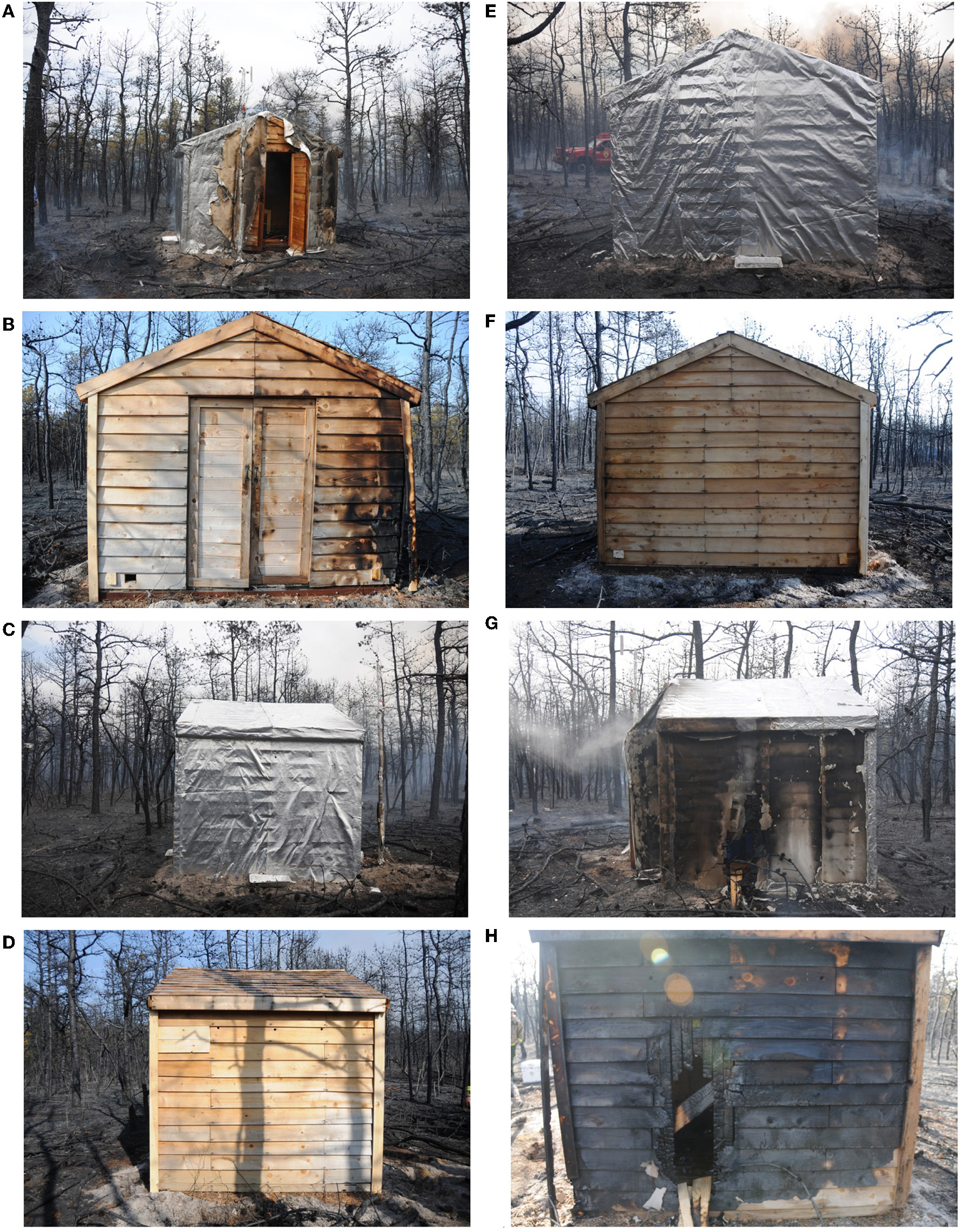
Fire blanket and wood structure damage after the prescribed burn (see Table 4 for the blanket materials). (A,B) Wall “A” facing south, (C,D) Wall “B” facing west, (E,F) Wall “C” facing north, and (G,H) Wall “D” facing east.
Based on the success criteria (see section Limitations and Success Criteria) and the observations above, the performance of the fire blankets tested are categorized as: AGL2025 (on walls “A”/”B”), pass/complete success; SW-HD (on walls “B”/”C”), pass/complete success; FS-NEW-O (on walls “C”/”D”), pass/minimum success; and 1,025 (on walls “D”/”A”), fail. Note that the success criteria do not include the nature of fire exposure. Although all blankets were exposed to the same fire, the severity of fire exposure was different, depending on the location in the shed, which affected the incident heat flux, heat transfer modes—radiation, convection, and conduction, gas temperature, wind speed/direction, firebrand, and fuel loading; and most importantly, the exposure duration. For example, wall “D” was located behind the approaching fire front, which caused the wake of the wind direction and relatively low-speed area with a long residence time. The fire lasted a longer time behind the shed, compared to the front side, as evident from the video (Supplementary Video 3) and images (Figures 9E,F). Moreover, the fire blanket 1025 performed well in the laboratory experiment (see Table 2) but failed in the fire exposure probably due to the burn out loss of the combustible reflective layer and the long lasted direct flame contact. The experiment including both pass and fail results is valuable to demonstrate the potential and limitation of the present approach for the structure protection by fire blankets.
The data acquisition systems started to record data before the ignition along the west fire line (Supplementary Figure 3). However, one of the data acquisition systems stopped prematurely and the incident and through-the-fabric heat flux, blanket temperature, and cup anemometer data were not recorded during the fire exposure. Fortunately, the weather tracker data were acquired successfully. Figure 11A shows the air temperature, pressure, relative humidity, and wind speed at 2 m (6.6 ft) above the ground near the shed entrance. Figure 11B shows the data collected 1.4 m (4.6 ft) above the ground at the road side near the ignition point. The weather condition at the shed before the fire front arrival were sunny/partly cloudy, 22°C (71.6°F), relative humidity of 40%, pressure of 1,009 hPa (14.6 psi), generally westerly wind: 1 to 2 m/s (2.2 to 4.4 mph). As the fire front arrived at the shed (arbitrary elapse time: 1,000 s), the air temperature rose rapidly above the upper measurement limit (clipped at 155°C [311°F]; blackout), the pressure slightly decreased, and the relative humidity dropped. The wind speed vanes meted and quit working as soon as the fire front arrived. As the fire front moved away from the shed, these values except the wind speed recovered gradually toward the initial values in approximately 10 min. The high-temperature blackout period (>155°C) was approximately 50 s. It is consistent with the time period required for the fire front with a spread rate of 9 to 12 m/min to advance 7.5 to 10 m.
Figure 11
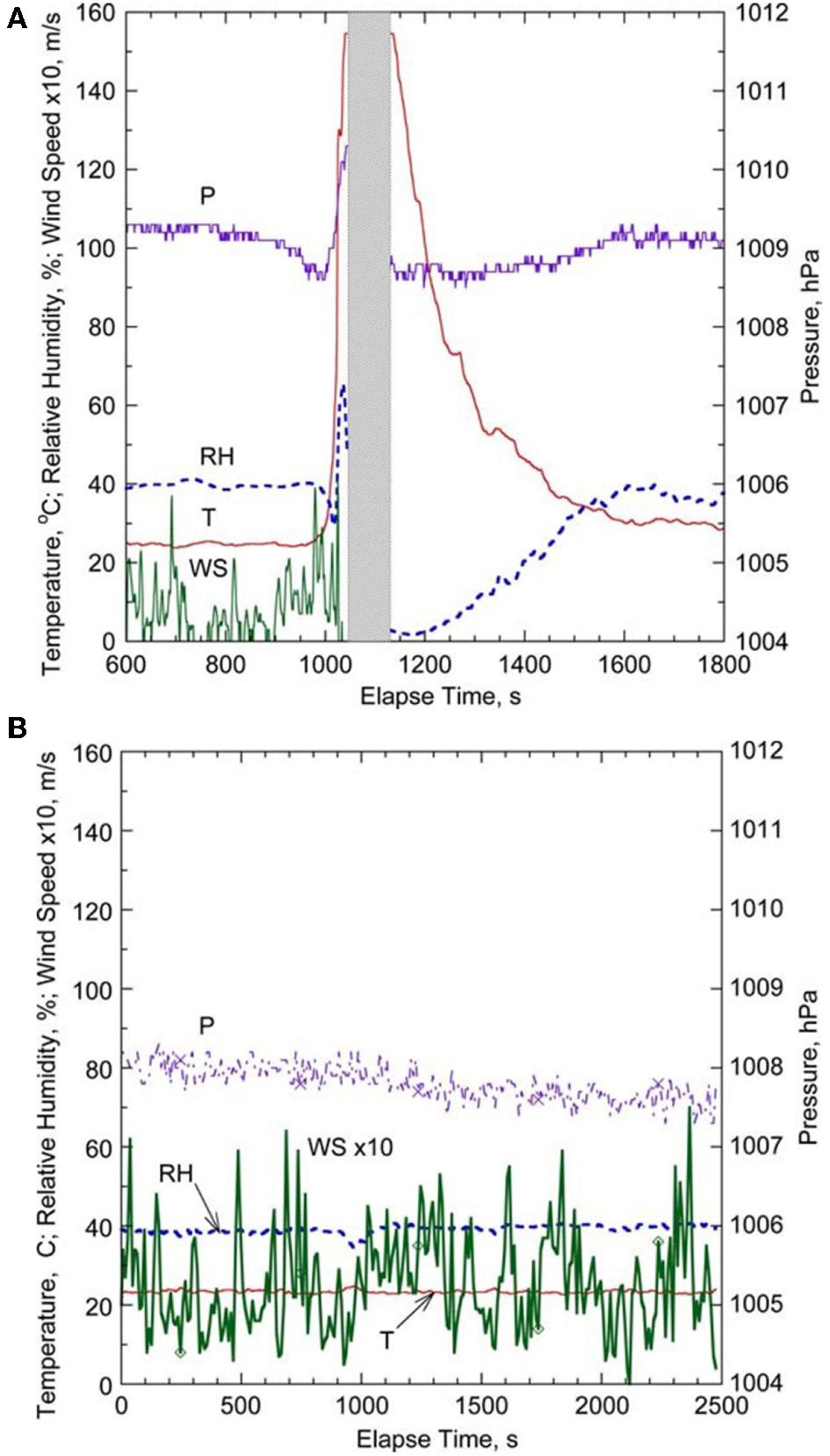
Measured air temperature, pressure, relative humidity, and wind speed. (A) At 2 m (6.6 ft) above the ground near the structure entrance (see a cup anemometer in Figure 9A) and (B) at 1.4 m (4.6 ft) above the ground at the roadside of the west fire line.
Summary
The proof-of-concept experiments, conducted by exposing various fire-blanket-protected wooden structures to realistic fires from burn room to full-scale prescribed burns, have demonstrated both remarkable performance and limitations of the structure protection method using fire blankets. In real fires, the level of heat exposure intensity and duration can vary widely depending on actual WUI fire scenarios and the situation of the structure surroundings. The present field fire experiments have provided valuable information on different cases where the heat exposure vary from relatively low intensity and short duration to severe conditions, thus causing no damage to complete destruction on the fire blankets and structures. In addition, a simple theoretical model is proved to be useful in capturing the trend of the transient response of the blanketed structures to a prescribed incident heat flux input.
The present field fire test results suggest that it is more likely that relatively thin (<1 mm) aluminized fire blankets can protect wooden structures if the heat exposure (heat-flux intensity, air temperature, etc.) does not destroy the aluminized layer and the duration is relatively short (<10 min). The aluminized polyester (PET) film is likely to burn and the aluminum foil laminate tends to peel (due to burning of the adhesive with low temperature resistance, i.e., 148°C) and burn under high heat exposure. If a higher-temperature resistant reflective layer is developed, the performance of fire protective blankets can be improved significantly. Although amorphous silica has a high continuous operating temperature (980°C, see Table 1), fiberglass (540°C) may perform properly if the reflective layer keeps the base material temperature sufficiently low. Additional experiments are needed for longer heat exposure period, which plays a critical role in the structure-to-structure ignition in high housing density areas.
Conclusions
The performance of fire blankets to block heat has been investigated experimentally in the laboratory and prescribed wildfires. Two-layer thin fabric assemblies blocked up to 92% of the convective heat and up to 96% of the radiation (with an aluminized surface). Multiple layers (or thicker single fabric) increase the heat-blocking efficiency by enhanced insulation against the convective heat exposure. On the other hand, multiple layers do not improve the performance against the radiation because the reflection and emission heat loss from the high-temperature front surface dominate the heat transfer mechanism. The series of proof-of-concept experiments provided valuable insight into the capabilities of fire blankets. The experiments demonstrated both successful performance and limitations of thin fire blanket materials by covering the conditions of all success criteria: “pass/complete success,” “pass/minimum success,” and “fail.” The best performed fire blankets may be able to protect building structures if the heat exposure is relatively short (<10 min). This conditions would happen when a wildfire front passes an isolated structure, e.g., a historic cabin. If the heat exposure continues, the fire blanket may more likely to be deteriorated or destroyed, while the building materials are being pyrolyzed and failed eventually. This situation would be the case for the structure-to-structure ignition. Therefore, for longer exposures (10 s of minutes to more than an hour), better fire blankets (materials, layer assemblies, etc.) would be needed. The key success factors in protecting the WUI structure are (1) the fire blanket's heat-blocking capability, (2) endurance under severe heat-exposure and high-wind conditions, and (3) proper installation to prevent hot-gas and firebrand penetration. Therefore, additional studies are needed in the future in the areas of advanced material/layer developments, blanket deployment methods, and multi-structure protection strategies.
Statements
Data availability statement
The datasets generated for this study are available on request to the corresponding author.
Author contributions
The author confirms being the sole contributor of this article and has approved it for publication.
Acknowledgments
The author would like to thank valuable contributions to the project by Prof. James S. T'ien, Dr. Sheng-Yen Hsu (CWRU), Dr. Sandra L. Olson (NASA Glenn Research Center), Ted Huffman (Cuyahoga Community College, Fire Academy), Ralph Gonzales, Sam Wu, Ian Grob, Anthony Petrilli (USDA Forest Service, SDTDC and MTDC), and James Dusha (New Jersey Forest Fire Service). Assistance in conducting the experiment by undergraduate co-op students: Amber Abbott, Timothy Murray, Mallory Miller, Jason Williams, Jacob Teets, Brian Guzek, Margaret Rybach (CWRU), and Wyatt Ratliff (Stanford University) was acknowledged. Fire shelter materials and Supplementary Video 1 were provided by USDA FS MTDC. Some fabric samples were provided by Auburn Manufacturing, Inc.
Conflict of interest
The author declares that the research was conducted in the absence of any commercial or financial relationships that could be construed as a potential conflict of interest.
Supplementary material
The Supplementary Material for this article can be found online at: https://www.frontiersin.org/articles/10.3389/fmech.2019.00060/full#supplementary-material
Footnotes
1.^Certain commercial equipment, instruments, or materials are identified in this article to adequately specify the procedure. Such identification does not imply recommendation or endorsement by the author or CWRU, nor does it imply that the materials, equipment, or materials are necessarily the best available for the intended use.
References
1
AhrensM. (2010). Brush, Grass, and Forest Fires. National Fire Protection Association, NFPA No. USS89.
2
AlbiniF. A. (1986). Wildland fire spread by radiation – a model including fuel cooling by natural convection. Combust. Sci. Technol.45, 101–113. 10.1080/00102208608923844
3
AndersonW. R.CatchpoleE. A.ButlerB. W. (2010). Convective heat transfer in fire spread through fine fuel beds. Int. J. Wildland Fire19, 1–15. 10.1071/WF09021
4
Anon (2006). Building and Fire Research Laboratory Activities, Accomplishments and Recognitions. NIST SP 838-19, National Institute of Standards and Technology, p. 23.
5
Anon (2009). Wildland Fire Shelter: History and Development of the New Generation Fire Shelter, presented by the Interagency Fire Shelter Task Group. Available online at: http://www.fs.fed.us/td/programs/fire/documents/shelhist.pdf (accessed May 29, 2019).
6
Anon (2012). The Chaparral. The California Chaparral Institute. Available online at: http://www.californiachaparral.com/
7
Anon (2018). It's a Wrap! How the Forest Service Protects Historic Structures from Fires. Active NorCal. Available online at: https://activenorcal.com/its-a-wrap-how-the-forest-service-protects-historic-structures-from-fires/ (accessed May 29, 2019).
8
Anon (2019). Protecting Homes, Cabins, and Historic Landmarks From Wildfires-With No Water. Firezat Inc. Available online at: https://www.firezat.com/ (accessed May 29, 2019).
9
ANSI/FM 4950 (2007). American National Standard for Evaluating Welding Pads, Welding Blankets and Welding Curtains for Hot Work Operations. FM Approvals LLC.
10
ASTM D 4108 (1982). Standard Test Method for Thermal Protective Performance of Materials for Clothing by Open-Flame Method. American Society for Testing and Materials.
11
ASTM D 4151 (2001). Standard Test Method for Flammability of Blankets. American Society for Testing and Materials.
12
ASTM E 1354 (2002). Standard test Method for Heat and Visible Smoke Release Rates for Materials and Products Using an Oxygen Consumption Calorimeter. American Society for Testing and Materials.
13
ASTM F 1939 (2007). Standard Test Method for Radiant Heat Resistance of Flame Resistant Clothing Materials. American Society for Testing and Materials.
14
ASTM F 1989 (2005). Standard Specification for Cooking Fire Suppression Blankets, 2005 Edn. American Society for Testing and Materials.
15
BabrauskasV. (2001). Ignition of Wood: A Review of the State of the Art, in Interflam 2001. Interscience Communications Ltd, London, pp. 71–88.
16
BackusP. (2013, May 19). U.S. Forest Service Trains Group on how to protect historic buildings from wildfire. Missoulian. Available online at: https://missoulian.com/news/state-and-regional/u-s-forest-service-trains-group-on-how-to-protect/article_e267603c-c0f1-11e2-9ce6-0019bb2963f4.html (accessed May 29, 2019).
17
BallingerV. R. (1973). Fire Protection Apparatus for a Building. U.S. Patent, No. 3715843. Alexandria, VA: U.S. Patent and Trademark Office.
18
BrentK. M. (2012). Optimization of fire blanket performance by varying radiative properties (M.S. thesis). Cleveland, OH: Department of Mechanical and Aerospace Engineering, Case Western Reserve University.
19
British Standards BS 7944 (1999). Type 1 Heavy Duty Fire Blankets and Type 2 Heavy Duty Heat Protective Blankets (superseded withdrawn BS 6575:1985).
20
British Standards BS EN 1869 (1997). Fire Blankets (superseded withdrawn BS 6575:1985).
21
ButlerB. W. (2010). Characterization of convective heating in full scale wildland fires, in VI International Conference on Forest Fire Research, ed ViegasD. X. (Coimbra).
22
Cal Fire (2006). General Guidelines for Creating Defensible Space. State Board of Forestry and Fire Protection (BOF), California Department of Forestry and Fire Protection. Available online at: http://www.highsierrameadows.com/wp-content/uploads/2016/01/CalFire-Defensible-Space-1.pdf (accessed May 29, 2019).
23
Cal Fire (2018). List of California Wildfires. Available online at: https://en.wikipedia.org/wiki/List_of_California_wildfires (accessed May 29, 2019).
24
CalderwoodP. L.BrockJ. R.ChattawayA. (2006). Fire Blanket. U.S. Patent Application, Publication No. WO/2006/008514. Alexandria, VA: U.S. Patent and Trademark Office.
25
ChitrphiromsriP.KuznetsovA. V. (2005). Modeling heat and moisture transport in firefighter protective clothing during flash fire exposure. Heat Mass Transfer41, 206–215. 10.1007/s00231-004-0504-x
26
ChitrphiromsriP.KuznetsovA. V.SongG.BarkerR. L. (2006). Investigation of feasibility of developing intelligent firefighter-protective garments based on the utilization of a water-injection system. Numer. Heat TransferA49, 427–450. 10.1080/10407780500359869
27
CohenJ. D. (1999). Reducing the Wildland Fire Threat to Homes: Where and How Much? USDA Forest Service, General Technical Report No. PSW-GTR-173. Available online at: http://www.fs.fed.us/rm/pubs_other/rmrs_1999_cohen_j001.pdf (accessed November 26, 2018).
28
CohenJ. D.StrattonR. D. (2008). Home Destruction Examination: Grass Valley Fire, Lake Arrowhead, California. USDA Forest Service, Technical Paper, R5-TP-026b (Vallejo, CA). Available online at: http://www.fs.fed.us/rm/pubs_other/rmrs_2008_cohen_j001.pdf (accessed May 29, 2019).
29
CohenJ. P. (1991). A Site-Specific Approach for Assessing the Fire Risk to Structures a the Wildland/Urbanin Interface. GTR SE-69. USDA Forest Service, Ashville, NC, 252–256.
30
DavisW. D.DonnellyM. K.SelepakM. J. (2006). Testing of Portable Radios in a Fire Fighting Environment, NIST Technical Note 14774, National Institute of Standards and Technology.
31
DonnellyM. K.DavisW. D.LawsonJ. R.SelepakM. J. (2006). Thermal Environment for Electronic Equipment Used by First Responders, NIST Technical Note 1474, National Institute of Standards and Technology.
32
EvansD. D.RehmR. G.BakerE. S. (2004). Physics-Based Modeling for WUI Fire Spread – Simplified Model. Algorithm for ignition of structures by burning vegetation, NISTIR 7179. Available online at: https://www.gpo.gov/fdsys/pkg/GOVPUB-C13-9b91be4e9e8024979f4c8e766261d6f5/pdf/GOVPUB-C13-9b91be4e9e8024979f4c8e766261d6f5.pdf (accessed May 29, 2019).
33
EvartsB. (2019). Fire Loss in the United States During 2018. NFPA J. 113, 76–83.
34
FinneyM. A.CohenJ. D.GrenfellI. C.YedinakK. M. (2010). An examination of fire spread thresholds in discontinuous fuel beds. Int. J. Wildland Fire19, 163–170. 10.1071/WF07177
35
FloydA. (1997). Fire Resistant House Cover. U.S. Patent, No. 5608992. Alexandria, VA: U.S. Patent and Trademark Office.
36
FrankmanD.WebbB. W.ButlerB. W. (2010). Time-resolved radiation and convection heat transfer in combusting discontinuous fuel beds. Combust. Sci. Technol.182, 1–22. 10.1080/00102202.2010.486388
37
GabbertB. (2013, May 20). Cabin wrap: 15,000 staples in, and 15,000 staples out. Wildfire Today. Available online at: https://wildfiretoday.com/2013/05/20/cabin-wrap-15000-staples-in-and-15000-staples-out/ (accessed May 29, 2019).
38
GainerW. C.Jr. (1992). Apparatus and Method for Thrusting a Cover Over a Target Area. U.S. Patent, No. 5146996. Alexandria, VA: U.S. Patent and Trademark Office.
39
General Services Administration A-A-50230 (1987). Blanket, Fire (Wool, With Case).
40
General Services Administration A-A-54409 (1991). Blanket, Burn, (Water-Gel Type, 6 by 5 feet).
41
General Services Administration A-A-54629 (1992). Blanket, Burn Relief .
42
GleichJ. (1999). Rapidly Deployable Fire-Protection Apparatus. U.S. Patent, No. 5860251. Alexandria, VA: U.S. Patent and Trademark Office.
43
GoldbergS. (2006). Fire Blanket. U.S. Patent Application, Publication No. WO/2006/122876. Alexandria, VA: U.S. Patent and Trademark Office.
44
GrantC. (2018). Modern scourge. NFPA J.112:52.
45
HammerR. B.RadeloffV. C.FriedJ. S.StewartS. I. (2007). Wildland-urban interface housing growth during the 1990s in California, Oregon, and Washington. Int. J. Wildland Fire16, 255–265. 10.1071/WF05077
46
HansenJ. G. R.FrameB. J. (2008). Flame penetration and burn testing of fire blanket materials. Fire Mater.32, 457–483. 10.1002/fam.979
47
HirschlerM. M. (1997). Analysis of thermal performance of two fabrics intended for use as protective clothing. Fire Mater.21, 115–121.
48
HitchcockD.J. (1997). Automated Exterior Fire Protection System for Building Structure. U.S. Patent, No. 5423150. Alexandria, VA: U.S. Patent and Trademark Office.
49
HsuS.-Y.T'ienJ. S.TakahashiF.OlsonS. L. (2011). Modeling heat transfer in thin fire blanket materials under high external heat fluxes, fire safety science, in Proceedings of the Seventh International Symposium on Fire Safety Science (Bethesda, MD: International Association for Fire Safety Science).
50
ICC (2018). International Wildland-Urban Interface Code. International Code Council, Club Hills, IL. Available online at: https://codes.iccsafe.org/content/IWUIC2018/toc (accessed May 29, 2019).
51
JonesD. N.SmithM. C. (1998). Fire Protection Apparatus for a Building Structure. U.S. Patent, No. 5829200. Alexandria, VA: U.S. Patent and Trademark Office.
52
KilduffP.OswaldT. (2003). Portable Fire Curtain System. U.S. Patent, No. 6658801 B2. Alexandria, VA: U.S. Patent and Trademark Office.
53
KramerH. A.MockrinM. H.AlexandreP. M.StewartS. I.RadeloffV. C. (2018). Where wildfires destroy buildings in the US relative to the wildland–urban interface and national fire outreach programs. Int. J. Wildland Fire27, 329–341. 10.1071/WF17135
54
KuruvilaM. (2008). Tassajara Monks Practice Zen of Firefighting. The Budhist Channel. Available online at: http://www.buddhistchannel.tv/index.php?id=65,6792,0,0,1,0#.XPA5WfZFw2w (accessed May 29, 2019).
55
LeonardJ. (2009). Building Performance in Bushfires. Report to the 2009 Victorian Bushfires Royal Commission. Commonwealth Scientific and Industrial Research Organisation (CSIRO).
56
MadrzykowskiD. (2007). Fatal training fires: fire analysis for the fire service, in Proceedings of the 11th International Interflam Conference (Interflam '07) (London), 1–12.
57
MaranghidesA.MellW. E. (2009). A Case Study of a Community Affected by the Witch and Guejito Fires. NIST Technical Note 1635. Available online at: https://ws680.nist.gov/publication/get_pdf.cfm?pub_id=902864 (accessed May 29, 2019).
58
McQuirkK. (1989). Fire Protection for Structures. U.S. Patent, No. 4858395. Alexandria, VA: U.S. Patent and Trademark Office.
59
MellW. E.LawsonJ. R. (1999). A Heat Transfer Model for Fire Fighter's Protective Clothing. National Institute of Standards and Technology, NISTIR 6299. Available online at: https://nvlpubs.nist.gov/nistpubs/Legacy/IR/nistir6299.pdf (accessed May 29, 2019).
60
MellW. E.ManzelloS. L.MaranghidesA.ButryD.RehmR. G. (2010). The wildland-urban interface fire problem – current approaches and research needs. Int. J. Wildland Fire19, 238–251. 10.1071/WF07131
61
MeyerT. I.KesslerH. F. (2004). Fire Protection Device for Building Structure. U.S. Patent, No. 6810626 B2. Alexandria, VA: U.S. Patent and Trademark Office.
62
Miller-CarlM. (2008). Fire Spares Historic Structure Thanks to Protective Wrap. Gold Country Media, Auburn Journal. Available online at: https://goldcountrymedia.com/news/1029/fire-spares-historic-structure-thanks-to-protective-wrap/ (accessed May 29, 2019).
63
MontanezR. (2014). Protective Wrap Covers Historical Structures Near French Fire. Available online at: https://abc30.com/news/protective-wrap-covers-historical-structures-near-french-fire-/238207/ (accessed May 29, 2019).
64
MorandiniF.SilvaniX.CannacM. (2007). Measurement device for data collection during fire spread experiments in the field, in 4th International Wildland Fire Conference (Sevilla).
65
MorganG.LeonardM. (2010). Australia's most deadly wildfire disaster and its aftermath, in VI International Conference on Forest Fire Research, ed ViegasD. X. (Coimbra).
66
National Wildfire Coordinating Group (2019). Frequently Asked Questions about Fire Shelters. Available online at: https://www.nwcg.gov/sites/default/files/memos/eb-m-19-001b.pdf (accessed May 29, 2019).
67
NFPA (2018). Wildfire. National Fire Protection Association.Quincy, MA. Available online at: https://www.nfpa.org/Public-Education/By-topic/Wildfire (accessed May 29, 2019).
68
NFPA 1144 (2004). Standard Methods of Fire Tests for Flame Propagation of Textiles and Films, 2004 Edn. National Fire Protection Association.
69
NFPA 701 (2018). Standard for Reducing Structure Ignition Hazards From Wildland Fire, 2008 Edn. National Fire Protection Association, Quincy, MA.
70
PetrilliT. (2006) What's New With the New Generation Fire Shelter? Fire Tech Tips, 0651-2322-MTDC, USDA Forest Service.
71
PutnamT.ButlerB. W. (2004). Evaluating fire shelter performance in experimental crown fires. Can. J. For. Res.34, 1600–1615. 10.1139/x04-091
72
QuarlesS. L.ValachovicY.NakamuraG. M.NaderG. A.De LasauxM. J. (2010). Home Survival in Wildfire-Prone Areas: Building Materials and Design Considerations. University of California, Agriculture and Natural Resources, Publication 8393. Available online at: https://anrcatalog.ucanr.edu/pdf/8393.pdf (accessed May 29, 2019).
73
RadeloffV. C.HammerR. B.StewartS. I.FriedJ. S.HolcombS. S.MckeefryJ. F. (2005). The wildland–urban interface in the United States. Ecol. Appl.15, 799–805. 10.1890/04-1413
74
RadeloffV. C.HelmersD. P.KramerH. A.MockrinM. H.AlexandreP. M.Bar-MassadaA.et al. (2018). Rapid growth of the US wildland-urban interface raises wildfire risk. Proc. Natl. Acad. Sci. U.S.A. 115, 3314–3319. 10.1073/pnas.1718850115
75
RomaineJ.W. (1986). Fire Blanket. U.S. Patent 4624320. Alexandria, VA: U.S. Patent and Trademark Office.
76
SongG.BarkerR. L.HamoudaH.KuznetsovA. V.ChitrphiromsriP.GrimesR. V. (2004). Modeling the thermal protective performance of heat resistant garments in flash fire exposures. Textile Res. J.74, 1033–1040. 10.1177/004051750407401201
77
SteinS. M.MenakisJ.CarrM. A.ComasS. J.StewartS. I.ClevelandH.et al. (2013). Wildfire, Wildlands, and People: Understanding and Preparing for Wildfire in the Wildland-Urban Interface—A Forests on the Edge Report. Gen. Tech. Rep. RMRS-GTR-299. Fort Collins, CO: U.S. Department of Agriculture, Forest Service, Rocky Mountain Research Station.
78
StephenB. (2014). Firefighters Wrap Historic Buildings to Protect Them From Forest Fires. Available online at: http://time.com/3096340/forest-fires-buildings/ (accessed May 29, 2019).
79
StewartS. I.RadeloffV. C.HammerR. B.HawbakerT. J. (2007). Defining the wildland urban interface. J. For.105, 201–207. 10.1093/jof/105.4.201
80
StollA. M.ChiantaM. A. (1968). Method and rating system for evaluation of thermal protection, Aerosp. Med.40, 1232–1238.
81
TakahashiF.AbbottA.MurrayT. M.T'ienJ. S.OlsonS. L. (2014). Thermal response characteristics of fire blanket materials. Fire Mater.38, 609–638. 10.1002/fam.2202
82
TewarsonA.WuP. K.ChinW. K.ShufordR. (2001). Fire Blankets for Munition Protection: Flame and Heat Blocking Properties of Advanced Materials. Army Research Laboratory, ARL-TR-2398.
83
TorviD. A.DaleJ. D. (1999a). Influence of air gaps on bench-top test results of flame resistant fabrics. J. Fire Protect. Eng.10, 1–12. 10.1177/104239159901000101
84
TorviD. A.DaleJ. D. (1999b). Heat transfer in thin fibrous materials under high heat flux. Fire Technol.35, 210–231. 10.1023/A:1015484426361
85
TorviD. A.ThrelfallT. G. (2006). Heat transfer model of flame resistant fabrics during cooling after exposure. Fire Technol.42, 27–48. 10.1007/s10694-005-3733-8
86
U.S. Fire Administration (2002). Fires in the Wildland/Urban Interface. Topical Fire Research Series, Vol. 2,.
87
USDA Forest Service (2003). The New Generation Fire Shelter. National Wildfire Coordinating Group, PMS 411, NFES 2710. Available online at: https://www.fs.fed.us/t-d/pubs/pdfpubs/pdf03512803/pdf03512803dpi300.pdf (accessed May 29, 2019).
88
USDA Forest Service (2007). Specifications for Water Enhancers (gels) for Wildland Firefighting. Specification 5100-306a. Available online at: http://www.fs.fed.us/rm/fire/wfcs/documents/306a.pdf (accessed May 29, 2019).
89
USDA Forest Service (2008a). Specification, Shelter, Fire, M-2002, 5100-505B.
90
USDA Forest Service (2008b). Specification, Cloths, Laminated, Fire Shelter, Fire, M-2002, 5100-607D.
91
USDA Forest Service (2009). Wildland Fire Shelter: History and Development of the New Generation Fire Shelter, presented by the Interagency Fire Shelter Task Group. Available online at: http://www.fs.fed.us/t-d/programs/fire/documents/shelhist.pdf (accessed May 29, 2019).
92
VerzoniA. (2019). Old and in harm's way: how demographics and topography collided to make the Camp fire California's deadliest and most destructive wildfire ever. NAPA J. 113, 10–13.
93
WagnerP.R. (1944). Conflagration-Retardative Curtain. U.S. Patent, No. 2365127. Alexandria, VA: U.S. Patent and Trademark Office.
Summary
Keywords
WUI fire, forest fire, passive fire protection, structure wrap, ignition prevention, heat-blocking efficiency, historic cabin
Citation
Takahashi F (2019) Whole-House Fire Blanket Protection From Wildland-Urban Interface Fires. Front. Mech. Eng. 5:60. doi: 10.3389/fmech.2019.00060
Received
04 June 2019
Accepted
20 September 2019
Published
15 October 2019
Volume
5 - 2019
Edited by
Michael John Gollner, University of Maryland, College Park, United States
Reviewed by
Javad Hashempour, University of North Carolina at Charlotte, United States; Wei Tang, National Institute of Standards and Technology (NIST), United States
Updates
Copyright
© 2019 Takahashi.
This is an open-access article distributed under the terms of the Creative Commons Attribution License (CC BY). The use, distribution or reproduction in other forums is permitted, provided the original author(s) and the copyright owner(s) are credited and that the original publication in this journal is cited, in accordance with accepted academic practice. No use, distribution or reproduction is permitted which does not comply with these terms.
*Correspondence: Fumiaki Takahashi fxt13@case.edu
This article was submitted to Thermal and Mass Transport, a section of the journal Frontiers in Mechanical Engineering
Disclaimer
All claims expressed in this article are solely those of the authors and do not necessarily represent those of their affiliated organizations, or those of the publisher, the editors and the reviewers. Any product that may be evaluated in this article or claim that may be made by its manufacturer is not guaranteed or endorsed by the publisher.