 Hamid Ghaednia
 Gregory Mifflin2
 Eoghan O. O'Neill
 Matthew R. W. Brake
- 1Department of Orthopaedic Surgery, Harvard Medical School, Boston, MA, United States
- 2Department of Mechanical Engineering, Auburn University, Auburn, AL, United States
- 3Department of Physics, William Marsh Rice University, Houston, TX, United States
- 4Department of Mechanical Engineering, William Marsh Rice University, Houston, TX, United States
- 5Department of Mechanical Engineering, William Marsh Rice University, Houston, TX, United States
Indentation measurements are a crucial technique for measuring mechanical properties. Although several contact models have been developed to relate force-displacement measurements with the mechanical properties, they all consider simplifying assumptions, such as no strain hardening, which significantly affects the predictions. In this study, the effect of bilinear strain hardening on the contact parameters for indentations is investigated. Simulations show that even 1% strain hardening causes significant changes in the contact parameters and contact profile. Pile-up behavior is observed for elastic-perfectly plastic materials, while for strain hardening values greater than 6%, only sink-in (i.e., no pile-up) is seen. These results are used to derive a new, predictive formulation to account for the bilinear strain hardening from elastic-perfectly plastic to purely elastic materials.
1. Introduction
Fundamental to all assembled systems, contact mechanics is integral to mechanical design. This is evident in many applications, such as: jointed structures (Brake, 2016), electrical contacts (Ghaednia et al., 2014), thermal contacts (Jackson et al., 2012), collision mechanics (Brake, 2012, 2015; Ghaednia et al., 2015; Gheadnia et al., 2015; Ghaednia and Marghitu, 2016; Brake et al., 2017), continum mechanics (Golgoon et al., 2016; Golgoon and Yavari, 2017, 2018), biomechanics (Zhao et al., 2007; Borjali et al., 2017, 2018, 2019; Langhorn et al., 2018; Mollaeian et al., 2018), turbines (Firrone and Zucca, 2011), additive manufacturing (Kardel et al., 2017; Pawlowski et al., 2017), bearings (Sadeghi et al., 2009), particle and powder interactions (Christoforou et al., 2013; Rathbone et al., 2015), and seals (Green and Etsion, 1985; Miller and Green, 2001) amongst other applications. Contact mechanics can be categorized into both single asperity and rough surface contact, where single asperity models are usually used in rough surface models. A third category, macroscale applications of contact mechanics, tends to use similar models as for the contact of single asperities (for spherical contact at least; other geometries have solutions that are similar to Hertz's original model, Johnson, 1987; Flicek, 2015). There is a multitude of analytical, numerical, and experimental studies on all types of single asperity contact: spherical, cylindrical, elliptical, conical, and flat contact, all with the goals of developing predictive formulations of contact parameters, damage predictions, or calculating design constraints and standards.
Contact mechanics of engineering materials, such as metals, can be divided into three regimes: purely elastic, elastic-plastic and fully plastic. For a majority of metallic contacts, elastic regime ends at very small deformations, which are often impossible to avoid. The elastic-plastic regime initiates with the inception of yield (at some depth below the contact surface), and then transitions into the fully plastic regime. As the fully plastic regime often leads to mechanical failure, the majority of contacts exist in the elastic-plastic regime, which is also the most complicated phase of contact for analysis.
Approximate analytical solutions are well-known for the elastic regime. Hertzian contact theory (Hertz, 1882) solves the elastic spherical contact problem by fitting a polynomial on the interface and assuming a second order polynomial for the pressure distribution. The theory is well-validated for small deformations; however, for large deformations the approximations of Hertzian theory break down.
For the perfectly plastic regime, there are a few analytical solutions; however, all of the existing solutions include limiting assumptions, such as uniform contact pressure, or constant normal contact pressure or hardness. The majority of the numerical studies (Hardy et al., 1971; Lin and Lin, 2006) justify the assumption of a uniform pressure distribution; however, it has been shown that the assumption of constant hardness is not accurate (Jackson and Green, 2005). Tabor suggested a constant H = 2.8Sy in his book (Tabor, 2000), this value was later analytically verified by Ishlinsky (Ishlinsky, 1944) and has been used in the majority of the engineering applications and measurements. In contrast to this, Kogut and Komvopoulos (2004) suggested that hardness depends on the material properties, and it was shown by Jackson and Green (2005) that hardness is a function of contact radius as well as the material properties. This was further explored in Jackson et al. (2015), which presented an analytical solution of hardness as a function of the contact radius by using Ishlisky's slip line theory. They show that as the contact radius increases, the average normal pressure decreases. All of these works, however, were developed for elastic-perfectly plastic materials.
Due to the complexities of the stress distribution in elastic-plastic contact and the integral (path-dependent) nature of the material behavior, there is no closed form solution for the elastic-plastic regime. Most studies use finite element analysis (FEA) to develop predictive empirical formulations for contact parameters. Empirical formulations of FEA results started with the works of Sinclair and Follansbee (Follansbee and Sinclair, 1984; Sinclair et al., 1985). Later, this method was used and improved by several researchers (Chang, 1986; Chang et al., 1987; Komvopoulos, 1989; Kogut and Etsion, 2002; Jackson and Green, 2003, 2005; Ye and Komvopoulos, 2003; Kogut and Komvopoulos, 2004; Green, 2005; Ghaednia et al., 2016), and detailed discussions of the contact models can be found in the reviews of (Bhushan, 1996, 1998; Adams and Nosonovsky, 2000; Barber and Ciavarella, 2000; Ghaednia et al., 2017).
One important point that is often overlooked in contact mechanics modeling is that the mechanicsm of indentation and flattening are fundamentally different. This was demonstrated in Jackson and Kogut (2006), where flattening models were characterized as a deformable sphere pressed against a rigid flat, and indentation models were characterized as a rigid sphere pressed into a deformable flat. It has to be considered that the term single asperity contact has been applied to both of these contact groups, while indentation and flattening terms are specifying the contact types. Before Jackson and Kogut (2006), both flattening and indentation contacts were assumed to be the same. Therefore, in almost all of the previous works, one of the objects in contact is assumed rigid. However, Ghaednia et al. (2016) showed that there is a transition from flattening to indentation contact with respect to the yield strength ratio of the contacting objects and that contact of similar materials yields smaller contact areas and larger contact pressures. Further, Ghaednia et al. (2016) concluded that the change in the radius of curvature during contact determines whether the contact will lead to indentation or flattening.
Another simplifying assumption in contact mechanics is related to the mechanics of strain hardening. The two primary models for material strain hardening are power law and bilinear strain hardening, and only a few contact models (Mesarovic and Fleck, 2000; Brizmer et al., 2006; Brake, 2015; Zhao et al., 2015) incorporate strain hardening. Several researchers have considered power law strain hardening: by FEA (Zhao et al., 2015), qualitatively (Mesarovic and Fleck, 2000), and analytically (Brake, 2015). In particular, Zhao et al. (2015) demonstrated that strain hardening for a flattening elastic-plastic sphere leads to a decrease in the contact area while the contact force increases for higher levels of strain hardening.
Brake (2012, 2015) provided an analytical transition between the purely elastic and fully plastic regimes by applying nine governing conditions on the transition functions. Brake's formulations is based on the Meyer's hardness test (Meyer, 1908; Biwa and Storåkers, 1995; Tabor, 2000), which leads to the functional form for contact force in the fully plastic regime,
where a is the contact radius, ap is the contact radius at the onset of the fully plastic regime, p0 is the average normal pressure at perfectly plastic regime or hardness, and n is the Meyers strain hardening exponent, which comes from a power law relation between stress and strain (see Nomenclature). The main complexities in this equation arise from the calculation of ap and p0, which affect the final predictions significantly.
Studies show that the bilinear strain hardening model is closer to the true stress true strain curve than power law hardening (Sharma and Jackson, 2017). Kogut and Etsion (2002) stated that the effect of bilinear strain hardening with tangential modulus Et < 0.05E (for a given elastic modulus E) on the contact force and contact area is less than 4.5%; however, this comparison was based on very small deformations (δ < 20δc, where δc is the critical interface at which yield initiates). For larger deformations, this does not hold true as will be discussed in this work. An extension of Kogut and Etsion (2002) to include bilinear strain hardening showed stable predictions for a large range of interfaces and material properties for a limited set of strain hardening coefficients (Shankar and Mayuram, 2008). In Ghaednia et al. (2019), a new contact model for an elastic-plastic flattening contact was developed that included both bilinear strain hardening on the indenter and elastic deformations of the flat (which many previous flattening model considered rigid). The present analysis seeks to advance this research by investigating the role of hardening behavior for indentation.
In the previous work Ghaednia et al. (2019), the effect of bilinear strain hardening for a flattening contact was studied. Even though the present work addresses a similar issue for indentation contact of bilinear materials, it is paramount that these two regimes be considered separately due to fundamental differences in their mechanics. The effect of pile-up and sink-in for an indentation contact significantly affects the stress distribution at the interface and the contact parameters (Jackson and Kogut, 2006; Ghaednia et al., 2017). To the best of the authors' knowledge, no previous study has developed an empirical formulation for the effect of bilinear hardening on the indentation of a surface.
The present work uses a series of FEA simulations that are detailed in section 2. In section 3, the new empirical formulation for indentation contact with a strain hardening material model is derived, and is subsequently verified in section 4. The new formulation is derived to be general enough to span the full range of strain hardening behavior, from elastic-perfectly plastic contact (i.e., the most compliant extreme) to purely elastic contact (i.e., the most stiff extreme). Case studies are then presented to assess the effect of strain hardening on the indenter pile-up and sink-in behavior. Finally, conclusions are presented in section 5.
2. Finite Element Analysis
A two-dimensional axisymmetric model similar to Ghaednia et al. (2019) was developed in ANSYS Mechanical APDL 18.0 to simulate normal contact between a perfectly elastic sphere and an elastic-plastic flat. The sphere has a radius of 1 mm, and the flat is 3 mm thick and 5 mm wide. The reduction from a three-dimensional problem to a two-dimensional problem using the symmetry of the modeled system simplifies the finite element calculations and significantly reduces the error and computation time of the analysis. The 2-D simplification is applicable in this situation because the variables of interest, the real contact radius (a) and the Hardness (H), are independent of the surface angle in the case of normal contact. There is no friction modeled between the nodes, and nine node elements were used in the model. Mesh convergence was performed for the extreme cases of purely elastic deformations (i.e., small deformations), and the largest deformations studies (i.e., the limit of the plastic regime). The final mesh was selected to ensure that the results across both regimes were within 0.1% of the finest mesh considered. The final mesh is similar to the mesh used in Ghaednia et al. (2019) except that a finer mesh was required on the flat's surface due to large pile-ups, Figure 1. The following conditions have been applied on the FE model:
1. The nodes on the bottom surface of the flat were fixed in both x and y directions.
2. The nodes on the vertical axis of symmetry were constrained in the x-direction, but not in the y-direction.
3. Total of 29166 nodes were used in the mesh.
4. The mesh was biased near the contact tip.
5. A uniform total displacement of 50 μm in the y-direction was applied to the top surface of the sphere in 40 sub-steps
6. The sphere was modeled as a purely elastic material, while the flat was modeled as a bilinear strain-hardened material with variable tangential modulus of Elasticity 0 ≤ Et/Ef ≤ 1.
7. Friction between the sphere and flat was ignored.
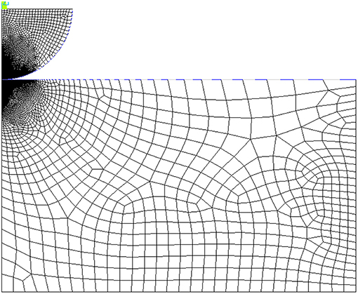
Figure 1. Finite element mesh for contact between a purely elastic sphere and a bilinear plastic flat.
The displacement (compressive load) was applied in 15 load steps that each contained 100 sub-steps, during which none of the elements experienced large deformations. The von Mises stress criterion was used to indicate the transition from elastic to elastic-plastic phase. The profiles of the flat's top surface were collected for 13 values of the tangential modulus and at 15 load steps (load steps were required for convergence). This data was used to describe the relation between the pile-ups and the strain hardening. The real contact radius, a, was determined in each case by finding the last surface node in contact with the sphere, taking its initial x-position, and subtracting the x-deformation at each sub-step. The sphere deformation ratio, (see Nomenclature), was calculated by collecting the sphere deformation, δs, at the contact tip and dividing it by the total displacement, Δ. The total reaction force, F, of the flat was measured by summing the individual reaction forces of each node in contact with the sphere. Finally, the normal average pressure, H, was calculated for each sub-step and for each Et.
In this work, unloading is not included in the modeling effort as the available models in the literature are both mature and applicable. The interested reader is referred to Ghaednia et al. (2015), Kogut and Komvopoulos (2004), and Wang et al. (2020) for more information regarding how the unloading phase behaves in a purely elastic manner. As a sample result, Figure 2 shows the von-Mises stress for Et = 0 (i.e., an elastic-perfectly plastic material) and Δ = 50 μm.
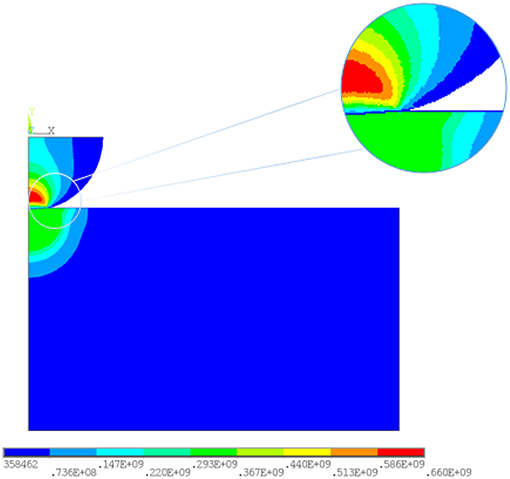
Figure 2. Von-Mises stress distribution for a contact between a purely elastic sphere and a bilinear elastic-plastic flat.
2.1. Finite Element Observations: Contact Parameters
Two sets of materials were modeled using FE to analyze the contact parameters. For both sets, the sphere is purely elastic with modulus of elasticity Es = 200 GPa and Poisson's ratio νs = 0.3. In set one, the flat is modeled as a bilinear material with modulus of elasticity Ef = 200 GPa, Poisson's ratio νf = 0.3 and yield strength Syf = 300 MPa, and for set two, the flat is modeled as a bilinear material with modulus of elasticity Ef = 71 GPa, Poisson's ratio νf = 0.29 and yield strength Syf = 200 MPa. Thirteen different tangential moduli (Et/Ef = 0, 0.01, 0.02, 0.03, 0.04, 0.06, 0.1, 0.2, 0.3, 0.4, 0.6, 0.9, and 1) have been used for each of the material sets. For each of the sets, four contact parameters were analyzed: deformations, real contact radius, contact force, and average normal pressure. For small loads approaching zero, the system behaves in a purely elastic manner. Thus, this regime approaches the results of Hertz's model (Hertz, 1882; Johnson, 1987). The numerical results shown in Figures 3–6 at the lowest load step are linearly connected to the Hertzian solution for displacements smaller than considered in the empirical model formulation.
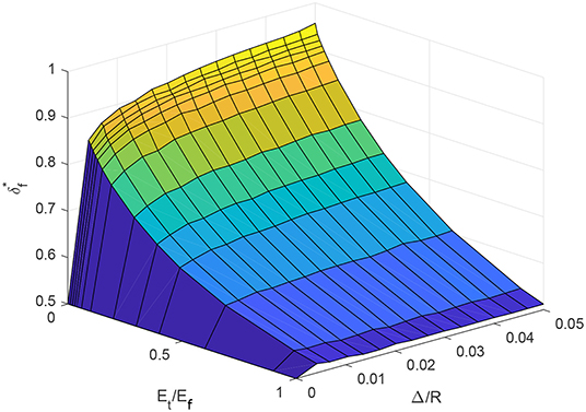
Figure 3. Variation of flat deformation ratio with respect to the strain hardening and applied displacement for material set 1 (numerical results).
Figure 3 shows the numerical results for deformation ratio of set one as a function of the tangential modulus Et/Ef and the applied displacement Δ/R. The deformation ratio here is defined as δf/Δ, where, δf and Δ are the deformation on the flat at the tip of the indenter and the applied displacement, respectively. At Δ/R = 0, Hertzian theory is applied on the results to create the boundary condition
For Δ/R < 0.01, the ratio exhibits a high sensitivity with respect to the deformation ratio Δ/R. As Δ/R approaches 0.02, transitions to being weakly dependent on the ratio of Δ/R and, in fact, is independent of Δ/R for Et/Ef > 0.1. With respect to the tangential modulus Et/Ef there is a continuous decrease in the deformation ratio value from the elastic-perfectly plastic material model (Et/Ef = 0) to purely elastic model (Et/Ef = 1). The results do not reach the Hertzian theory and shows around 2% larger values.
A similar trend was observed in Ghaednia et al. (2019), where the strain hardening effect on a flattening contact was studied, and the the same difference between the Hertzian theory and the FEM results was found. This result is likely due to neglecting the difference between indentation and flattening contact in Hertzian theory, where for both the cases the same effective radius of curvature is used.
The FEA results for the real contact radius is shown in Figure 4. The results show a large gradient with respect to the tangential modulus Et/Ef at the elastic-perfectly plastic limit (Et/Ef = 0) and converges to the purely elastic (Et/Ef = 1) solution at around Et/Ef = 0.2.
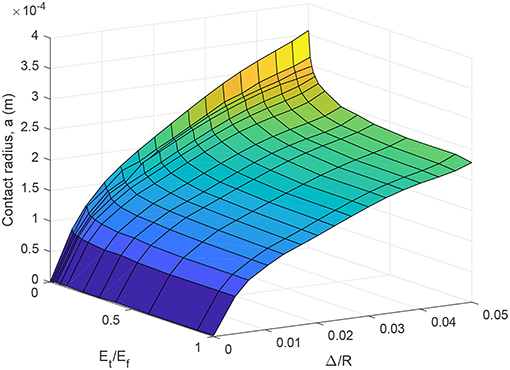
Figure 4. Variation of real contact radius with respect to strain hardening and applied displacement for material set 1 (numerical results).
The average normal pressure is shown in Figure 5. At the elastic-perfectly plastic limit (Et/Ef = 0) the results match the hardness values from the Jackson et al. (2015) model. For Et/Ef > 0, the average normal pressure should not be called hardness since the material never reaches the plastic flow regime. Therefore the term average normal pressure represents the physical meaning more precisely. Figure 5 shows a continuous increase from the elastic-perfectly plastic material model at Et/Ef = 0 to the purely elastic material model at Et/Ef = 1.
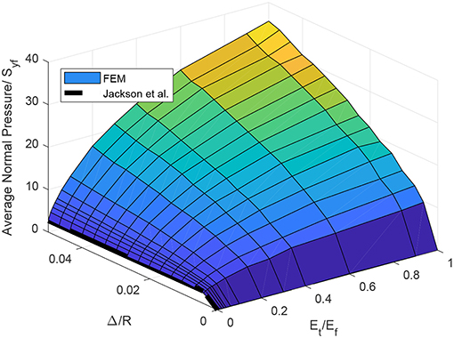
Figure 5. Changes in the normal average pressure with respect to the strain hardening and applied displacement for material set 1 (numerical results).
The variation of contact force with respect to deformations and strain hardening is depicted in Figure 6. The results show a continuous increase from the elastic-perfectly plastic material model (Et/Ef = 0) to the purely elastic material (Et/Ef = 1). The gradient with respect to Et/Ef is large at the elastic-perfectly plastic limit (Et/Ef = 0) and at large deformations, Δ/R. The Hertzian solution shows smaller values for Et/Ef = 1 that is likely due to the first order approximation of the contact radius, which fits a parabola onto on the sphere.
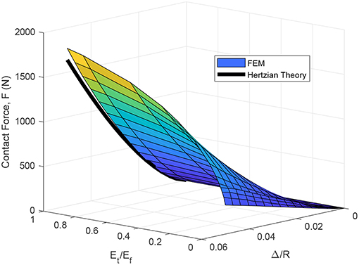
Figure 6. Variation of contact force with respect to the strain hardening and applied displacement for material set 1 (numerical results).
2.2. Finite Element Observations: Pile-Up vs. Sink-In
An Important characteristic of indentation is the proclivity of the material to exhibit pile-up, or sink-in. Figure 7A shows the results of the FEM simulations' contact profile on the flat for different tangential modulus Et/Ef values using the properties of material set one with 21 different tangential moduli from Et/Ef = 0 to 1. The position of the highest point at the profile of the flat top surface is used to measure the pile-up height. If the highest point is bellow the initial surface of the flat then the contact resulted in sink-in, and if this point is higher than the flat initial surface then the contact resulted into pile-up. It can be seen in Figure 7A that the pile-up happens for Et/Ef ≤ 6%. For Et/Ef > 6% the contact profile exhibits sink-in. At Et/Ef = 0 the profile shows an extremely sharp pile-up, as large as 30% of the indentation depth, that drops significantly to 3% of the indentation depth at Et/Ef = 0.01. The maximum indentation depth decreases from the elastic-perfectly plastic to the purely elastic material model. In Figure 7B, the volumetric ratio between the piled-up and sinked-in region
is shown, where, Vp and Vs are the pile-up and sink-in volumes, respectively, and y+ and y− are the domains at which y(x) ≥ 0 and y(x) < 0, respectively. The volumetric ratio exponentially decays from Et/Ef = 0 and converges to 0 at around 5%, which again shows the significant effect of strain hardening on pile-up at very small tangential moduli.
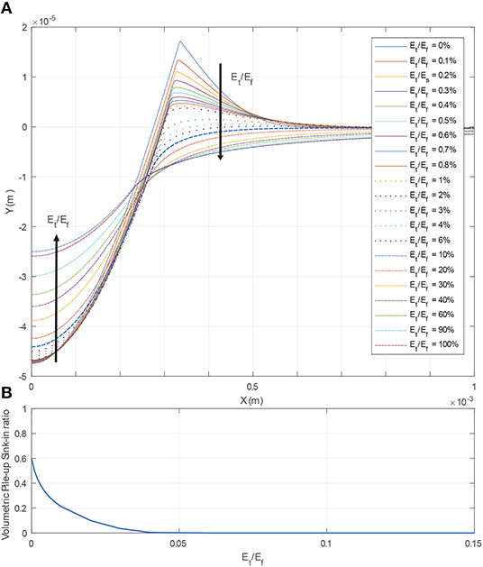
Figure 7. (A) Evolution of pile-up with respect to strain hardening. (B) Volumetric pile-up-sink-in ratio.
One of the parameters that can affect the pile-up/sink-in deformations is the elastic deformation on the indenter. Figure 8 shows the contact profile for six different sphere moduli Es = 10, 50, 100, 150, 200, and 250 GPa, and elastic-perfectly plastic flat, Et/Ef = 0, the rest of the material properties are the same as set one. It can be seen that the pile-up is directly related to the stiffness of the sphere; however, this does not transform the pile-ups into sink-in and the profile piles-up for all values of Es. There is a significant change from Es = 10 GPa to Es = 50 GPa, which is due to the flat not deforming as much as the sphere (recall, Ef = 200 GPa), as seen in Figure 8.
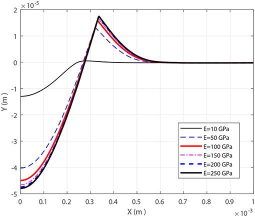
Figure 8. Effect of the indenter modulus of elasticity on surface profile for a elastic-perfectly plastic material.
Another important factor for the contact profile is the contact force or the total displacement of the indenter. In the FE model, (depending on whether the application is displacement controlled or force controlled) the load is applied as the penetration of the indenter to the flat. Figure 9 shows the contact profile for 15 load steps from Δ/R = 0.0042 to Δ/R = 0.05 for set 1 used in the initial observations. All of the load steps presented in Figure 9 are larger than the critical load needed to initiate yield in the flat. It can be seen that profile piles-up independent of the loading.
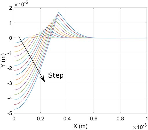
Figure 9. Effect of loading (in 15 steps) on surface profile for elastic-perfectly plastic material.
The contact parameters for set two show a similar trend as set one's. Thus, the graphs are not shown here; however, the data from set two have been used in the model development, presented in the next section.
3. Model Development
In the proposed formulation, the contact has been divided into two phases: elastic and elastic-plastic regimes. The contact starts with the elastic regime for very small deformations and continues to the elastic-plastic regime. Eventually the elastic-plastic regime converges to the fully plastic regime for large deformations.
3.1. Elastic Regime
The elastic regime follows the Hertzian theory. In this phase, the deformation on each object is calculated as
where E is the effective modulus of elasticity
In the Hertzian theory, the contact curvature is approximated with a polynomial and the contact radius is calculated up to the first order accuracy as
in terms of the equivalent radius, which is given as
The contact force for the elastic regime becomes
3.2. Elastic-Plastic Regime
For large deformations, plastic strains are present in the softer object (i.e., the object with the smaller yield strength). By definition, the elastic-plastic regime begins at the initiation of yield, which occures at some point beneath the contact surface. Following Johnson (1987), this critical point is calculated using the von Mises stress criterion, which gives the critical deformation for the onset of yield as:
where the material properties of the flat (as the more compliant material) are used, and Λ(ν) is solved from Johnson (1987):
Jackson and Green (2005) proposed an approximation for the solution of Eq. (10):
such that from Jackson and Green (2005) C is a fit to the numerical solution of Eq. (10)
Therefore, the elastic-plastic phase starts and continues for deformations Δ > Δc.
To develop a predictive formulation for the elastic-plastic regime, several governing conditions have been applied to the model development to ensure that continuity, boundary conditions, continuity of the first derivatives, and the physical meaning are preserved in the formulation. In the following, the model development for the flat's deformation ratio, , the real contact radius, a, and contact force, F are discussed. The formulations focus on two of the main effects that are neglected in almost all previous models: first, the effect of the bilinear strain hardening from elastic-perfectly plastic Et = 0 to fully elastic Et = Ef, and second, the elastic deformations on the indenter during contact.
3.2.1. Deformation
The deformation ratio of the flat is defined as
Several assumption governing the form of this ratio are made. First, it is explicitly a function of the ratio of the elastic moduli Et/Ef and the non-dimensionalized deformation Δ/R. Second, it must satisfy a set of governing conditions that are defined in what follows. Other variables, such as the effective modulus of elasticity and Poisson ratio, are implicitly incorporated into the elastic limit and the large deformation limit, defined below. Under these assumptions, the functional form of the deformation ratio, in the most general case, is expressed as
Here, both ratios (Δ/R and Et/Ef) only exist on the intervals of [0,1]. The deformation ratio (Equation 14) must also satisfy the governing conditions (GCs) that are based on the results shown in Figures 3–6:
For small deformation ratios, the elastic solution must be recovered
(I)
Likewise, for a purely elastic material, the elastic solution must hold for all deformations
(II)
In GCs (I,II), is defined as the elastic limit of the deformation ratio, which is calculated via Equation (4).
For the large deformation limit, since the flat is assumed to have a bilinear material model, the solution for large deformations is assumed to be the same as an elastic material with the same elastic modulus as the system (Et = Ef)
(III)
Here, is defined as the deformation ratio at the large deformation limit, which can be estimated as
Equation (15) is defined in terms of , which is the reduced modulus of elasticity for a purely elastic flat having modulus Ef = Et. This simplification is verified against the finite element results, and is shown for material sets one and two in Figure 10. In this comparison, the FEM results are shown for an applied displacement of Δ/R = 0.05, which is well below the maximum displacement ratio considered of Δ/R = 1. It is observed from this comparison that the deformation ratio quickly converges to the large deformation limit, which justifies the assumption implicit in GC (III). At Et = Ef, even though FEM results are expected to reach the Hertzian solution, Figure 10 shows 2% smaller values compared to Hertzian theory. The reason is most likely the definition of the equivalent radius of curvature in the Hertzian theory, which does not consider any difference between the flat and the sphere. Since this difference is not significant, the upper limit, Ef = Et, is left to be the Hertzian theory. This difference has been considered in the final formulation to decrease the errors in the predictions.
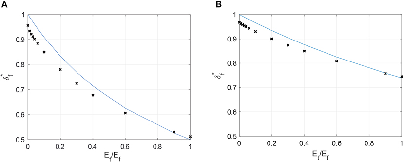
Figure 10. Comparison of the FEA results (x) and the assumption of GC III at the large deformation limit (Δ/R = 0.05). (A) Material set 1. (B) Material set 2.
For large deformations, asymptotically converges to the large deformation limit. This is modeled by assuming that the gradient of with respect to the applied displacement is 0 for large Δ/R.
(IV)
From Figure 10, no convergence for with respect to Et/Ef can be seen, which can be expressed mathematically in GC (V) as
(V)
The final two GCs define constraint conditions for the derivatives of the deformation ratio along the boundaries (with respect to both Δ/R and Et/Ef):
(VI)
(VII)
A seperation of variables solution is proposed for f via
From GC (I) and (II), it is apperant that neither ψ not ϕ are constants. Further, in applying these constraints to the functional form of Equation (16), the constraints of GCs (I) and (II) can be rewritten in terms of ϕ and ψ as:
Substitution of these two constraints on ϕ and ψ into GC (III) yields a new constraint equation on the product of ϕ, ψ at one of the boundaries:
As ψ is not constant, the application of GC (IV) to the functional form of Equation (16) establishes that
which yields
A final set of constraints on ϕ and ψ come from GCs (V) and (VI):
To satisfy the constraints established in the GCs and detailed through Equations (16) to (23), the functional form
is proposed, where the coefficients, βi and λi have been calculated from fitting to FEM results for sets one and two, with Et/Es = 0, 0.01, 0.02, 0.03, 0.04, 0.06, 0.1, 0.2, 0.3, 0.4, 0.6, 0.9, 1 and for 40 increments of Δ/R from Δ/R = 0 to Δ/R = 0.05. Note that Equation (25) automatically satisfies GC (VII).
3.2.2. Real Contact Radius
Using the model of Equation 25 and the FEA results presented in Section 2, it is proposed that the real contact radius during elastic-plastic contact follows the form of
where is the Hertzian contact radius and χ is
with χ found from fitting to the FEM results (with mean absolute error less than 2%) and and can be found from Hertzian theory and Equation (25), respectively. The elastic-perfectly plastic, Et = 0, limit of Equation (25) reduces to
The elastic-perfectly plastic limit, aep, at large deformations is the real contact radius that is used in the majority of the hardness measurements using spherical indenters, such as nano and micro indentation tests. Even though the effect of pile-up is not directly mentioned in development of the contact radius formulation, the effect of pile-up and sink-in is considered as the effect of strain hardening and is thus embedded in the equations.
3.2.3. Contact Force
To formulate the contact force, the average normal pressure at very large deformations, conventionally called Hardness, is assumed to increase linearly from hardness for elastic-perfectly plastic materials to average normal pressure from Hertzian theory
where is the average normal pressure is Hertzian theory and is calculated as
and H is the hardness calculated from the analytical solution by Jackson et al. (2015) for elastic-perfectly plastic materials as:
Equation (28) presents a linear transition from elastic-perfectly plastic to purely elastic materials with respect to the tangent modulus. The limit of the contact force at large deformations is proposed as:
The coefficients γj, j = 1, 2, 3, are fitted to the FEM results. The elastic-plastic contact force is thus calculated via:
where Fe and FLD are from the Hertzian theory (Johnson, 1987) and Equation (31), respectively, and We and WLD are fitted to FEM results as
and the coefficients αj, j = 1, 2, 3, 4, are fitted to the FEM results with absolute mean error less than 2%.
4. Results and Discussion
4.1. Model Verification
To verify the predictions of the new model, the new formulation is compared with the contact of six different material combinations with properties listed in Table 1. Here, Mat1 to Mat6 are indentation contacts of:
Mat1 Aluminum (Al) 6061 flat and Stainless Steel (SS) 304 indenter,
Mat2 Al 5005 flat and Alloy Steel (AS) 4130 indenter,
Mat3 Carbon Steel (CS) 1070 flat and Tungsten Carbide (WC) indenter,
Mat4 AS 4130 flat and WC Indenter,
Mat5 SS 304 flat and WC indenter,
Mat6 Titanium-G1 flat and SS 304 indenter.
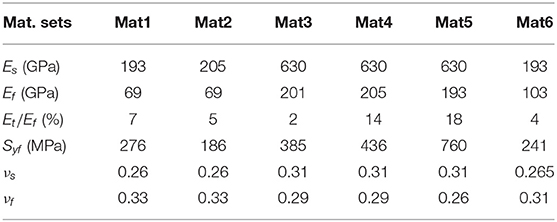
Table 1. Material sets used in the comparisons.
These material sets (in particular, sets 3, 4, and 5) were chosen to validate the model outside of the material range that was used for model development. For each of the comparison sets, three parameters are studied: the deformation ratio, real contact radius, and contact force. Unfortunately, comparison with previous models (such as Ye and Komvopoulos, 2003; Jackson and Green, 2005; Ghaednia et al., 2016; Wang et al., 2020) was not possible because those models do not consider the effect of strain hardening. Thus, comparison between them and the present model would be dominated by the significant differences in material models and would be unfair.
As an exmaple of using the presented equations, the contact parameters for Mat1 has been calculated. A Matlab script was written to calculate the deformations, contact area, and contact force for different applied displacements. In each iteration of the loop, the critical deformation from Equation (11) is first calculated. The deformation was then determined to be either in the elastic regime (if Δ ≤ Δc), in which case Equations (4–8) would be employed, or in the plastic regime (Δ > Δc). For deformations within the plastic regime, the deformation ratio, , was calculated from Equations (13–25), contact radius from Equation (25), and for the contact force Equation (32) is used.
Figure 11 shows the comparison for Mat1, the contact of Al 6061 flat and a SS 304 sphere with R = 1 mm. It can be seen that for the deformation ratio, the predictions match the FE results very well with mean absolute error less than and maximum error, . For the real contact radius, the model shows a very good match with maximum error ema = 2.6% and mean absolute error ea = 0.8%. The predictions for the contact force also shows a reasonable match with maximum and mean absolute error emF = 5.9% and eF = 4.7%, respectively.
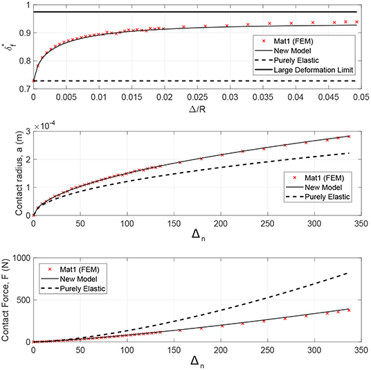
Figure 11. Mat 1 comparisons between FEM results, new formulation and Hertzian theory for deformation ratio, contact area and contact force.
The same quantities are compared for each of the other five material combinations, and are summarized in Table 2, which shows the mean absolute error values for all of the cases, where Δm/δc shows the maximum normalized deformation applied on each of the material combinations. All of the maximum normalized deformations that have been analyzed are well over 110, which is the limit for fully plastic flow in Kogut and Etsion (2002). Thus, the analysis shows the transition from purely elastic to elastic-plastic to purely plastic regimes. The deformation ratio results show a maximum mean absolute error of 0.7% among all of the compared materials. The maximum error for the deformation ratio is 2.4%. The contact radius shows the maximum mean absolute error 1.6% with maximum error being 6.7%. For the contact force the maximum mean absolute error and maximum error are 5.6 and 8.3%, respectively.
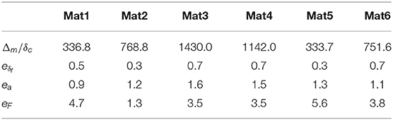
Table 2. Maximum normalized deformation and mean absolute errors.
Figure 12 shows the loglog comparison of real contact radius vs. normalized deformation between the FEM results and formulation predictions for all of he six material properties shown in Table 1. For each set, the closest line to the FEM results is the prediction for that material set. Material sets Mat3 and Mat4 have the smallest contact radii as functions of deformation; Mat3 represents a highly plastic case with modulus Ef/Syf = 522 and very small strain hardening Et/Ef = 0.02, and Mat4 represents a highly plastic contact with Ef/Syf = 470 and large tangential modulus Et/Ef = 0.14. Mat1 and Mat5 both show the largest contact radii for a given displacement, and they represent more compliant materials compared to Mat3 and Mat4.
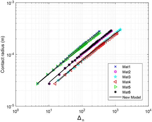
Figure 12. Comparison between all materials for real contact radius in loglog scale. The markers show the results from the FE simulations, and the continuous lines show the predictions.
Figure 13 shows the comparison of contact force with respect to the normalized deformation between the FE simulations and the predictions for material properties presented in Table 1. Overall, the predictions show a very good match with the differences presented in Table 2.
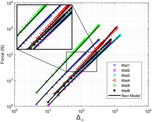
Figure 13. Comparison between all materials for contact force in loglog scale. The markers show the FEM results and the continuous lines show the predictions.
4.2. Comparison With Experimental Data
As a final comparison, the experimental data recorded by Brake et al. (2017) was used to validate the proposed model against experimental data. Additionally, the Jackson-Green (Jackson and Green, 2005), Ye-Komvopoulos (Ye and Komvopoulos, 2003), and Kogut-Etsion (Kogut and Etsion, 2002) models are compared to the experimental data too as the available data in the literature is similar to elastic-perfectly plastic contact (i.e., the experimental data available in the literature for the indentation contact of metallic materials does not adequately span the strain hardening regime for validating the new model). In Brake et al. (2017), amongst other experiments, the indentation contact of common aerospace materials by a sapphire sphere for peak loads of 25 mN, 100, mN, 5 N, and 10 N was analyzed. From Brake et al. (2017) the data for indentation of Aluminum 6160 (Al 6160) and Stainless Steel 304 (SS 304) with peak load of 10 N is used here. The material properties reported in Brake et al. (2017) for these experiments are summarized in Table 3. Both of the materials are considered to be elastic-perfectly plastic.
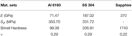
Table 3. Material properties used from Brake et al. (2017).
Figure 14 shows the comparison between the new model, the previous models, and the data from Brake et al. (2017). The results show relatively small elastic-plastic deformations with normalized deformations up to δn≃6. This is due to the applied force of 10 N during the experiments. Therefore, the contact has just entered the elastic-plastic regime. Hertzian (elastic) contact is also shown on the graph as a baseline for comparison. The new model, Kogut-Etsion Kogut and Etsion (2002), and Jackson-Green (Jackson and Green, 2005) models are all acceptable compared to the experimental data. The previous flattening model (Ghaednia et al., 2019) and the Jackson-Green model (Jackson and Green, 2005) are coincident for the case of elastic-perfectly plastic materials, as modeled here, and is thus not shown. One interesting observation is that from 1 < Δn < 4 experimental data shows larger results than Hertzian theory, which is considered the upper limit of the contact.
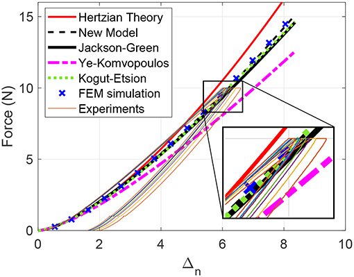
Figure 14. Comparison between the new model and experimental data from Brake et al. (2017) for Al 6160.
In Figure 15, the same comparison as in Figure 14 is shown between the experimental data (Brake et al., 2017), the proposed model, and the previous models. The experimental results show normalized deformation of up to δn = 17, which is still in the lower ranges of elastic-plastic regime. The new model compares better with the experimental data than the other models; however, at larger deformations (Δn > 15) the experiments show a slight decrease in the slope and a negative second derivation.
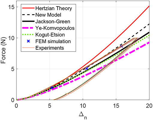
Figure 15. Comparison between the new model and experimental data from Brake et al. (2017) for Stainless Steel 304.
4.3. Influence on Frictional Sliding
Together with Ghaednia et al. (2019), four different conditions of contact can be considered:
1. Rigid on rigid,
2. Flattening (an elastic-plastic sphere against an elastic or rigid substrate),
3. Indentation (pile-up; an elastic sphere against an elastic-perfectly plastic flat),
4. Indentation (sink-in; an elastic sphere against a strain hardening flat).
The condition of rigid on rigid could be more broadly contextualized as elastic on elastic for small deformations; once the deformations become large, the contact evolves into one of the other three conditions. Additionally, flattening could also include large deformations of an elastic sphere against a rigid (or very stiff) substrate. For these four different conditions of contact, the surface deformations are substantially different, as shown in Figure 16. Once tangential loads are applied to these four different conditions of contact, significantly different frictional forces are to be expected. Given a coefficient of friction of μ = 0.6, the frictional force defined for rigid on rigid contact is ff = μN for a given normal load N. From preliminary simulations of tangential loads applied after normal loads to a flattening case (Al 6061 sphere, WC flat), a pile-up case (WC sphere, Al 6061 flat with Et/Ef = 0), and a sink-in case (WC sphere, Al 6061 flat with Et/Ef = 1), the frictional behavior is summarized in Table 4. For all cases, the material properties of Table 1 are used unless otherwise noted; a normal displacement of 0.05 mm is first applied, then tangential displacements of 0.1 mm are applied across 100 load steps. Coulomb friction is modeled with μ = 0.6 for all cases. As is evidenced by the table, the contact condition can result in effective coefficients of friction that are up to 50% greater than the rigid on rigid case. These effective μ are, of course, dependent on a number of parameters: normal indentation, tangential displacement, and bilinear stiffness amongst others. As these parameters are varied, the pile-up contact condition is found to have an effective μ close to 1, while the flattening and skin-in conditions can exhibit effective μ close to 0.5. This makes sense as significantly more material is displaced by tangential motion in the pile-up case than in the sink-in or flattening cases. It is therefore clear that the conditions of flattening, pile-up, and sink in must be treated differently and that the historical approach of using one contact model to describe all three cases is insufficient. As these results are preliminary, they merit further investigation in subsequent work.
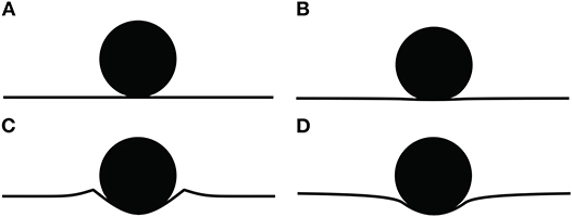
Figure 16. Surface profiles for (A) rigid on rigid contact, (B) flattening contact, (C) pile-up contact, and (D) indentation contact.
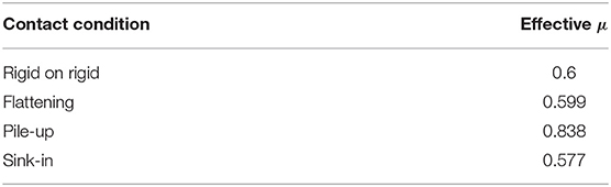
Table 4. Effective coefficients of friction for different tangential displacements.
5. Conclusion
In this work, a new formulation for a frictionless elastic-plastic single asperity indentation contact of a sphere and a flat has been presented. The work focuses on two aspects of elastic-plastic contact, the effect of bilinear strain hardening and the elastic deformations on the indenter. The presented formulations considers the bilinear strain hardening from elastic-perfectly plastic to perfectly elastic contact.
The formulation presented in this work provides an empirical fit to the FEM results for a wide range of engineering metals. Deformations on both of the objects, real contact radius, and contact force have been considered in the model. Several different governing conditions have been applied on the formulation to ensure that the continuity, boundary conditions, and common physics limits are satisfied. The formulation was compared with FE simulations for six different material combinations, and the accuracy of the predictions was verified.
In addition to the contact parameters, the occurrence of pile-up and sink-in on the contact surface have been analyzed. For elastic-perfectly plastic materials the contact surface shows very large pile-ups. Further, pile-up transforms to sink-in rapidly with respect to the strain hardening. From Et/Ef = 0 to Et = Ef = 0.01 the maximum peak height of the surface profile decreases by an order of magnitude, and at Et/Ef = 0.06, the pile-up has been completely transformed into sink-in. Moreover, the dependency of the pile-up on the elastic deformations of the indenter and the loading has been analyzed. It was shown that the strain hardening has the dominant effect compared to the loading and indenter's elastic deformations.
In this work the indenter was considered to be perfectly elastic. Due to the strain hardening of the flat, for very large deformations, the contact stresses reach very large states that, in reality, would cause the indenter to yield; however, it must be considered that for a high strength indenter, the flat will fail before the indenter yields. This scenario becomes problematic when the yield strength of the contact materials are close, in which case both of the objects reach the elastic-plastic regime at similar deformations. This phenomena is not within the scope of the present study, and is relegated to the future work.
Finally it has been shown in this work that even 1% tangential modulus significantly affects the contact parameters. A new predictive formulation based on an empirical formulation of the FEM results has been provided for deformations on the objects, contact radius, and contact force. The current work, along with previous work on the effect of strain hardening in flattening contact (Ghaednia et al., 2019) are providing a comprehensive predictive formulation for a majority of engineering applications. There is significant work to be done for a better understanding of single asperity contact. One of the areas that is lacking in the literature is lack of experimental data for pile-up during the loading phase. The challenge is that the measurements need to be conducted during compression of the flat. During the unloading phase, the pile-ups change significantly. There are two main parameters that should be considered in future studies: the effect of friction on pile-up and sink-in, and the effect of strain hardening on both of the objects in contact.
Data Availability Statement
The raw data supporting the conclusions of this article will be made available by the authors, without undue reservation.
Author Contributions
HG designed the project, conducted the analytical modeling, oversaw all of the work, and wrote the paper. GM and PL conducted all of the normal indentation FEA modeling. EO'N conducted the frictional FEA modeling. MB oversaw the project and edited and revised the paper.
Funding
This research was partially supported by a grant from the Taiho Kogyo Tribology Research Foundation.
Conflict of Interest
The authors declare that the research was conducted in the absence of any commercial or financial relationships that could be construed as a potential conflict of interest.
References
Adams, G., and Nosonovsky, M. (2000). Contact modelling-forces. Tribol. Int. 33, 431–442. doi: 10.1016/S0301-679X(00)00063-3
Barber, J., and Ciavarella, M. (2000). Contact mechanics. Int. J. Solids Struct. 37, 29–43. doi: 10.1016/S0020-7683(99)00075-X
Bhushan, B. (1996). Contact mechanics of rough surfaces in tribology: single asperity contact. Appl. Mech. Rev. 49, 275–298. doi: 10.1115/1.3101928
Bhushan, B. (1998). Contact mechanics of rough surfaces in tribology: multiple asperity contact. Tribol. Lett. 4, 1–35.
Biwa, S., and Storåkers, B. (1995). An analysis of fully plastic Brinell indentation. J. Mech. Phys. Solids 43, 1303–1333. doi: 10.1016/0022-5096(95)00031-D
Borjali, A., Langhorn, J., Monson, K., and Raeymaekers, B. (2017). Using a patterned microtexture to reduce polyethylene wear in metal-on-polyethylene prosthetic bearing couples. Wear 392, 77–83. doi: 10.1016/j.wear.2017.09.014
Borjali, A., Monson, K., and Raeymaekers, B. (2018). Friction between a polyethylene pin and a microtextured cocrmo disc, and its correlation to polyethylene wear, as a function of sliding velocity and contact pressure, in the context of metal-on-polyethylene prosthetic hip implants. Tribol. Int. 127, 568–574. doi: 10.1016/j.triboint.2018.07.005
Borjali, A., Monson, K., and Raeymaekers, B. (2019). Predicting the polyethylene wear rate in pin-on-disc experiments in the context of prosthetic hip implants: deriving a data-driven model using machine learning methods. Tribol. Int. 133, 101–110. doi: 10.1016/j.triboint.2019.01.014
Brake, M. (2012). An analytical elastic-perfectly plastic contact model. Int. J. Solids Struct. 49, 3129–3141. doi: 10.1016/j.ijsolstr.2012.06.013
Brake, M. (2015). An analytical elastic plastic contact model with strain hardening and frictional effects for normal and oblique impacts. Int. J. Solids Struct. 62, 104–123. doi: 10.1016/j.ijsolstr.2015.02.018
Brake, M., Reu, P. L., and Aragon, D. S. (2017). A comprehensive set of impact data for common aerospace metals. J. Comput. Nonlinear Dyn. 12:061011. doi: 10.1115/1.4036760
Brizmer, V., Zait, Y., Kligerman, Y., and Etsion, I. (2006). The effect of contact conditions and material properties on elastic-plastic spherical contact. J. Mech. Mater. Struct. 1, 865–879. doi: 10.2140/jomms.2006.1.865
Chang, W., Etsion, I., and Bogy, D. B. (1987). An elastic-plastic model for the contact of rough surfaces. J. Tribol. 109, 257–263. doi: 10.1115/1.3261348
Chang, W.-R. (1986). Contact, Adhesion, and Static Friction of Metallic Rough Surfaces. Berkeley, CA: University of California.
Christoforou, A. P., Yigit, A. S., and Majeed, M. (2013). Low-velocity impact response of structures with local plastic deformation: characterization and scaling. J. Comput. Nonlinear Dyn. 8:011012. doi: 10.1115/1.4006532
Firrone, C. M., and Zucca, S. (2011). Modelling friction contacts in structural dynamics and its application to turbine bladed disks. Numer. Anal. Theor. Appl. 14, 301–334. doi: 10.5772/25128
Flicek, R. C. (2015). Analysis of complete contacts subject to fatigue (Ph.D. thesis). Oxford University, Oxford, United Kingdom.
Follansbee, P., and Sinclair, G. (1984). Quasi-static normal indentation of an elasto-plastic half-space by a rigid sphere-I: analysis. Int. J. Solids Struct. 20, 81–91. doi: 10.1016/0020-7683(84)90078-7
Ghaednia, H., Brake, M. R., Berryhill, M., and Jackson, R. L. (2019). Strain hardening from elastic-perfectly plastic to perfectly elastic flattening single asperity contact. J. Tribol. 141:031402. doi: 10.1115/1.4041537
Ghaednia, H., Jackson, R. L., and Gao, J. (2014). “A third body contact model for particle contaminated electrical contacts,” in 2014 IEEE 60th Holm Conference on Electrical Contacts (Holm) (New Orleans, LA: IEEE), 1–5. doi: 10.1109/HOLM.2014.7031018
Ghaednia, H., and Marghitu, D. B. (2016). Permanent deformation during the oblique impact with friction. Arch. Appl. Mech. 86, 121–134. doi: 10.1007/s00419-015-1108-2
Ghaednia, H., Marghitu, D. B., and Jackson, R. L. (2015). Predicting the permanent deformation after the impact of a rod with a flat surface. J. Tribol. 137:011403. doi: 10.1115/1.4028709
Ghaednia, H., Pope, S. A., Jackson, R. L., and Marghitu, D. B. (2016). A comprehensive study of the elasto-plastic contact of a sphere and a flat. Tribol. Int. 93, 78–90. doi: 10.1016/j.triboint.2015.09.005
Ghaednia, H., Wang, X., Saha, S., Xu, Y., Sharma, A., and Jackson, R. L. (2017). A review of elastic-plastic contact mechanics. Appl. Mech. Rev. 69:060804. doi: 10.1115/1.4038187
Gheadnia, H., Cermik, O., and Marghitu, D. B. (2015). Experimental and theoretical analysis of the elasto-plastic oblique impact of a rod with a flat. Int. J. Impact Eng. 86, 307–317. doi: 10.1016/j.ijimpeng.2015.08.007
Golgoon, A., Sadik, S., and Yavari, A. (2016). Circumferentially-symmetric finite eigenstrains in incompressible isotropic nonlinear elastic wedges. Int. J. Nonlinear Mech. 84, 116–129. doi: 10.1016/j.ijnonlinmec.2016.04.007
Golgoon, A., and Yavari, A. (2017). On the stress field of a nonlinear elastic solid torus with a toroidal inclusion. J. Elastic. 128, 115–145. doi: 10.1007/s10659-016-9620-3
Golgoon, A., and Yavari, A. (2018). Nonlinear elastic inclusions in anisotropic solids. J. Elastic. 130, 239–269. doi: 10.1007/s10659-017-9639-0
Green, I. (2005). Poisson ratio effects and critical values in spherical and cylindrical Hertzian contacts. Appl. Mech. Eng. 10:451.
Green, I., and Etsion, I. (1985). Stability threshold and steady-state response of noncontacting coned-face seals. ASLE Trans. 28, 449–460. doi: 10.1080/05698198508981642
Hardy, C., Baronet, C., and Tordion, G. (1971). The elasto-plastic indentation of a half-space by a rigid sphere. Int. J. Num. Methods Eng. 3, 451–462. doi: 10.1002/nme.1620030402
Hertz, H. (1882). Über die berührung fester elastischer körper. Journal f ur die reine und angewandte Mathematik¨ 92, 156–171. doi: 10.1515/crll.1882.92.156
Ishlinsky, A. (1944). The problem of plasticity with axial symmetry and Brinell's test. J. Appl. Math. Mech. 8, 201–224.
Jackson, R. L., Ghaednia, H., Elkady, Y. A., Bhavnani, S. H., and Knight, R. W. (2012). A closed-form multiscale thermal contact resistance model. IEEE Trans. Components Packaging Manufact. Technol. 2, 1158–1171. doi: 10.1109/TCPMT.2012.2193584
Jackson, R. L., Ghaednia, H., and Pope, S. (2015). A solution of rigid-perfectly plastic deep spherical indentation based on slip-line theory. Tribol. Lett. 58:47. doi: 10.1007/s11249-015-0524-3
Jackson, R. L., and Green, I. (2003). “A finite element study of elasto-plastic hemispherical contact,” in Proceeding of 2003 STLE/ASME Joint Tribology Conference (Ponte Vedra Beach, FL). doi: 10.1115/2003-TRIB-0268
Jackson, R. L., and Green, I. (2005). A finite element study of elasto-plastic hemispherical contact against a rigid flat. Trans. ASME F J. Tribol. 127, 343–354. doi: 10.1115/1.1866166
Jackson, R. L., and Kogut, L. (2006). A comparison of flattening and indentation approaches for contact mechanics modeling of single asperity contacts. J. Tribol. 128, 209–212. doi: 10.1115/1.2114948
Kardel, K., Ghaednia, H., Carrano, A. L., and Marghitu, D. B. (2017). Experimental and theoretical modeling of behavior of 3d-printed polymers under collision with a rigid rod. Addit. Manufact. 14, 87–94. doi: 10.1016/j.addma.2017.01.004
Kogut, L., and Etsion, I. (2002). Elastic-plastic contact analysis of a sphere and a rigid flat. J. Appl. Mech. 69, 657–662. doi: 10.1115/1.1490373
Kogut, L., and Komvopoulos, K. (2004). Analysis of the spherical indentation cycle for elastic-perfectly plastic solids. J. Mater. Res. 19, 3641–3653. doi: 10.1557/JMR.2004.0468
Komvopoulos, K. (1989). Elastic-plastic finite element analysis of indented layered media. ASME J. Tribol. 111, 430–439. doi: 10.1115/1.3261943
Langhorn, J., Borjali, A., Hippensteel, E., Nelson, W., and Raeymaekers, B. (2018). Microtextured cocrmo alloy for use in metal-on-polyethylene prosthetic joint bearings: multi-directional wear and corrosion measurements. Tribol. Int. 124, 178–183. doi: 10.1016/j.triboint.2018.04.007
Lin, L. P., and Lin, J. F. (2006). A new method for elastic-plastic contact analysis of a deformable sphere and a rigid flat. J. Tribol. 128, 221–229. doi: 10.1115/1.2164469
Mesarovic, S. D., and Fleck, N. A. (2000). Frictionless indentation of dissimilar elastic-plastic spheres. Int. J. Solids Struct. 37, 7071–7091. doi: 10.1016/S0020-7683(99)00328-5
Miller, B. A., and Green, I. (2001). Numerical formulation for the dynamic analysis of spiral-grooved gas face seals. J. Tribol. 123, 395–403. doi: 10.1115/1.1308015
Mollaeian, K., Liu, Y., Bi, S., and Ren, J. (2018). Atomic force microscopy study revealed velocity-dependence and nonlinearity of nanoscale poroelasticity of eukaryotic cells. J. Mech. Behav. Biomed. Mater. 78, 65–73. doi: 10.1016/j.jmbbm.2017.11.001
Pawlowski, A. E., Cordero, Z. C., French, M. R., Muth, T. R., Carver, J. K., Dinwiddie, R. B., et al. (2017). Damage-tolerant metallic composites via melt infiltration of additively manufactured preforms. Mater. Design 127, 346–351. doi: 10.1016/j.matdes.2017.04.072
Rathbone, D., Marigo, M., Dini, D., and van Wachem, B. (2015). An accurate force-displacement law for the modelling of elastic-plastic contacts in discrete element simulations. Powder Technol. 282, 2–9. doi: 10.1016/j.powtec.2014.12.055
Sadeghi, F., Jalalahmadi, B., Slack, T. S., Raje, N., and Arakere, N. K. (2009). A review of rolling contact fatigue. J. Tribol. 131:041403. doi: 10.1115/1.3209132
Shankar, S., and Mayuram, M. (2008). A finite element based study on the elastic-plastic transition behavior in a hemisphere in contact with a rigid flat. J. Tribol. 130:044502. doi: 10.1115/1.2958081
Sharma, A., and Jackson, R. L. (2017). A finite element study of an elasto-plastic disk or cylindrical contact against a rigid flat in plane stress with bilinear hardening. Tribol. Lett. 65:112. doi: 10.1007/s11249-017-0894-9
Sinclair, G., Follansbee, P., and Johnson, K. (1985). Quasi-static normal indentation of an elasto-plastic half-space by a rigid sphere-II. results. Int. J. Solids Struct. 21, 865–888. doi: 10.1016/0020-7683(85)90039-3
Wang, H., Yin, X., Hao, H., Chen, W., and Yu, B. (2020). The correlation of theoretical contact models for normal elastic-plastic impacts. Int. J. Solids Struct. 182, 15–33. doi: 10.1016/j.ijsolstr.2019.07.018
Ye, N., and Komvopoulos, K. (2003). Indentation analysis of elastic-plastic homogeneous and layered media: Criteria for determining the real material hardness. J. Tribol. 125, 685–691. doi: 10.1115/1.1572515
Zhao, B., Zhang, S., Wang, Q., Zhang, Q., and Wang, P. (2015). Loading and unloading of a power-law hardening spherical contact under stick contact condition. Int. J. Mech. Sci. 94, 20–26. doi: 10.1016/j.ijmecsci.2015.02.013
Zhao, D., Banks, S. A., Mitchell, K. H., D'Lima, D. D., Colwell, C. W., and Fregly, B. J. (2007). Correlation between the knee adduction torque and medial contact force for a variety of gait patterns. J. Orthopaed. Res. 25, 789–797. doi: 10.1002/jor.20379
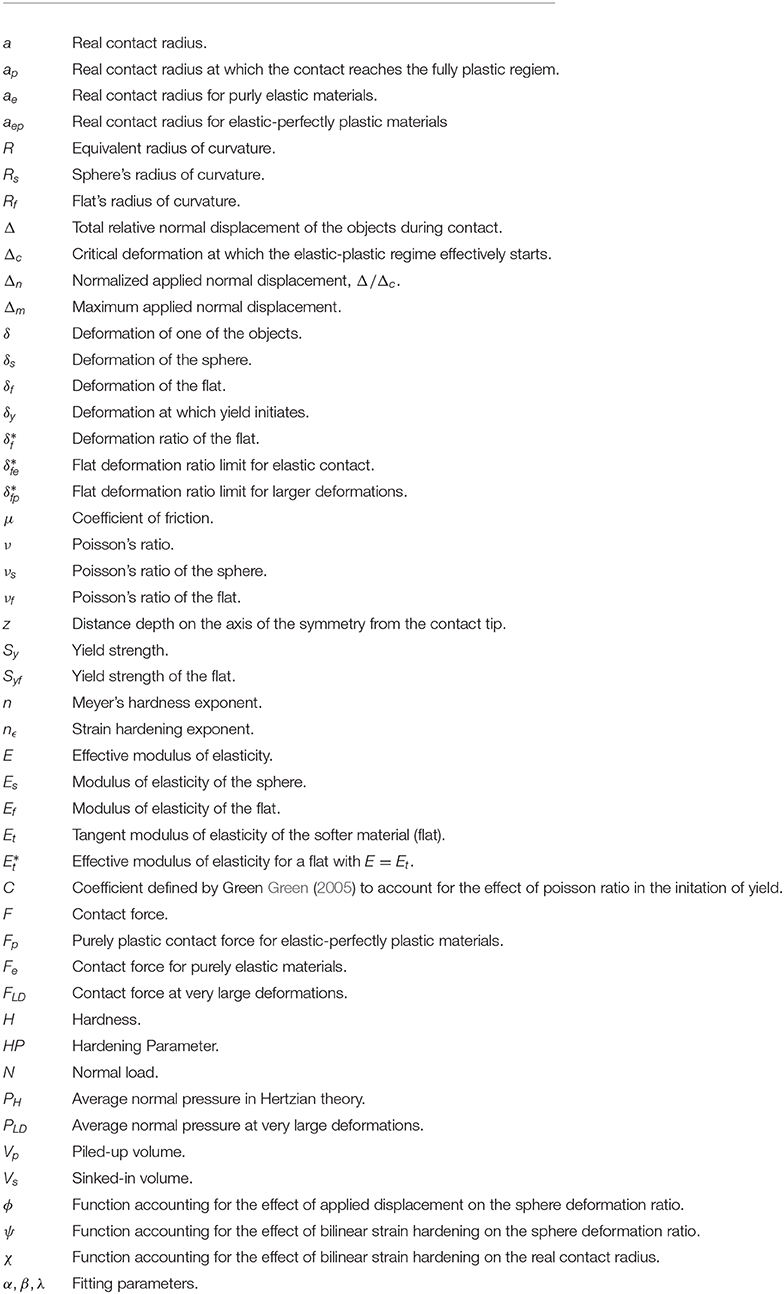
6. Nomenclature
Keywords: bilinear strain hardening, elastic plastic contact, indentation, constitutive modeling, pile-up and sink-in
Citation: Ghaednia H, Mifflin G, Lunia P, O'Neill EO and Brake MRW (2020) Strain Hardening From Elastic-Perfectly Plastic to Perfectly Elastic Indentation Single Asperity Contact. Front. Mech. Eng. 6:60. doi: 10.3389/fmech.2020.00060
Received: 21 March 2020; Accepted: 26 June 2020;
Published: 05 August 2020.
Edited by:
Elena Torskaya, Institute for Problems in Mechanics (RAS), RussiaReviewed by:
J. Jamari, Diponegoro University, IndonesiaSergei Mikhailovich Aizikovich, Don State Technical University, Russia
Copyright © 2020 Ghaednia, Mifflin, Lunia, O'Neill and Brake. This is an open-access article distributed under the terms of the Creative Commons Attribution License (CC BY). The use, distribution or reproduction in other forums is permitted, provided the original author(s) and the copyright owner(s) are credited and that the original publication in this journal is cited, in accordance with accepted academic practice. No use, distribution or reproduction is permitted which does not comply with these terms.
*Correspondence: Matthew R. W. Brake, YnJha2VAcmljZS5lZHU=