 Jun Ji
 Dongting Li
 Yong Li
 Yun Jing1,3*
- 1Graduate Program in Acoustics, The Pennsylvania State University, University Park, PA, United States
- 2Institute of Acoustics, School of Physics Science and Engineering, Tongji University, Shanghai, China
- 3Department of Mechanical and Aerospace Engineering, North Carolina State University, Raleigh, NC, United States
A broadband sound absorption attained by a deep-subwavelength structure is of great interest to the noise control community especially for extremely low frequencies (20–100 Hz) in room acoustics. Coupling multiple different resonant unit cells has been an effective strategy to achieve a broadband sound absorption. In this paper, we report on an analytical, numerical and experimental study of a low-frequency broadband (50–63 Hz, one third octave band), high absorption (average absorption coefficient
Introduction
A sound absorber with a broadband and high absorption at a deep-subwavelength scale is of great interest in many occasions, such as room acoustics (Cox and D’Antonio, 2016), automobiles and aerospace engineering (Nark et al., 2018). A particular interest is to realize the so-called modal equalization (i.e., absorbing the normal mode frequencies of a room which usually fall below 100 Hz) (Fuchs et al., 2001; Błaszak, 2008; Rivet et al., 2012; Lau and Powell, 2018) for improving sound generation and speech interpretation. However, this is hindered by the inability of conventional sound absorbing materials to effectively remove low frequency sound (Yang and Sheng, 2017).
The emergence of acoustic metamaterials (Ma and Sheng, 2016; Ge et al., 2018) and acoustic metasurfaces (Assouar et al., 2018; Gerard and Jing, 2019) has enabled novel methods to design acoustic functional devices and has facilitated the development of new sound absorbing structures. To achieve the deep-subwavelength scale, one strategy is to use a very thin decorated membrane (Mei et al., 2012; Yang et al., 2015). In such a design, however, a uniform and controlled tension of the membranes is needed, which leads to fabrication challenges and durability issues. Another strategy is to modify the geometry of the conventional Helmholtz resonator (HR) and the microperforated panel (MPP) (Maa, 1998) into space-coiling structures (Cai et al., 2016; Li and Assouar, 2016; Huang et al., 2018), embedded-neck structures (Simon, 2018; Huang et al., 2019) or multi-coiled structures (Donda et al., 2019). Under the condition of impedance match or critical coupling (Romero-García et al., 2016a; Romero-García et al., 2016b), these designs can achieve a perfect sound absorption. Both the strategies above, however, have relatively narrow absorption bandwidth, which inevitably hinders practical applications. Some designs improve the bandwidth of single/identical resonator by tailoring the damping, such as increasing the intrinsic material damping (Leroy et al., 2015) or utilizing a heavily overdamped condition (Lee and Iizuka, 2018). Such designs, however, are either impractical or can hardly be applied to airborne sound absorption without a sacrifice of thickness (Romero-Garciá et al., 2016a).
To maximize the bandwidth of acoustic absorbers, a combination of different resonators (Kim et al., 2006; Kim, 2010; Wang and Huang, 2011; Li et al., 2016; Jiménez et al., 2017; Peng et al., 2018; Liu et al., 2019; Mosa et al., 2019; Zhu et al., 2019; Huang and et al., 2020) has been proposed as an effective design strategy. However, their corresponding thicknesses along the propagating direction are either thick or left with a potential for improvement. It is thus reasonable to ask: How much potential is there left for improvement? Or, for a target absorption spectrum, what is the minimum sample thickness required? These questions were addressed recently by (Yang et al., 2017) in which a target absorption is attained with the minimum sample thickness as dictated by the law of causality. However, the sponge, which is not desired in harsh environment, is needed to achieve a causally optimal design for a broadband design, by remediating the negative absorption effects resulting from using a small, finite number of resonators. In addition, the examples demonstrated in that study pertain to broadband absorption at mid to high frequency ranges. To design a causally optimal sound absorber which can achieve a broadband, near-omnidirectional high absorption at extremely low frequencies is still a largely unsolved issue. Though this issue was partially addressed by (Donda et al., 2019), the design therein was neither broadband nor demonstrated to be causally optimal.
To address the foregoing issues, this paper provides a framework to design a metasurface sound absorbing panel which is composed of non-uniform unit cells with different embedded necks in a supercell. In the design procedure, three degrees of freedom (DOFs), which are the lateral size of the unit cells, the number of unit cells and the lateral size of the supercell, are crucial factors to provide a broad range of surface impedance for a target absorption spectrum. Constrained by a desired absorption spectrum, a supercell at a minimum thickness is designed with the aid of optimization based on the Genetic algorithm (GA). Besides, the roles of different couplings (the interference coupling in the far field, the evanescent wave coupling, and the acoustic-structure interaction) on the absorption are separately evaluated.
The paper is structured as follows: In Theoretical Model, the metasurface geometry and the corresponding theoretical model are presented, along with the causal optimality recently introduced to sound absorption. In Design for 50–63 Hz (One-Third Octave) Absorption Without Optimization, a design with a validation of simulation and experimental results is presented. To form the desired absorption spectrum over 50–63 Hz, a fairly weak coupling between unit cell is assumed and each unit cell is thus designed independently (Ni, 2017; Peng et al., 2018) to have a perfect absorption (an impedance-matching condition) at its specified resonant frequency. At each peak of the absorption spectrum, the absorption is solely contributed from one resonator. Design for 50–63 Hz (One-Third Octave) Absorption With Optimization presents a design where the lateral sizes of unit cells are demonstrated to be instrumental to reducing the thickness by means of GA-based optimization. The thickness of the optimized structure is reduced by 23% without sacrificing the absorption performance. At the two center peaks of the absorption spectrum, the strong coupling, in which more than one resonator is excited, is observed. This leads to a new avenue to designing a deep-subwavelength sound absorber. The strong coupling is briefly explained as the far field coupling (Lepetit and Kanté, 2014) with the Hamiltonian from the coupled-mode theory (Suh et al., 2004; Verslegers et al., 2012). In The Coupling Through the Evanescent Wave and Acoustic-Structure Interaction, the evanescent wave coupling and the acoustic-structure interaction are separately evaluated for the validation of the assumptions made in Theoretical Model for Supercell With Different Unit Cells. In Design for 50–100 Hz (One Octave) Absorption With Optimization, a judicious tuning of a supercell’s lateral size and the number of unit cells in a supercell, combined with the careful design of the lateral sizes of unit cells, is demonstrated to jointly facilitate a causally optimal (Yang et al., 2017) absorber covering 50–100 Hz. The causally optimal absorber is further compared with an ideal absorber at an ideally minimum thickness. Conclusion concludes the paper.
Theoretical Model
Description of Metasurface Geometry
Figure 1A shows the proposed metasurface with 2-dimensional periodic array of supercells. Figure 1B shows one supercell with different deep-subwavelength resonant units with embedded cylindrical necks. The incident pressure is
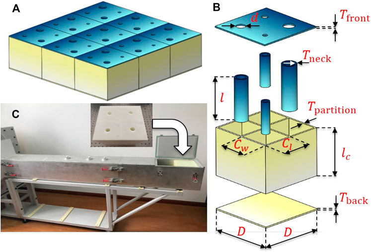
FIGURE 1. (A) Schematic of a metasurface absorber with nine supercells. (B) The explosive view of one supercell with four different unit cells. The thickness of the front panel,
Theoretical Model for a Single Resonant Unit Cell With the Embedded Neck
The Stinson’s model (Stinson and Shaw, 1985; Stinson, 1991; Huang et al., 2019), which is valid for a broad range of frequencies, is used to model the narrow neck with the visco-thermal loss effect taken into account. Therefore, we have the impedance for the cylindrical neck with a circular cross-section (Huang et al., 2019),
where
For resonant unit cells whose dimensions are all much smaller than the working wavelength, the impedance for the irregular-shape cavity resulted from the embedded neck can be approximated as (Huang et al., 2019),
where
The overall impedance of the resonator can be approximated as the sum of the impedances of the neck and cavity, which reads (Huang et al., 2019),
where the subscript n represents the neck and c represents the cavity.
Theoretical Model for Supercell With Different Unit Cells
When a supercell of the panel is composed of M different unit cells in parallel, its absorption performance can be characterized by a mean specific acoustic admittance or a mean specific acoustic impedance at normal incidence (Zwikker and Kosten, 1949),
where
For normal incidence, a perfect absorption requires an impedance match between the panel and the air,
Although this method is physically straightforward, computationally inexpensive and accurate for our deep-subwavelength structures, several underlying assumptions and limitations need to be noted. First, Eq. 5 can be assumed to be independent (Wang et al., 2014) of the azimuthal angle
Throughout this paper we will use a figure of merit
Causal Optimality in Sound Absorption
An absorber can be regarded as causally optimal when its thickness reaches the minimum limitation dictated by the principle of causality (Yang et al., 2017):
where
Results and Discussion
Design for 50–63 Hz (One-Third Octave) Absorption Without Optimization
Motivated by the application of modal frequency absorption, four different resonant unit cells arranged in a supercell, with parameters listed in Table 1, are realized, with
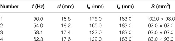
TABLE 1. Geometric parameters of the metasurface absorber with four different unit cells without optimization. The lateral size of the supercell is 20 cm
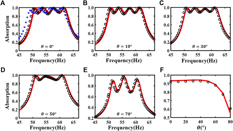
FIGURE 2. (A) The theoretical (red solid line), the first type of numerical (black circles) and experimental (blue crosses) absorption coefficient at normal incidence for the non-optimized metasurface absorber. (B–E) The theoretical and numerical absorption coefficient for the angles of incidence
The design principle of this absorber is described as follows. The lateral size of the supercell is fixed as
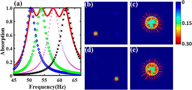
FIGURE 3. (A) The theoretical absorption coefficient of the non-optimized supercell (red solid line) and individual unit cells (blue diamonds, green circles, magenta points and black crosses are for unit cell one, two, three, and four respectively). The curve for “unit cell N” is an absorption spectrum for a metasurface in which only unit cell N can interact with the incident sound and all the other unit cells are blocked at the front panel. N = 1, 2, 3, 4. Sound intensity maps of the non-optimized supercell at (B) 53.6 Hz and (D) 57.8 Hz, respectively. The bottom-left unit cell of (B) and the bottom-right unit cell of (D) are enlarged, as shown in (C) and (E), respectively. The incident pressure is normalized to 1 Pa. Color bar (
To gain insights concerning how the supercell is behaving at these near-perfect absorption frequencies, the sound intensity fields just above the supercell surface are drawn at the resonant frequencies of two selected unit cells (53.6 and 57.8 Hz) using COMSOL in Figures 3B–E. At these resonant frequencies, the sound intensity is observed to be highly concentrated and drawn to the only unit cell whose mode is excited. Instead of “penetrating” the entire supercell and being absorbed by all the unit cells at a similar amount, the sound energy is dissipated mostly by one resonating unit cell while other unit cells behave in a way as if they were “sealed.” This is a clear signature of the weak coupling between the resonant unit cells at the resonant frequencies, and thus it confirms the validity to design each unit cell independently for a near-perfect absorption.
Design for 50–63 Hz (One-Third Octave) Absorption With Optimization
In the previous section, the achieved design for the desired absorption spectrum has room to shrink the thickness, considering several deficiencies during the design methodology. First, by assuming a weak coupling between unit cells, all unit cells in the previous section are designed independently to realize near-perfect absorption at their individual resonant frequencies to form a continuously high absorption spectrum. A better assignment of the contribution from all unit cells to the total absorption at each individual frequency of interest is left to be resolved. Second, the assignment of the cross-sectional area to each cavity follows an empirical idea: Generally, a larger cross-sectional area is required for a lower frequency if the cavities are required to have the same depth. A better assignment of cross-sectional areas also needs to be proposed. To address the two concerns above, the lateral areas of unit cells are assigned as additional variables to be treated in GA, while the thickness of the absorber is to be optimized for the same absorption spectrum, i.e.,
Figure 4 shows the absorption performance of the optimized design, which is 15.4 cm (1/44.5 of the wavelength at 50 Hz) and is 23% thinner than the non-optimized one, with the geometric parameters listed in Table 2. However, its average absorption performance is not sacrificed as shown from the comparison of two designs’ performance in Table 3. Note that the average frequency range for the analytical predictions and the numerical results is 50–63 Hz, while that for the experiment is 48–61 Hz because of the small frequency shift as shown in Figures 2A,4A. The larger mismatch between the experimental result and the analytical prediction of the optimized design, compared with that of the non-optimized design, can be reasonably explained by a larger fabrication error, as shown in Supplementary Appendix A. The maximum tolerance is 0.4 mm for the optimized sample, which is larger than that of the previous unoptimized sample, which is 0.1 mm.
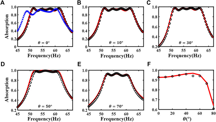
FIGURE 4. (A) The theoretical (red solid line), the first type of numerical (black circles) and experimental (blue cross) absorption coefficient at normal incidence for the optimized metasurface absorber. (B–E) The theoretical and numerical absorption coefficient for the angles of incidence
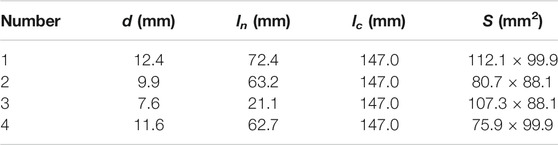
TABLE 2. Geometric parameters of the optimized metasurface absorber composed of four different unit cells. The lateral size of the supercell is
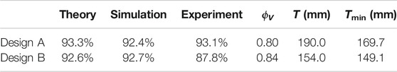
TABLE 3. Comparison of the absorption performance between the non-optimized (design A) and the optimized (design B) absorber. “Theory” and “Simulation” refer to the average absorption coefficients over 50–63 Hz based on the analytical model and the first type of numerical result, while “Experiment” refers to the average absorption coefficient over 48–61 Hz based on the experimental result.
Next, we will uncover how the supercell thickness can be reduced while the absorption performance is maintained. In contrast to the fairly weak coupling between unit cells demonstrated from the previous design at these near-perfect absorption points, a strong coupling, at which more than one unit cells jointly contribute to the total absorption, is observed as shown in Figure 5A. The intensity plots for the middle two peaks of the absorption curve (i.e., 54.4 and 57.8 Hz) are used to further shed light on the strong coupling. As shown in Figures 5B–D, two different unit cells are excited simultaneously and strongly coupled to work as energy sinks at 54.4 Hz. At 57.8 Hz, this phenomenon is not as pronounced as that at 54.4 Hz because the portion of absorption from one of the unit cells is large, as shown in Figures 5E–G. Theoretically speaking, the strong coupling is the interference of the reflected propagating waves from the simultaneously excited unit cells. The total reflected propagating wave is a linear combination of the reflected propagating waves from all the individual unit cells. Interference, a fundamental wave phenomenon, happens among these reflected propagating waves, which creates the ripples in the absorption spectrum of the supercell and even changes the number of absorption peaks (Figure 4F). Consequently, each individual unit cell is not required to satisfy the near-perfect absorption requirement (Huang et al., 2020) like shown in Figure 3. Moreover, the assignment of cross-sectional areas to these non-uniform cavities is judiciously tuned thanks to the assistance of GA. As shown in Table 2, for the unit cell one, which corresponds to the lowest resonant frequency, its cross-sectional area is
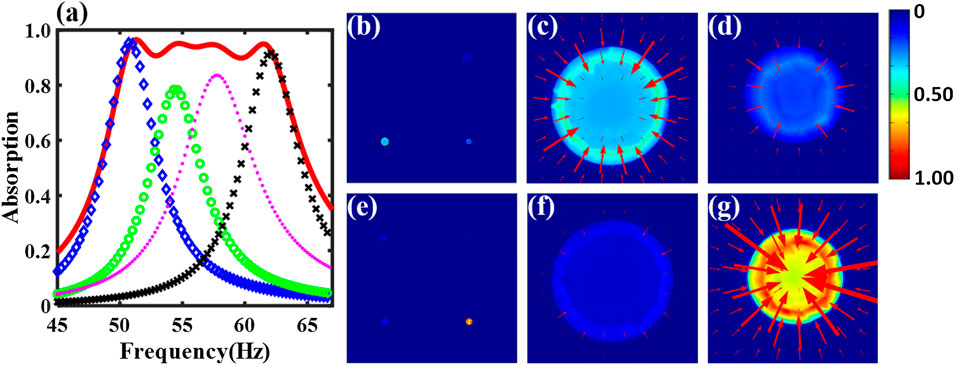
FIGURE 5. (A) The theoretical absorption coefficient of the optimized supercell (red solid line) and individual unit cells (blue diamonds, green circles, magenta points and black crosses are for unit cell one, two, three, and four respectively). The curve for “unit cell N” is an absorption spectrum for a metasurface in which only unit cell N can interact with the incident sound and all the other unit cells are blocked at the front panel. N = 1, 2, 3, 4. Sound intensity maps of the optimized supercell at (B) 54.4 Hz and (E) 57.8 Hz, respectively. The bottom-left unit cell and the bottom-right unit cell of (B) are enlarged, as shown in (C) and (D), respectively. The bottom-left unit cell and the bottom-right unit cell of (E) are enlarged, as shown in (F) and (G), respectively. The incident pressure is normalized to 1 Pa. Color bar (
The Hamiltonian from the coupled-mode theory (Suh et al., 2004; Verslegers et al., 2012) is likely another way to interpret the interference coupling in the far field (Lepetit and Kanté, 2014; Huang et al., 2020). Taking the system at the second absorption peak (i.e., at 54.4 Hz) of normal incidence as an example, two resonators are effectively excited so that the four-state system can be reduced to a two-state system at this frequency. This two-state system is coupled to one port since here only the plane wave mode exists in the far field under the cutoff frequency of the waveguide. Thus, the effective Hamiltonian of this two-states, one-port open system is written as (Suh et al., 2004; Verslegers et al., 2012; Lepetit and Kanté, 2014),
where
The Coupling Through the Evanescent Wave and Acoustic-Structure Interaction
Besides the interference coupling in the far field, there also exists two types of coupling mechanisms in our absorber within the frequency range of interest: the evanescent wave coupling on the top surface via air and the acoustic-structure interaction between cavities through partitions. In Figures 2,4, the first type of simulations has considered evanescent wave coupling but not the acoustic-structure interaction. To consider the acoustic-structure interaction, the second type of simulations is performed using the Thermoviscous Acoustic-Solid Interaction Module of COMSOL Multiphysics 5.4 with detailed settings in Supplementary Appendix B. The coupling effects that each model takes into account are summarized in Table 4. The absorption coefficient curves of different models for the non-optimized and the optimized design are plotted in Figures 6A–F. As shown in Table 4, the difference between the theoretical model and the first type of numerical simulation is that the former does not consider the evanescent waves while the latter does. The difference between the first and second type of numerical model is that the former does not consider the acoustic-structure interaction while the latter does. This means that we can separately evaluate the validation of the assumptions that are made in Theoretical Model for Supercell With Different Unit Cells about the evanescent wave and acoustic-structure interaction by comparing the results in Figure 6.
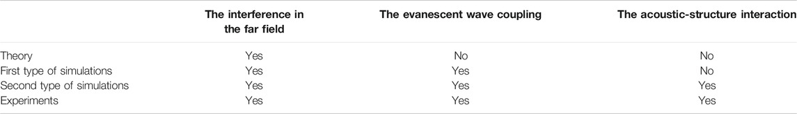
TABLE 4. The coupling effects that each model takes into account. By comparing the corresponding curves in Figure 6, the evanescent wave coupling and the acoustic-structure interaction can be separately evaluated for the validation of the assumptions that are made in the Theoretical Model for Supercell With Different Unit Cells.
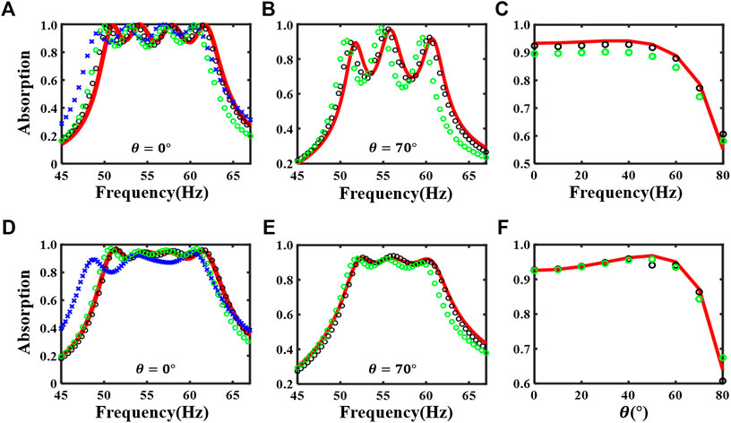
FIGURE 6. (A) The theoretical (red solid line), the first type of numerical (black circles), the second type of numerical (green circles) and experimental (blue cross) absorption coefficient at normal incidence. (B) The theoretical and the two types of numerical absorption coefficient for the angle of incidence
One observation of Figure 6 is that the positions of the peaks of the first type of numerical results are all slightly down-shifted from the theoretical predictions because of the coupling by the evanescent waves. This observation is consistent with the one in the supplementary material of (Yang et al., 2017) and shows that the coupling by the evanescent waves is negligible.
Another observation of Figure 6 is the redshift of the second type of numerical results compared with the first type of numerical results. This is consistent with the redshift of the experimental results compared with the first type of numerical results, and this is resulted from the relatively weak acoustic-structure interaction through the partitions. The weak acoustic-structure interaction could be explained as follows: First, whether the structural resonance happens within the frequency of interest is examined. We numerically calculate the modal frequencies of the whole structure. For the normal incidence case, the bottom surface and four side surfaces are assumed as fixed to mimic the boundary conditions in a waveguide. For the oblique incident cases, the bottom surface is assigned as fixed and the four side surfaces are assigned as the Floquet periodic condition. In all these cases, the lowest modal frequencies are around 800 Hz, which are beyond of the range of our interest. This means that no structural resonance occurs within the frequency range of interest so that the interaction between the neighboring cavities through the partition can be approximated as a transmission problem involving only acoustic waves. In this case, we can estimate the effect of the 5 mm partition by calculating its plane wave pressure transmission coefficient (material properties are in Supplementary Appendix A), which is approximately 8% at 50 Hz when the wave diction is perpendicular to the partition. This means that the impedance and the thickness of the partition are large enough that the transmission through the partition at the frequency range of interest is reasonably small. Thus, the acoustic-structure interaction manifests itself as a small sound transmission through the partition in our case, which effectively makes the cavity less stiff and consequently results in the redshift of the resonant frequency.
Based on the above analysis and observation, the analytical model, which does not consider the acoustic-structure interaction as well as the evanescent coupling, is acceptable as a simple model to design the absorber, as long as structural resonance is not excited and the impedance and thickness of the partition are large enough to effectively reduce the sound transmission.
Design for 50–100 Hz (One Octave) Absorption With Optimization
The optimized metasurface absorber, which benefits from the strong coupling between unit cells with judiciously designed cavities, is further explored to realize 50–100 Hz absorption. The lateral size of the supercell for an optimal design will be discussed below, instead of being assumed as
With the above concerns, GA is used as an efficient tool to seek an optimal design which satisfies
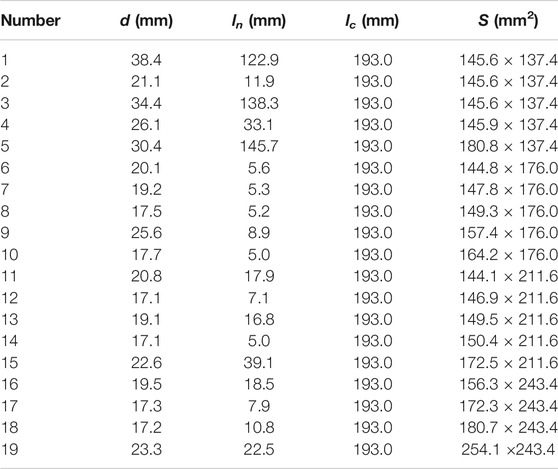
TABLE 5. Geometric parameters of an optimized metasurface absorber composed of 19 different unit cells. The lateral size of the supercell is 78.84 cm
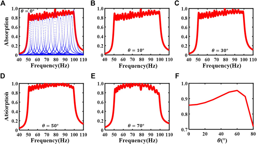
FIGURE 7. (A) The absorption coefficient of the optimized supercell (red solid line) and individual unit cells (blue points lines) at normal incidence. (B–E) The theoretical absorption coefficients for the angles of incidence
It is noted that the achieved design is causally optimal: If we insert the achieved absorption spectrum (the red curve in Figure 8) of our design and the corresponding volume porosity (90% for this design) into Eq. 7,
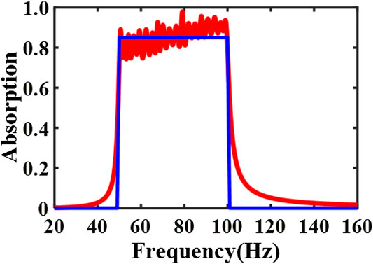
FIGURE 8. The absorption coefficient of the optimized supercell (red solid line) and the ideal absorber (blue solid line) at normal incidence. The optimal thickness for the optimized design is 20 cm. The optimal thickness for the ideal design is 16.9 cm when the volume porosity is set as one and the achieved absorption spectrum exactly matches with the desired one (85% over 50–100 Hz) in Eq. 7.
Next, we will uncover how the two additional design variables, like the geometric parameters of all unit cells, play critical roles in reaching the causally optimal design (the minimum thickness) for a desired absorption spectrum. For the lateral size of supercell being a suitable value, on one hand, it should be as large as possible so that the lateral size of unit cells can be larger and therefore the thickness of all unit cells can be smaller to meet the design objective. On the other hand, it cannot be too large because that will result in an impedance-mismatch for individual unit cells and thus a drop of absorption coefficient. The number of unit cells should also be properly chosen. If the number of unit cells is too small, it would be insufficient to achieve such a broad absorption spectrum by coupling. However, if the number of unit cells is too large and the thickness is preserved, it would call for an increased lateral size of the supercell, which would result in a reduction of the impedance match and the absorption performance. Similarly, for such a case of a large number of unit cells, if the lateral size of the supercell is chosen to be preserved for the desired absorption performance, it would result in an increase in the thickness of the supercell.
In addition, we would like to further comment on the impact of the causality constraint on guiding the thinnest design of the linear and passive absorber for a desired absorption spectrum. First, it is not difficult to design an absorber which is causally optimal as indicated in the supplemental material of reference (Yang et al., 2017): The MPP or sponge can easily become causally optimal if the desired absorption is not required to be high over a broad low frequency range. However, it is hard to realize a high absorption at such a low-frequency and broad range as presented in the paper, i.e., 50–100 Hz. Second, as shown in Eq. 7, the optimal thickness not only relies on the achieved absorption spectrum, but also is highly dependent on the volume porosity. The larger the volume porosity is, the smaller the optimal thickness is. In other words, a better space utilization makes an absorber thinner. A higher volume porosity (
Conclusion
This paper analytically, numerically and experimentally studies a low-frequency broadband (50–63 Hz, one third octave band), high absorption (average absorption coefficient
Data Availability Statement
The raw data supporting the conclusion of this article will be made available by the authors, without undue reservation.
Author Contributions
JJ and DL contributed equally to this work.
Conflict of Interest
The authors declare that the research was conducted in the absence of any commercial or financial relationships that could be construed as a potential conflict of interest.
Acknowledgments
YL acknowledges support from the National Natural Science Foundation of China under Grant No. 11704284.
Supplementary Material
The Supplementary Material for this article can be found online at: https://www.frontiersin.org/articles/10.3389/fmech.2020.586249/full#supplementary-material
References
Assouar, B., Liang, B., Wu, Y., Li, Y., Cheng, J.-C., and Jing, Y. (2018). Acoustic metasurfaces. Nat Rev Mater 3 (12), 460–472. doi:10.1038/s41578-018-0061-4
Błaszak, M. A. (2008). Acoustic design of small rectangular rooms : normal frequency statistics. Appl. Acoust. 69, 1356–1360. doi:10.1016/j.apacoust.2007.10.005
Cai, X., Guo, Q., Hu, G., and Yang, J. (2016). Ultrathin low-frequency sound absorbing panels based on coplanar spiral tubes or coplanar Helmholtz resonators. Appl. Phys. Lett. 105 (12), 121901. doi:10.1063/1.4895617
Cox, T., and D’Antonio, P. (2016). Acoustic absorbers and diffusers: theory, design and application. 3rd Edn. Boca Raton, FL: CRC Press.
Ding, K., Ma, G., Xiao, M., Zhang, Z. Q., and Chan, C. T. (2016). Emergence, coalescence, and topological properties of multiple exceptional points and their experimental realization. Phys. Rev. X 6 (2), 1–13. doi:10.1103/PhysRevX.6.021007
Donda, K., Zhu, Y., Fan, S.-W., Cao, L., Li, Y., and Assouar, B. (2019). Extreme low-frequency ultrathin acoustic absorbing metasurface. Appl. Phys. Lett. 115 (17), 173506. doi:10.1063/1.5122704
Fuchs, H. V., Zha, X., Zhou, X., and Drotleff, H. (2001). Creating low-noise environments in communication rooms, Appl. Acoust. 62, 1375–1396. doi:10.1016/s0003-682x(01)00008-1
Ge, H., Yang, M., Ma, C., Lu, M.-H., Chen, Y.-F., Fang, N., et al. (2018). Breaking the barriers: advances in acoustic functional materials. Natl. Sci. Rev. 5 (2), 159–182. doi:10.1093/nsr/nwx154
Gerard, N. J. R. K., and Jing, Y. (2019). Loss in acoustic metasurfaces : a blessing in disguise. MRS Commun. 10 (1), 32–41. doi:10.1557/mrc.2019.148
Huang, S., Fang, X., Wang, X., Assouar, B., Cheng, Q., and Li, Y. (2018). Acoustic perfect absorbers via spiral metasurfaces with embedded apertures. Appl. Phys. Lett. 113 (23), 233501. doi:10.1063/1.5063289
Huang, S., Fang, X., Wang, X., Assouar, B., Cheng, Q., and Li, Y. (2019). Acoustic perfect absorbers via Helmholtz resonators with embedded apertures. J. Acoust. Soc. Am. 145 (1), 254–262. doi:10.1121/1.5087128
Huang, S., Liu, T., Zhou, Z., Wang, X., Zhu, J., and Li, Y. (2020). Extreme sound confinement from quasibound states in the continuum. Phys. Rev. Appl. 14 (2), 1. doi:10.1103/physrevapplied.14.021001
Huang, S., Zhou, Z., Li, D., Liu, T., Wang, X., Zhu, J., et al. (2020). Compact broadband acoustic sink with coherently coupled weak resonances. Sci. Bull. 65 (5), 373–379. doi:10.1016/j.scib.2019.11.008
Jiménez, N., Romero-García, V., Pagneux, V., and Groby, J.-P. (2017). Rainbow-trapping absorbers: broadband, perfect and asymmetric sound absorption by subwavelength panels for transmission problems. Sci. Rep. 7 (1), 13595. doi:10.1038/s41598-017-13706-4
Kim, S., Kim, Y.-H., and Jang, J.-H. (2006). A theoretical model to predict the low-frequency sound absorption of a Helmholtz resonator array. J. Acoust. Soc. Am. 119 (4), 1933–1936. doi:10.1121/1.2177568
Kim, Y.-H. (2010). “Essentials of acoustics in a closed space,” in Sound propagation: an impedance based approach (Singapore: John Wiley & Sons), Chap. 5, Vol. 9, 323–334.
Lau, S.-K., and Powell, E. A. (2018). Effects of absorption placement on sound field of a rectangular room: a statistical approach. J. Low Freq. Noise Vib. Act. Contr. 37 (2), 394–406. doi:10.1177/1461348418780027
Lee, T., and Iizuka, H. (2018). Heavily overdamped resonance structurally engineered in a grating metasurface for ultra-broadband acoustic absorption. Appl. Phys. Lett. 113 (10), 101903. doi:10.1063/1.5047798
Lee, T., and Iizuka, H. (2019). Acoustic resonance coupling for directional wave control: from angle-dependent absorption to asymmetric transmission. New J. Phys. 21 (4), 043030. doi:10.1088/1367-2630/ab130d
Lepetit, T., and Kanté, B. (2014). Controlling multipolar radiation with symmetries for electromagnetic bound states in the continuum. Phys. Rev. B 90 (24), 1–4. doi:10.1103/PhysRevB.90.241103
Leroy, V., Strybulevych, A., Lanoy, M., Lemoult, F., Tourin, A., and Page, J. H. (2015). Superabsorption of acoustic waves with bubble metascreens. Phys. Rev. B 91 (2). doi:10.1103/PhysRevB.91.020301
Li, J., Wang, W., Xie, Y., Popa, B.-I., and Cummer, S. A. (2016). A sound absorbing metasurface with coupled resonators. Appl. Phys. Lett. 109 (9), 091908. doi:10.1063/1.4961671
Li, Y., and Assouar, B. M. (2016). Acoustic metasurface-based perfect absorber with deep subwavelength thickness. Appl. Phys. Lett. 108 (6), 063502. doi:10.1063/1.4941338
Liu, C. R., Wu, J. H., Chen, X., and Ma, F. (2019). A thin low-frequency broadband metasurface with multi-order sound absorption. J. Phys. D Appl. Phys. 52 (10), 105302. doi:10.1088/1361-6463/aafaa3
Maa, D.-Y. (1998). Potential of microperforated panel absorber. J. Acoust. Soc. Am. 104 (5), 2861–2866. doi:10.1121/1.423870
Ma, G., and Sheng, P. (2016). Acoustic metamaterials: from local resonances to broad horizons. Sci. Adv. 2 (2), e1501595. doi:10.1126/sciadv.1501595
Mei, J., Ma, G., Yang, M., Yang, Z., Wen, W., and Sheng, P. (2012). Dark acoustic metamaterials as super absorbers for low-frequency sound. Nat. Commun. 3. doi:10.1038/ncomms1758
Mosa, A. I., Putra, A., Ramlan, R., Prasetiyo, I., and Esraa, A.-A. (2019). Theoretical model of absorption coefficient of an inhomogeneous MPP absorber with multi-cavity depths. Appl. Acoust. 146, 409–419. doi:10.1016/j.apacoust.2018.11.002
Nark, D. M., Jones, M. G., and Sutliff, D. L. (2018). “Broadband inlet liner design for the DGEN aero-propulsion research turbofan,” 2018 AIAA/CEAS Aeroacoustics Conference, Atlanta, Georgia, June 25–29, 2018.
Ni, S. (2017). Sound-proof sandwich panel design via metamaterial concept. PhD dissertation. Raleigh (NC): North Carolina State University.
Panton, R. L., and Miller, J. M. (1975). Resonant frequencies of cylindrical Helmholtz resonators. J. Acoust. Soc. Am. 57 (6), 1533–1535. doi:10.1121/1.380596
Peng, X., Ji, J., and Jing, Y. (2018). Composite honeycomb metasurface panel for broadband sound absorption. J. Acoust. Soc. Am. 144 (4), EL255–EL261. doi:10.1121/1.5055847
Rivet, E., Boulandet, R., Lissek, H., and Rigas, I. (2012). Study on room modal equalization at low frequencies with electroacoustic absorbers, Acoustics 2012, Nantes, France, Apr 2012. hal-00810955, pp. 2851–2856.
Romero-Garciá, V., Theocharis, G., Richoux, O., Merkel, A., Tournat, V., and Pagneux, V. (2016a). Perfect and broadband acoustic absorption by critically coupled sub-wavelength resonators. Sci. Rep. 6 (1), 19519. doi:10.1038/srep19519
Romero-García, V., Theocharis, G., Richoux, O., and Pagneux, V. (2016b). Use of complex frequency plane to design broadband and sub-wavelength absorbers. J. Acoust. Soc. Am. 139 (6), 3395–3403. doi:10.1121/1.4950708
Simon, F. (2018). Long elastic open neck acoustic resonator for low frequency absorption. J. Sound Vib. 421, 1–16. doi:10.1016/j.jsv.2018.01.044
Stinson, M. R. (1991). The propagation of plane sound waves in narrow and wide circular tubes, and generalization to uniform tubes of arbitrary cross-sectional shape. J. Acoust. Soc. Am. 89 (2), 550–558. doi:10.1121/1.400379
Stinson, M. R., and Shaw, E. A. G. (1985). Acoustic impedance of small, circular orifices in thin plates. J. Acoust. Soc. Am. 77 (6), 2039–2042. doi:10.1121/1.391776
Suh, W., Wang, Z., and Fan, S. (2004). Temporal coupled-mode theory and the presence of non-orthogonal modes in lossless multimode cavities. IEEE J. Quant. Electron. 40 (10), 1511–1518. doi:10.1109/JQE.2004.834773
Uno, I. (2010). “Mathematical supplement,” in Noise reduction analysis (Sudbury, MA: Jones & Barlett Publishers), Chap. 4, Vol. 5, 133–135.
Verslegers, L., Yu, Z., Ruan, Z., Catrysse, P. B., and Fan, S. (2012). From electromagnetically induced transparency to superscattering with a single structure: a coupled-mode theory for doubly resonant structures. Phys. Rev. Lett. 108 (8), 1–5. doi:10.1103/PhysRevLett.108.083902
Wang, C., and Huang, L. (2011). On the acoustic properties of parallel arrangement of multiple micro-perforated panel absorbers with different cavity depths. J. Acoust. Soc. Am. 130 (1), 208–218. doi:10.1121/1.3596459
Wang, C., Huang, L., and Zhang, Y. (2014). Oblique incidence sound absorption of parallel arrangement of multiple micro-perforated panel absorbers in a periodic pattern. J. Sound Vib. 333 (25), 6828–6842. doi:10.1016/j.jsv.2014.08.009
Wang, X., Fang, X., Mao, D., Jing, Y., and Li, Y. (2019). Extremely asymmetrical acoustic metasurface mirror at the exceptional point. Phys. Rev. Lett. 123 (21), 214302. doi:10.1103/PhysRevLett.123.214302
Weston, D. E. (1953). The theory of the propagation of plane sound waves in tubes. Proc. Phys. Soc. B 66 (8), 695–709. doi:10.1088/0370-1301/66/8/310
Yang, M., Chen, S., Fu, C., and Sheng, P. (2017). Optimal sound-absorbing structures. Mater. Horiz. 4 (4), 673–680. doi:10.1039/c7mh00129k
Yang, M., Meng, C., Fu, C., Li, Y., Yang, Z., and Sheng, P. (2015). Subwavelength total acoustic absorption with degenerate resonators. Appl. Phys. Lett. 107 (10), 104104. doi:10.1063/1.4930944
Yang, M., and Sheng, P. (2017). Sound absorption structures: from porous media to acoustic metamaterials keynote topic. Annu. Rev. Mater. Res. 47 (1), 83–114. doi:10.1146/annurev-matsci-070616-124032
Zhu, Y., Donda, K., Fan, S., Cao, L., and Assouar, B. (2019). Broadband ultra-thin acoustic metasurface absorber with coiled structure. APEX 12, 114002. doi:10.7567/1882-0786/ab494a
Keywords: low-frequency sound absorption, broad bandwidth, deep-subwavelength thickness, far-field coupling effect, causal optimality
Citation: Ji J, Li D, Li Y and Jing Y (2020) Low-Frequency Broadband Acoustic Metasurface Absorbing Panels. Front. Mech. Eng. 6:586249. doi: 10.3389/fmech.2020.586249
Received: 22 July 2020; Accepted: 05 October 2020;
Published: 18 November 2020.
Edited by:
Oscar Vazquez Mena, University of California, San Diego, United StatesReviewed by:
Mariana Amorim Fraga, Federal University of São Paulo, BrazilAurélien Merkel, Université de Lorraine, France
Copyright © 2020 Ji, Li, Li and Jing. This is an open-access article distributed under the terms of the Creative Commons Attribution License (CC BY). The use, distribution or reproduction in other forums is permitted, provided the original author(s) and the copyright owner(s) are credited and that the original publication in this journal is cited, in accordance with accepted academic practice. No use, distribution or reproduction is permitted which does not comply with these terms.
*Correspondence: Yun Jing, amluZy55dW5AcHN1LmVkdQ==