 Josephus J. M. Driessen
 Romeo Orsolino
- 1Deptartment Rehab Technologies`Istituto Italiano di Tecnologia (IIT), Genoa, Italy
- 2Dynamic Robot Systems (DRS) Group, Oxford Robotics Institute (ORI), University of Oxford, Oxford, United Kingdom
This manuscript presents a method to calculate and analyze mechanical shock of a multi-rigid body system, based on the revised concept of the center of percussion and a newly derived variable called the radius of percussion. The objective is to improve the mechanism’s robustness against mechanical shocks that are caused by certain impacts, such as those experienced by legged robots from landing a jump or making a step. In practice, it can be used for placement of shock-sensitive components in robots, such as inertial measurement units and cameras, and for mechanical and controller design improvements and optimizations that aim to reduce shock in certain body parts. Several case studies are presented to support the usefulness of the theory.
1 Introduction
Legged robots research involves experimental hardware, which is often troubled by practical issues owing to the robot’s lack of robustness (Driessen, 2019). This leads to frequent breakdown of parts or to the requirement of tools that impede, hinder or alter the robot’s end user scenario, such as harnesses, tethers, booms and soft environments. These deficiencies prompt additional costs, delays and ineffective progress. Especially recent legged robot research has popularized and progressed significantly in the development of robots that exhibit highly dynamic behavior, referring to various quadrupeds (Hutter et al., 2016; Kenneally et al., 2016; Bledt et al., 2018; Kim et al., 2019; Boston Dynamics, 2020; Unitree, 2020), the bipedal Cassie and Digit (Agility Robotics, 2020), the monopedal jumping robots Salto (Yim and Fearing, 2018) and conceptual Skippy (Driessen, 2019). Respective research has primarily focused on improving mechanical design, intelligence and motor skills for the purpose of maximizing physical performance. Achievements of these primary objectives intensify the need to address the (secondary objective of) robustness of these machines to ensure their survivability.
Robustness can refer to physical robustness, which includes the ability to withstand mechanical impacts, and behavioral robustness, which refers to the ability to respond to disturbances. Especially the subject of controllability is a popular and challenging subject in legged robotics (Wieber et al., 2016), and have led to the introduction of disturbance rejection measures to quantify the performance of controllers, such as the gait sensitivity norm (Hobbelen and Wisse, 2007). Both physical and behavioral robustness are synergetic and share the goal of improving a robot's survivability; for example, a robot that falls less frequently (behavioral robustness) but is also able to survive the few remaining falls (physical robustness) could continue to perform the task it was designed for, and could hence be considered robust.
Robustness of a robot can furthermore be categorized by desired actions (taken by the control policy), such as those caused by making a step, and undesired actions, such as those caused by a fall. Control strategies that aim to soften feet impact (Sato and Ohnishi, 2005) or joint impact after landing (Hidaka et al., 2020) are examples of improving a robot’s behavioral robustness against desired actions, and those that focus on disturbance rejection or detection (Mummolo et al., 2017) and action upon falling (Fujiwara et al., 2004) are examples of improving a robot’s behavioral robustness against undesired actions. The use of series elastic actuators (Pratt and Williamson, 1995) and soft or flexible feet and limbs (Zhou and Bi, 2012) are examples of improving a robot’s physical robustness against desired actions, and equipping the robot with shock-absorbing roll-cages (Kovač et al., 2009), foam (Schuitema, 2012) or tailored flexible bumper covers (Battaglia et al., 2009) are examples of improving a robot’s physical robustness against undesired actions. However, series elastic actuators mainly protect the drive train of the actuator, not necessarily other robot parts they connect to. Moreover, the flexible technology used in series elastic actuators and protective bumpers are not always usable on feet of legged robots to protect them against desired impacts, because their associated softness impairs the bandwidth and performance of the balance controllers. With the increasing growth of legged robots that exhibit highly dynamic behavior and utilize more demanding control strategies, robustness will have to be improved through means other than physical softness.
This manuscript focusses on improving a legged robot’s robustness against the desired action of making a step or landing a jump, based on an analysis of shock propagation, through the introduction of a method that calculates and visualizes this shock propagation. Both the robot’s physical and behavioral robustness can be improved by such an analysis. Reducing the shocks in certain areas of the robot, either through design or control, also makes its components less likely to get loose or fail from fatigue. Our proposed theory can also be used to tactically place shock-sensitive components in those areas of the robot that are subject to less or even zero shock. Such a component can be the inertial measurement unit (IMU) or a camera, whose performance deteriorate for high velocities or accelerations. For example, IMUs are known to saturate at low accelerations (typically 16 g (Vectornav, 2009)), which is likely to hinder the performance of the state estimator and could destabilize a dynamic robot.
The presented method is based on impulsive dynamics of rigid-multi body systems, which requires less information about the system and is less computationally expensive than finite-element methods (FEM). This makes our proposed shock analysis a good candidate to draw lessons about a robot design from its very earliest stages.
In particular, the presented theory is largely inspired from the concept of the center of percussion (CoPc), which is a popular term in mechanics of bat-and-ball games and racket sports (Ficken, 1976; Cross, 2004; Raychowdhury and Boyd, 1979; Brody, 1979), to describe the point on a bat or racket that produces no reactive shock at the handle when striking a ball. The CoPc is also associated with temporal behavior of pendulums, to describe equivalence with point-mass models. This use has also been applied to legged robot control (Alba et al., 2010), but is not further related to the work in this manuscript.
The contributions of this manuscript can be summarized as follows:
• Addressing the importance of expressing shock not only with the CoPc, but also by how shock expands from the CoPc, with a newly introduced term called the radius of percussion (RoPc) (Section 2).
• Presenting a 3-step method to calculate shock in any 3D rigid-body-system, which for planar studies can be expressed in the CoPc and RoPc for every body (Section 3).
• Suggesting various applications that require the improvement of the robot's robustness against desired actions, such as placement of shock-sensitive components and reducing shock propagation through design and control (Section 4).
2 Expressing Shock of a Single Body
The impact that results from striking an unconstrained rigid body is a translational impulse that results in a shock: a peak acceleration, which could be perceived as an instantaneous change of velocity. This shock is purely translational only if the impact is applied at the center of mass (CoM), but otherwise has both translational and angular components. For the planar case, these can be described by the CoPc and the proposed RoPc.
2.1 Revising the Center of Percussion
In 2D, both the translational and angular components of shock can—just like velocity and acceleration—be described by a pure rotation about a point in the plane of the body, which shall be referred to as point P. This point is of interest because it experiences no translational shock, i.e., no instantaneous change of linear velocity. Shock can also be described for bodies in 3D, for which shock in the most general case has no point of zero translational shock. In the most general 3D case, there is an axis of minimum—but not zero—shock.1 However, in legged robots, it is often possible to find a plane where most of the dynamics take place. In particular, the most common types of legged locomotion occur in the sagittal plane (walking, running, etc.), and as such, also most of the impacts will occur in the plane. Note that even a lot of specialized gaits, such as side stepping, mostly take place in a plane, albeit a different one. For these reasons, a planar analysis usually suffices, which allows shock to be expressed in a more tangible way. As such, the content of this manuscript focusses on the planar case, unless otherwise specified. Notwithstanding, as will become evident from the method presented in Section 3, it is still possible to perform a 3D shock analyses if so desired for special actions.
If the body were freely pivoted at a point O and if O coincided with the point that experiences no translational shock P, the pivot would not experience any reaction impulse from the impact, and the corresponding point of the applied impact would be referred to as the center of percussion (CoPc) for that pivot (Ficken, 1976; Brody, 1979; Raychowdhury and Boyd, 1979; Cross, 2004).
For bodies that are assumed to receive an impact from a predefined direction and that have a designated pivot, the CoPc is a fixed point on that body. This is the case for bats and tennis rackets, which are slender bodies that are assumed to receive an impact perpendicular to their major axis and for which the designated pivot is their handle. However, for a general planar rigid body the CoPc is a function of the pivot point and the line of action of the impact. In particular, the CoPc lies on the intersection of the line of action of the impact and the line perpendicular to it that passes through the pivot.
The case of a slender body is visualized in Figure 1, which shows the reactive shock or initial response of a slender beam with a uniform mass distribution freely hinged to a pivot and a frictionless and massless slider that operates perpendicular to the extension of the beam after impacting it at a designated point (indicated ). An impact at the CoPc (indicated  ) leads to no reactive shock on the slider (beam C), whereas an impact anywhere else does, of which the special case an impact at the CoM (indicated ), which leads to a pure translational shock (beam A).
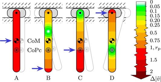
FIGURE 1. A slender beam suspended from a pivot on a frictionless and massless slider, with the CoM ( ) at
) at  ) at
) at
For this case, it can be derived that the CoPc can be calculated as
c and p are the (1D) coordinates of the body’s CoM and CoPc along the axis of the body, with respect to the pivot point O;
Eq. 1 exposes several noteworthy properties of the CoPc:
• The magnitude of the applied impulse does not appear in the equation, which implies that it is irrelevant.
• From the fact that I and m are strictly positive, it follows that the pivot and CoPc must be on opposing sides of the CoM.
• c and p can be interchanged: if an impulse is applied at the unconstrained pivot point, then no reactive shock is produced at the CoPc, as can also be seen in Figure 1 (beam D).
The interchangeability follows from the fact that Eq. 1 describes an impulsive equilibrium and that momentum must be conserved. Technically, this also allows the CoPc to be defined as the point on a body that receives no shock as a result of an impact applied at O. The CoPc then corresponds to point P. In the remainder of this manuscript, the term CoPc of a body refers to this point P: the point of a body that does not experience translational shock as a result of the impulse applied to its joint(s) or end effector with which the body makes contact with other bodies or the environment.
2.2 Radius of Percussion
For design purposes it is also of interest how shock is experienced in the rest of the body, especially in the vicinity of the CoPc, because it is a function of the applied impulse and not guaranteed to be located at a practical point. Since shock can be expressed as a pure rotation about the CoPc, the absolute translational shock
Instead of using the rotational shock component as the variable to describe the rate of growth of the experienced translational shock, an arguably more tangible variable to do so is the radius from the CoPc at which the experienced shock is equal to the applied shock. This radius shall be referred to as the radius of percussion (RoPc)
where
For the treated case of a single body, it can be derived that
by solving
The shock profile of a single body is fully described by the CoPc and RoPc, and Eqs 1–3 well describe their behavior to changes of the applied impulse. The calculation and analysis of the shock profile of a multi-rigid-body system is less trivial. The method introduced in the following section is purposed to simplify and automate this calculation.
3 Shock Propagation in Robots
The full shock profile of a planar multi-rigid-body system that follows from an applied external shock—such as that resulting from a landing impact—is described by coordinates of the CoPc’s
(1) Solving the impulsive equation of motion (EoM) for the applied shock, described as an impact velocity, which typically returns the instantaneous change of independent joint velocity variables
(2) Calculating from
(3) Deducting the CoPc P (expressed in local body coordinates) and RoPc
Techniques for completing each of above steps are elucidated separately below. Each step is also applicable to spatial dynamics, except for the final step, which is tasked to calculate the desired planar CoPc and RoPc from the spatial shock vector
3.1 Impulsive Equation of Motion
The EoM of a multi-rigid-body system can be written in the canonical form
in which the subscripts
Recall from Section 2 that only the location and direction of the applied shock matter, not its magnitude. If the impact is directly applied at one or multiple joints that are orthogonal to each other, then the impact velocity
3.1.1 Dependent Joint Variables
Remember that Eqs 4–6 are only valid when joint variables
3.1.2 Gearbox Inertia
The above calculations have not addressed the effect of gearbox and rotor inertia of actuated joints. Whereas in theory they can be included as terms of reflected inertia or constrained inertial bodies in the EoM, in most cases this will likely not be necessary and lead to unrealistic results. Robots that are subject to a lot of shock are typically designed with series elasticity, in which case gearbox and rotor inertia have no effect on impulsive dynamics. If instead there is no series elasticity, then the gearbox likely still offers enough friction not to move at impact, at which point the bodies to which the gearbox connect should be considered as one.
3.2 Shock in Body Coordinates
The next step is to calculate both angular and translational components of the shock in body coordinates
where
The change of global velocity in body coordinates of a body
where
Since
which directly gives us the shock in body coordinates with respect to the global, from which the CoPc and RoPc can be calculated.
3.3 CoPc and RoPc
The translational velocity
where
In 2D we have
For
which is defined as long as
The RoPc
The appearance of the impact velocity on the various body diagrams throughout the manuscript), which would equal
Having found P and
3.4 Properties of Shock Propagation
The properties of shock of a single body can be well derived and understood from the algebraic expressions presented in Section 2. However, understanding shock propagation of multi-rigid-body systems is more convoluted due to the impracticality of algebraic descriptions and the large number of parameters and states, which promotes case-by-case studies. Nevertheless, several recurring properties of shock propagation in multi-rigid-body robots can be derived and observed, some of which are reminiscent from those discussed in Section 2:
• If the robot is moving forward, the CoPc of the body receiving the impact (e.g., a lower leg) will typically be on the front side of that body as well. In line with explanations of Section 2, this follows because the CoPc must be located on a line that is perpendicular to the applied impact and passes through the point of impact, which now acts as a pivot. Since the impact direction is typically pointing backwards if the robot is moving forwards, it follows that if the CoPc is above ground, it must also be on the front side.
• Upper bodies (i.e., those further down the chain from the impacted body) are generally subject to less shock. Correspondingly, the CoPc of bodies tend to move toward the next joint in the chain. Two bodies that are hinged approximately perpendicular to each other can contribute significantly to mitigating shock propagation. In fact, it can be deduced that it is possible to make a design that allows for complete elimination of shock from further propagating into the robot (Singh and Featherstone, 2020), which requires the CoPc to coincide with the next joint. In particular, two slender bodies that are properly hinged perpendicularly can each mitigate one of two translational components of the shock. In practice however, this objective might not be viable, as it imposes design and control constraints, requiring substantial mass of the body to be located on the other side on one of its joints, and the bodies to be exactly perpendicular to each other at impact.
• The above also implies that the effect of states The above also implies that the effect of states The above also implies that the effect of states and properties of upper bodies (i.e., those further down the chain) on lower ones, is minimal as long as the upper bodies receive little shock, and would in fact be zero for the above mentioned theoretical case if shock was completely eliminated. This suggests that upper bodies need not be accurately modeled to analyze shock of lower bodies.
• For a body at the end of the chain, the distance of the CoPc along the axis passing through its parental joint and its CoM can be calculated using Eq. 1. This implies it is at
Whereas the above assessments reveal some properties and behavior of shock propagation, case-by-case studies will nonetheless be necessary to fully define and quantify it. The following section showcases the presented analysis with case studies of realistically proportioned legged robots.
4 Case Study Results
This section describes three theoretical case studies that apply the method described in Sections 2 and 3 on legged robot models to analyze shock propagation. The first and the third case studies are open ended, featuring a generic robot leg and a quadruped respectively, and are tasked with clarifying shock propagation in a practical manner and with demonstrating the possible uses of analyzing it. The second case study focusses on the particular design of the hopping and balancing robot Skippy (Driessen, 2019), for purposes of IMU placement, of which the presented work has been inspired and sourced.
In all case studies, the shock is visualized using the same color map as defined in Figure 1, where shock is normalized by the impact velocity
4.1 Human(oid)/Prosthetic Leg
This case study considers a generic robot leg that could be part of a humanoid or a human with an above-knee prosthetic leg, making a step, as depicted in Figure 2 (cases A, B and C). The basic dynamic model is essentially a double pendulum, consisting of only the upper and lower leg segments. This model has also been amended with two additional bodies. The first includes a torso (cases D and E) and the second includes—in addition to the torso—also a foot (case F). The models have been dimensioned anthropomorphically. All bodies are modeled as slender beams with a uniform mass distribution (like in Section 2), and all joints are revolute. The leg segments are of equal length with a uniform mass distribution, with the upper leg being twice as heavy as the lower leg. The torso has
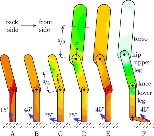
FIGURE 2. Typical shock scenarios of a step made with a robot leg that could be part of a humanoid or human with prosthesis (A: walking, B: running, C: stair climbing). Shock is shown to be less in certain areas of the robot, which can be utilized for placement of shock-sensitive components, and can be further reduced by increasing the strike angle. In addition, the effect of upper body dynamics on the lower bodies is low, especially as the upper body is not subject to a significant shock (C vs. D). Shock can furthermore be reduced substantially by landing on the toes of a foot instead of landing on the heel (E vs. F).
Following the steps described in Section 3, shock propagation is calculated and depicted in Figure 2 for several scenarios. In all cases, the upper leg is rotated with 15° with respect to the vertical, and the torso with −5°. The applied impact vector is also depicted for every case, which is typically pointing backwards (toward the left in the figure) during forward gaits. Its angle with respect to the vertical is referred to as the strike angle θ.4 Cases A, B and C differ only from the strike angle, each of which could be reminiscent of a different type of gait, namely walking, running and (stair) climbing respectively. Note that typically in running both the leg and impact vector can be more rotated, corresponding to a strike angle of ca. 60° as reported by Heidenfelder et al. (2008). However, note that for impulsive dynamics the orientation of the ground is irrelevant, as long as the robot does not slip: what matters is the robot’s orientation with respect to the direction of the impact vector. In stair climbing and other sloped gaits, the strike angle has been observed to be 75° and higher (Ojeda et al., 2017).
For all cases, the CoPc of the lower leg is observed to be in the front side (i.e., the right side in the figure) of the body, as related to the impact vector pointing back- (i.e., left) and upward with respect to the lower leg, as explained in Section 3.4. Further flattening the impact vector typically brings the CoPc closer to the physical body. Case F shows the effect of equipping the humanoid with a foot and ankle joint, and landing on the ball instead of heel of the foot. The ankle is rotated 75° with respect to the lower leg; the two are thus nearly perpendicular. It can be observed that the differences between case E and F are substantial: all the links of the considered robot largely benefit from the presence of the foot, with shock reduction exceeding 80%.
Lastly, as described in Section 3.4, the effect of dynamics of upper bodies on lower ones is minimal, as can be seen by comparing case studies C and D. This suggests that if shock in legs is to be analyzed, modeling them in isolation is a reasonable approach if little is known about the properties or behavior of the torso. This could be of special interest for the design of prosthetic legs, also considering the fact that the biological hip joint is significantly softer than a hardened steel knee joint. For example, Figure 3 shows a suggested relocation of the IMU on a research prototype that could lead to a significant performance boost regarding shock sensitivity, without requiring a major overhaul of the design.
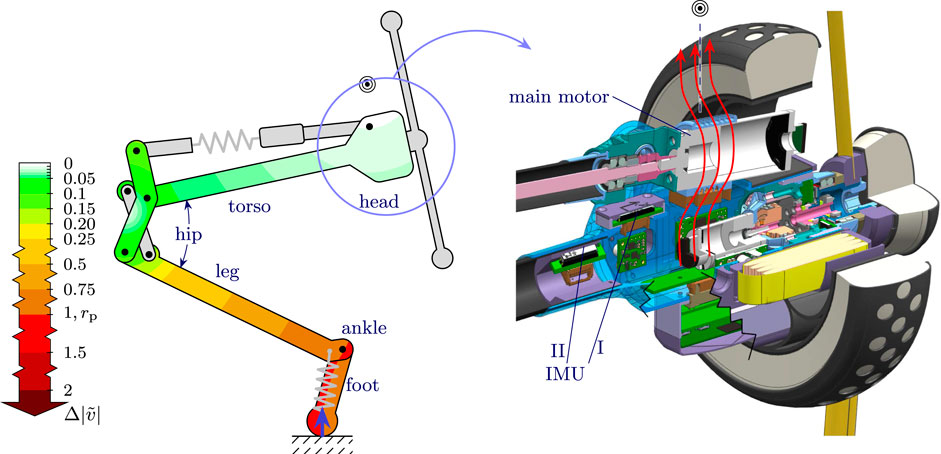
FIGURE 3. Skippy’s torso’s CoPc ( ) for a vertical landing is shown to be inconveniently above the motor’s heat stream for IMU placement. Nevertheless, the overall low shock experienced by the torso (high RoPc) allow for the IMU to be placed in a location (I or II) where it experiences less than 2% of the impact shock when landing a vertical jump.
4.2 Skippy
The Skippy robot is of particular interest for shock analysis, since it is designed to be able to jump to and land and fall from heights of 4 m. The case study is targeted with IMU placement, which is to be placed in the vicinity of the CoPc of its torso. By using the dynamic model of Skippy described by Driessen (2019), the CoPc of its torso is calculated for a landing from a vertical jump, by assuming initial conditions similar to that of the landing of the stance phase in preparation for a high jump.
The corresponding position variables at impact are set according to Skippy’s body diagram as depicted in Figure 3, which is drawn to scale, corresponding to its hip angle to be ca. 38° and its CoM to be above the point of impact. The steps in Section 3 have been followed to calculate the shock propagation. Since Skippy is a closed-loop system, and since the impact occurs at its joints that connect Skippy to the world, Eq. 7 has been used to solve the impulsive equations.
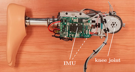
FIGURE 4. Research prototype of a leg prosthesis. The IMU is currently centralized on the visible PCB. Referring to Figure 2, moving the IMU to the bottom-right of the same PCB (indicated with a dashed line) already suggests significant shock reduction: a decent benefit for a minor cost.
The resulting shock is indicated in Figure 3, with the CoPc of the torso marked (). Most notable is that also this case illustrates that only a small portion of the shock has propagated to the torso, which is the outcome for having at least two bodies in the chain that are (nearly) perpendicular to each other: in this case Skippy’s foot and leg. In particular, the torso’s RoPc was calculated to be as large as
The resulting location of the CoPc itself however is not practical one, for the reason that it falls outside the physical body and that it is in the magnetic field and heat stream of the main motor. Nevertheless, due to the overall low shock experienced by the torso, this is not an issue. Two feasible candidate mounting locations (see I and II)5 were found in the vicinity of this point, which receive less than 2% of the applied shock. Reruns of the analysis for several other extreme landing conditions (e.g., a somersault) did not lead to a significant change of the experienced shock by the candidate mounting locations of the IMU.
4.3 Quadruped
The final case study is that of a simplified quadruped. The front and hind legs of the planar model have been merged, so that it consists of only two 2R legs and a torso: five bodies in total. Again, all bodies are modeled as slender beams with a uniform mass distribution. The leg segments all have the same length and the upper legs have quadruple the mass of the lower leg. The torso has double the mass of the legs together (
The analyzed impact scenario is that of bounding in place (Raibert, 1986; Orsolino et al., 2017), as it is known to heavily subject the robot to impacts with the ground. The study focusses on the effect of approaching a singular configuration with the impacting leg, and moreover differs from the one in Section 4.1 mainly in that the system now features a heavier torso that is horizontal instead of vertical. The inclusion of the front leg (the leg not being impacted) in the model has been done for sake of completeness, but it does not significantly influence shock propagation in the rest of the robot, as explained and observed in Sections 3.4 and 4.1.
The results of applying a vertical impact to the hind leg are shown in Figure 5 for leg segment angles ranging from 0° (singular) to 30° with respect to the vertical, and a fixed 15° rotation of the torso with respect to the horizontal.
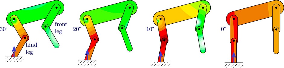
FIGURE 5. Typical shock scenarios of a quadruped during a bounding gait for different leg segment angles, as indicated with respect to the vertical. One could consider programming joint angle limits based on desired maximum shock on the torso (avoiding the 10 and 0° cases). For cases similar to the 10° case, where shock is significantly lower on one side of the torso, it could be considered to mount an IMU on both the front- and backside.
Motion controllers for quadrupedal gait generation usually enforce a desired foot position and they are not usually concerned with explicitly defining the desired leg angles at impact (Orsolino et al., 2017). These, however, have a significant influence on the shock propagation, which could affect the locomotion performance as a whole. The main body of interest for this case is the torso, because it typically houses all the sensitive components in a quadruped robot. Just like in Figures 2,4 it can be observed that the torso is relatively free of shock, but this changes as the legs approach a singular configuration, as can be seen in the 10° and 0° case. One could utilize these results to decide on maximum permissible joint limits for leg extension, to limit the shock that is being propagated to certain areas in the torso, possibly as function of the strike angle, or directly as function of the shock (in a certain location) on the torso.
In addition, as the quadruped is landing on its hind legs like depicted in Figure 5, it can be observed that the CoPc is moving toward the front (i.e., the right side of the figure) as the robot lands with more extended legs. This is best observable in the 10° case, where the shock in the front side is more than a factor of two lower than in the back side. Naturally, this pattern will be mirrored when the robot lands on its front legs. For this reason, it could be of interest to mount two IMUs in the torso: one on each side. Their readings could then be selected, or appropriately weighted through data fusion techniques, according to the amount of shock they receive, the one receiving less shock being more reliable than the other. This could potentially lead to significant improvements in inertial navigation.
5 Discussion
As showcased by the case studies, the presented methods allows to draw useful conclusions for the design of legged robots for the purpose of improving robustness against intended impacts. When the proposed design study is coupled with the synthesis of locomotion, the proposed approach can also lead to critical conclusions such as the optimal location for the placement of shock-sensitive sensors such as IMUs, Lidars and cameras.
In many cases, the behavior of shock propagation can be reasonably well predicted from the single body case and its algebraic equations. For example, by combining the small effect of bodies further down the chain with the usability of Eq. 1 for bodies at the end of the chain, it is implied that the torso of humanoids (or the main slender body of another type of robot) are well described by Eq. 1, and that their sensitive equipment is generally best placed at some point above the CoM, but below the top.
Nevertheless, case-by-case studies allow for a verification and quantification of the actual shock mitigation. An example of such a quantification is the particular case study of Skippy, where it was found that the maximum magnitude of shock in the torso did not exceed 6% from the applied one. This also illustrated that—for the purpose of placement of shock sensitive components—the exact location of the CoPc is not very relevant if the RoPc is very high. By using the CoPc in combination with the newly introduced RoPc, shock can be well described and visualized, which should further aid in the understanding of shock propagation.
The case studies furthermore provide a strong argument in favor of equipping running and jumping robots with joint that aims at keeping two bodies approximately perpendicular to each other, such as an ankle joint. In reality, the difference between shock propagation with and without the perpendicular joint is likely slightly smaller than showcased by the studies, due to the relatively stiff springs that are commonly found in an ankle prosthesis or robot joint that are not captured by the impulsive dynamics equations. To further reduce shock propagation, it can be considered to move some body mass to the other side of their joints. However, a mechanism that has been designed to completely eliminate shock propagation will likely not be fruitful due to the cost of the impractical design criteria of moving significant mass to exposed sides of joints while requiring a specific joint angle.
The proposed method is fast and requires relatively few prior knowledge about the system. However, it is based on impulsive rigid-body dynamics, which assumes bodies to be infinitely stiff and joints to have zero stiffness. In practice, bodies have a finite stiffness, and so have joints if they are actuated with stiff series elastic elements. This could lead to significantly different results if the robot is too flexible, i.e., to excitation of vibration modes with peak accelerations not necessarily proportional to those of the calculated shock. This also implies that the method is more targeted to studies that aim to obtain an approximation of shock propagation, rather than to studies that aim to be exact, such as required for the aforementioned target of completely eliminating shock propagation. As an alternative approach, FEMs can be utilized for shock analysis, which are designed to capture the influence of finite stiffness. However, the disadvantage of these methods is that they require more information, i.e., the precise stiffness of all body parts and joints, which is typically not at hand in initial stages of the design. In contrast, the presented method relies only on the existence of a rigid-body model of the system. In addition, FEM analyses are significantly more computationally expensive. Recommended possible future studies could focus on comparing impulsive rigid-body dynamics with a FEM study and reality. Nevertheless, also here the results will depend significantly on the design of the robot itself: the presented method will be more accurate for robots that are built from stiff carbon fiber tubes and soft series elastic actuators or unactuated joints.
Improving a robot’s physical robustness against mechanical impacts is not always on the horizon when initiating a robot design, yet many real robots keep failing due to incurred physical damage or malfunctioning sensors. The authors hope to inspire and promote robot designers to take shock analyses into design considerations, especially through the availability of the presented methods and analyses in this manuscript.
6 Conclusion
This manuscript has addressed the calculation and analysis of shock propagation in rigid body systems, and on how this can be used to improve a robot design and its control regarding robustness against mechanical shock. In a planar rigid body, shock can comprehensibly be expressed by the CoPc, the point which features no translational shock, and by the proposed RoPc, a radius that indicates the rate at which shock from the CoPc grows. A 3-step method is presented to calculate these variables of all bodies in a multi-rigid-body system. In contrast to FEM analyses, the method relies only on the existence of a rigid-body model of the system, and does not require full knowledge of bodies’ finite stiffness, which makes it well applicable for early stages of the design. In addition, various case studies are presented to showcase the usefulness of a shock analysis that can be done with these variables. Applications include placement of shock-sensitive components like IMUs and cameras. Whereas shock propagation is generally a function of the impact condition, typical use cases reveal that certain sides of bodies are generally less sensitive to shock than others. Shock analysis can also be applied to mechanical and controller design improvements and optimizations, as it is shown that inclusion of additional bodies (e.g., foot and ankle) and attaining desired joint configurations (i.e., proportionality) can substantially reduce shock propagation. Complementary, configurations that propagate too much shock can be avoided, for instance by setting kinematic joint limits.
Data Availability Statement
The research materials supporting this publication can be accessed by contacting the corresponding author.
Author Contributions
JD has contributed to most of the scientific contribution, including theoretical formalism, analytic calculations and numerical simulations, and took the lead in writing the manuscript. RO provided theoretical and technical support for the writing of the manuscript. Part of this project has been supported by the RAIN Hub, which is funded by the Industrial Strategy Challenge Fund, part of UK government's modern Industrial Strategy. The fund is delivered by UK Research and Innovation and managed by EPSRC [EP/R026084/1].
Conflict of Interest
The authors declare that the research was conducted in the absence of any commercial or financial relationships that could be construed as a potential conflict of interest.
Footnotes
1 This follows directly from Chasles’ theorem, which states that the most general rigid body displacement is described by a translation along a line—the screw axis—in combination with a rotation about an axis parallel to that line.
2 In this manuscript, shock is expressed as an instantaneous change of velocity, rather than a peak acceleration, hence the notation
3The solution in 3D is expressed by an axis instead of center of percussion, where shock is minimum, but not necessarily zero.
4 Note that this angle should not be confused with the angle of attack and is not representing that of the ground reaction force; it can typically be steeper before the robot starts slipping. For all the cases depicted in Figure 2, the vertical component of the ground reaction impulse was found to be greater than its horizontal component, and the leg was found not to slip assuming a friction coefficient of 1 (i.e., a 90° aperture angle of the friction cone). In practice and simulations employing continuous contact models, where the contact between the foot and ground has finite stiffness, the result of the strike angle falling outside the friction cone could instead be a microslip that is hardly noticeable on the macrodynamics of the robot.
5 In the real design, both solutions have been implemented, for each have their own advantages. Whereas (I) is closer to the calculated CoPc and easier to reach, (II) is further away from the motor and furthermore allows the IMU to be rotated by 45° about the sagittal axis. This effectively increases its saturation limit for vertical acceleration by up to a factor of
References
Agility Robotics (2020). Robots. Available at: https://www.agilityrobotics. (Accessed October 29 2020). [Dataset]
Alba, M., Prada, J. C. G., Meneses, J., and Rubio, H. (2010). Center of percussion and gait design of biped robots. Mech. Mach. Theor. 45, 1681–1693. doi:10.1016/j.mechmachtheory.2010.06.008
Battaglia, M., Blanchet, L., Kheddar, A., Kajita, S., and Yokoi, K. (2009). Combining haptic sensing with safe interaction. In IEEE/RSJ International Conference on Intelligent Robots and Systems, St. Louis, USA, October 2009 (IEEE), 231–236.
Bledt, G., Powell, M. J., Katz, B., Carlo, J. D., Wensing, P. M., and Kim, S. (2018). “MIT cheetah 3: design and control of a robust, dynamic quadruped robot,” in IEEE/RSJ international conference on intelligent robots and systems (IROS), Madrid, Spain, October 2018, 2245–2252.
Boston Dynamics (2020). Spot, Available at: https://www.bostondynamics.com/spot (Accessed October 27 2020). [Dataset]
Cross, R. (2004). Center of percussion of hand-held implements. Am. J. Phys. 72, 622–630. doi:10.1119/1.1634965
Driessen, J. J. M. (2019). Design of high-performance legged robots–a case Study on a Hopping and balancing robot. PhD thesis, Genoa, Italy: Università degli studi di Genova.
Ficken, G. W. J. (1976). Center of percussion demonstration. Am. J. Phys. 44, 789. doi:10.1119/1.10319
Fujiwara, K., Kanehiro, F., Kajita, S., and Hirukawa, H. (2004). “Safe knee landing of a human-size humanoid robot while falling forward,” in IEEE/RSJ International Conference on Intelligent Robots and Systems (IROS), Sendai, Japan, September 28–October 2, 2004, 1, 503–508. doi:10.1109/IROS.2004.1389402
Heidenfelder, J., Sterzing, T., Bullmann, M., and Milani, T. L. (2008). Heel strike angle and foot angular velocity in the sagittal plane during running in different shoe conditions. J. Foot Ankle Res. 1, O16. doi:10.1186/1757-1146-1-s1-o16
Hidaka, Y., Tsujita, T., and Abiko, S. (2020). “Drop impact analysis and shock absorbing motion of a life-sized one-legged robot with soft outer shells and a flexible joint,” in IEEE/ASME international conference on advanced intelligent Mechatronics (AIM), Boston, MA, July 2020, (IEEE), 928–933.
Hobbelen, D. G. E., and Wisse, M. (2007). A disturbance rejection measure for limit cycle walkers: the gait sensitivity norm. IEEE Trans. Rob. 23, 1213–1224. doi:10.1109/TRO.2007.904908
Hutter, M., Gehring, C., Jud, D., Lauber, A., Bellicoso, C. D., Tsounis, V., et al. (2016). “ANYmal – a highly mobile and dynamic quadrupedal robot,”in IEEE/RSJ international conference on intelligent robots and systems (IROS), Daejeon, Korea, October 2016, 38–44. doi:10.3929/ethz-a-010782581
Kenneally, G., De, A., and Koditschek, D. E. (2016). Design principles for a family of direct-drive legged robots. IEEE Rob. Autom. Lett. 1, 900–907. doi:10.1109/LRA.2016.2528294
Kim, D., Di Carlo, J., Katz, B., Bledt, G., and Kim, S. (2019). Highly dynamic quadruped locomotion via whole-body impulse control and model predictive control. Available at: https://arxiv.org/abs/1909.06586 (Accessed December 10, 2020).
Kovač, M., Schlegel, M., Zufferey, J. C., and Floreano, D. (2009). “A miniature jumping robot with self-recovery capabilities,” in IEEE/RSJ international conference on intelligent robots and systems. (IROS), St. Louis, MO, October 2009, 583–588. doi:10.1109/IROS.2009.5354005
Mummolo, C., Mangialardi, L., and Kim, J. H. (2017). Numerical estimation of balanced and falling states for constrained legged systems. J. Nonlinear Sci. 27, 1291–1323. doi:10.1007/s00332-016-9353-2
Ojeda, L. V., Zaferiou, A. M., Cain, S. M., Vitali, R. V., Davidson, S. P., Stirling, L. A., et al. (2017). Estimating stair running performance using inertial sensors. Sensors 17, 2647. doi:10.3390/s17112647
Orsolino, R., Semini, C., and Focchi, M. (2017). “A combined limit cycle–zero moment point based approach for omni-directional quadrupedal bounding,” in International conference on climbing and walking robots (CLAWAR), Pittsburgh, PA, August 2017. doi:10.1142/9789813231047
Pratt, G. A., and Williamson, M. M. (1995). “Series elastic actuators,” in IEEE/RSJ International Conference on Intelligent Robots and Systems (IROS), Pittsburgh, PA, August 1995, 1, 399–406. doi:10.1109/IROS.1995.525827
Raychowdhury, P. N., and Boyd, J. N. (1979). Center of percussion. Am. J. Phys. 47, 1088–1089. doi:10.1119/1.11982
Sato, Y., and Ohnishi, K. (2005). “Impact force reduction for hopping robot,” in 31st annual Conference of IEEE industrial Electronics Society (IECON), Raleigh, NC, November 2005.
Schuitema, E. (2012). Reinforcement Learning on autonomous humanoid robots. PhD thesis, Delft, Netherlands: Delft University of Technology.
Semini, C., Tsagarakis, N. G., Guglielmino, E., Focchi, M., Cannella, F., and Caldwell, D. G. (2011). Design of HyQ–a hydraulically and electrically actuated quadruped robot. Proc. IME J. Syst. Contr. Eng. 225, 831–849. doi:10.1177/0959651811402275
Singh, B. R. P., and Featherstone, R. (2020). Mechanical shock propagation reduction in robot legs. IEEE Rob. Autom. Lett. 5, 1183–1190. doi:10.1109/LRA.2020.2966395
Unitree (2020). Laikago. http://www.unitree.cc/ (Accessed December 10, 2020).
Vectornav (2009). VN-100 IMU/AHRS. Available at: https://www.vectornav.com/products/vn-100 Accessed February 21 2020).
Wieber, P.-B., Tedrake, R., and Kuindersma, S. (2016). Modeling and control of legged robots. Cham, Switzerland: Springer International Publishing, 1203–1234. doi:10.1007/978-3-319-32552-1_48
Yim, J. K., and Fearing, R. S. (2018). “Precision jumping limits from flight-phase control in salto-1P,” in IEEE/RSJ international conference on intelligent robots and systems (IROS). Madrid, Spain, October 2018, 2229–2236.
Keywords: legged robots, mechanical design, multibody dynamics, impulse dynamics, robustness, shock propagation, center of percussion
Citation: Driessen JJM and Orsolino R (2021) Improving Robustness of Legged Robots Against Mechanical Shock Using Impulsive Dynamics. Front. Mech. Eng. 6:601922. doi: 10.3389/fmech.2020.601922
Received: 02 September 2020; Accepted: 12 November 2020;
Published: 13 January 2021.
Edited by:
Marco Ceccarelli, University of Rome Tor Vergata, ItalyReviewed by:
Radu Iacob Cotetiu, Technical University of Cluj-Napoca, RomaniaGuiyang Xin, University of Edinburgh, United Kingdom
Copyright © 2021 Driessen and Orsolino. This is an open-access article distributed under the terms of the Creative Commons Attribution License (CC BY). The use, distribution or reproduction in other forums is permitted, provided the original author(s) and the copyright owner(s) are credited and that the original publication in this journal is cited, in accordance with accepted academic practice. No use, distribution or reproduction is permitted which does not comply with these terms.
*Correspondence: Josephus J. M. Driessen, am9zZXBodXMuZHJpZXNzZW5AaWl0Lml0