 Peng Zhang
 Pai Wang
- Department of Mechanical Engineering, University of Utah, Salt Lake City, UT, United States
Rolling waves have unconventional circular polarizations enabled by the equal-speed propagation of longitudinal and transverse waves in elastic solids. They can transport non-paraxial intrinsic (i.e. spin) mechanical angular momentum in the media. In this work, we analyze the rolling wave reflections and their effects on the non-paraxial spins in a cubic elastic half-space with an elastically supported boundary. Reflected waves from both normal and general oblique incidences are investigated. We show that, by adjusting the stiffness of the elastic boundary, we can precisely control the spin properties of the reflected waves, paving the way towards a broad category of spin manipulation techniques for bulk elastic waves.
1 Introduction
Recent advances in mechanical and acoustic metamaterials have made it possible to manipulate the general intrinsic spin angular momentum (Holanda et al., 2018; Zhu et al., 2018; An et al., 2020; Burns et al., 2020; Rückriegel et al., 2020; Shi and Yang, 2020) carried by elastic waves in the bulk (Long et al., 2018; Wang et al., 2018; Shi et al., 2019; Toftul et al., 2019; Long et al., 2020). Our previous work (Zhang et al., 2020) demonstrated that, when longitudinal and transverse elastic waves propagate at the same speed, rolling waves may emerge, carrying a spin that is orthogonal to, and in general not parallel to, the wave vector. This is only possible in anisotropic materials that satisfies certain equal-wave-speed criteria (Zhang et al., 2020). As the simplest anisotropic material characterized by only three independent elastic constants, cubic materials have been investigated in many studies (Stoneley, 1955; Borcherds, 1973). Thomas (1966) analyzed the longitudinal wave velocity at different directions using orientation components, and Mielnicki (1972) studied both longitudinal and transverse waves using approximation method. The bounds of elastic wave speeds (Zuo and Hjelmstad, 1997), surface wave polarizations (Chadwick and Wilson, 1992), and supersonic surface waves (Every, 2015) have all been the topics of an active line of research. Benefited from the fast development in additive manufacturing technology, cubic symmetric metamaterials can now provide us with a broader range of possible elastic constants (Favre et al., 2018; Tancogne-Dejean and Mohr, 2018; Lohmuller et al., 2019) even to the higher-order elasticity effects, such as the compression torsion metamaterial (Frenzel et al., 2017; Wang and Liu, 2020), hyper-stress tensor with second-gradient elasticity (Weeger, 2021), and chiral-micropolar metamaterials (Chen et al., 2021).
Although the stable propagation of rolling waves with non-paraxial spins have been demonstrated (Zhang et al., 2020), effects of boundary reflections on the wave spin angular momenta have yet to be investigated. The elastic wave reflection process is often both rich in physics and useful in applications (Schoenberg, 1980; Bedford and Drumheller, 1994; Vavrycuk and Psencík, 1998; Lee et al., 2017; Chen et al., 2019). However, studies on reflections from elastically supported boundaries of cubic materials are lacking. This further motivates us to analyze the reflection of rolling waves in a cubic material incident either normally or obliquely at such boundaries. The present work fills the gap in understanding and predicting rolling reflections and offers a new technique to manipulate the spin of elastic bulk waves.
In this paper, we first review the general governing equations for plane waves in an anisotropic medium. Next, the equal-wave-speed criteria in cubic materials are derived. Furthermore, we provide a general formulation for the spin angular momentum of bulk elastic waves. Lastly, the normal and oblique incident rolling waves are analyzed with different boundary conditions, where both spin-preserving and spin-flipping phenomena may emerge.
2 Plane Waves in Anisotropic Medium
With consideration of long-wavelength limit (i.e. quasi-static limit) only, we focus on the plane wave with wavelength much larger than any micro-structure size, which implies the dispersive behavior from geometry is negligible. The general bulk elastic wave equation without body force is,
where σ is the stress tensor and u is the displacement vector.
The general solution of plane waves is
where u0 denotes wave amplitude, and k the wave vector. We consider a plane wave propagating along an arbitrary direction specified by the unit vector,
where l1, l2, l3 are direction cosines, and e1, e2, e3 are the standard orthonormal basis vectors of Cartesian coordinates. Then, we have
where k is the wavenumber.
The time derivative of eq. 2 gives us,
With the definition of a matrix L,
We have the spatial derivative in Voigt notation (Carcione, 2007),
Combining the above equations, we arrive at
where
is the Kelvin-Christoffel matrix.
Here, we consider the phase velocity v and its amplitude, wave speed v given as,
Then, we obtain the governing equation for bulk elastic wave speeds in a general anisotropic material,
The expressions of elements in Γ are given below as,
where Cij are components of the stiffness matrix in Voigt notation (Carcione, 2007).
3 Constitutive Relation of Cubic Materials
Next, we focus our discussions on cubic materials characterized by the cubic crystallographic point groups. As illustrated in Figure 1, the symmetry conditions include four axes of three-fold rotational symmetry that can be identified with the body diagonals of a cubic unit cell (Bückmann et al., 2014; Dirrenberger et al., 2013; Authier, 2003). Rather counter-intuitively, this symmetry requirement does not include any axis of four-fold (90 degree) rotational symmetry (Ashcroft and Mermin, 1976, p. 121). The stiffness matrix of cubic material is given as (Authier, 2003; Norris, 2006; Zhang et al., 2020),
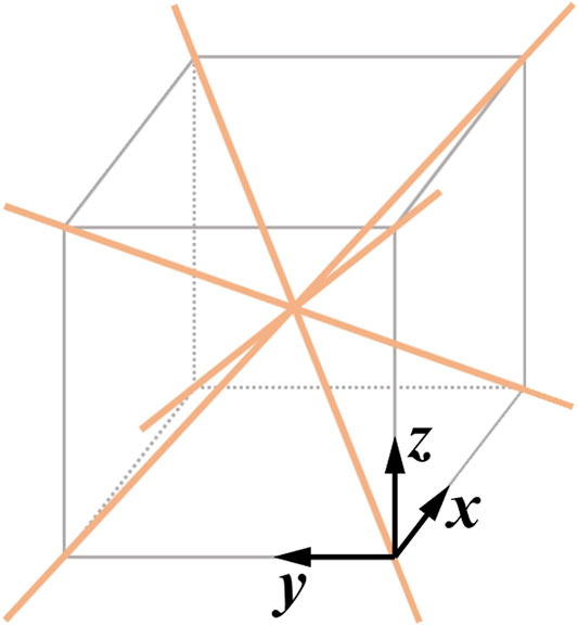
FIGURE 1. The symmetry requirement for cubic materials: Body diagonals (orange solid lines) of a cubic unit cell serve as the four axes of three-fold rotational symmetry. They are the sufficient and necessary conditions for the cubic crystallographic point groups. On the contrary to some common misconceptions, cubic materials do not need to have any four-fold rotational symmetry.
For waves propagating along the z-direction, the direction cosines are
Then, the Kelvin-Christoffel matrix components become,
Therefore, the governing eq. 11 becomes,
We note that u3 represents the longitudinal wave, while u1 and u2 represent the transverse waves. Therefore, from eq. 16, we obtain the longitudinal and transverse wave speeds as,
Thus, for waves traveling in the z-direction of a cubic material, in order to have a rolling wave with non-praxial spin polarization (Zhang et al., 2020), we need the equal-speed criterion:
By symmetry, for the waves propagating in x− or y−direction, the equal-speed criterion is exactly the same as eq. 18.
4 Intrinsic Spin Angular Momentum of Bulk Elastic Waves
To calculate the spin density of the bulk elastic waves, we consider the displacement field of a general plane wave
Importantly, here m, n and l are complex-valued, so that they contain the information not only about amplitudes but also about the relative phase differences among displacement components of the traveling wave. The spin angular momentum density, as a real-valued vector, can be calculated as (Berry, 2009; Long et al., 2018; Burns et al., 2020):
where (⋅)* denotes complex conjugation, and the spin-1 operator is a third-order tensor defined as
Hence, the spin density for a general traveling wave is
We note that the above formulation makes physical sense only if all displacement components propagate at the same wave speed. Particularly for cubic materials, the equal-speed criterion eq. 18 needs to be true. In this case, we can have stable propagation of spins pointing at any direction by adjusting the complex amplitudes m, n and l. This can be realized by simply changing the relative phase differences. Hence, the direction of the spin vector s can be completely independent from the direction of the wave vector k.
5 Normal Incidence and Reflection
We now investigate normal reflections of a rolling wave at a general elastic boundary. This serves as an example non-paraxial spin manipulation. Considering a rolling wave along the z-direction normally incident on a flat surface, we have the instantaneous wave displacement fields at time t = 0 as
where the superscripts, I and R, denote the incident and reflected waves, respectively.
For the displacement with small amplitude, the linear strain terms are dominant. In this case, by neglecting higher-order strain terms, the strains can be calculated from displacements by
where the comma “,″ in subscripts denotes the derivative operation.
The reflection occurs at z = 0. So we have eikz = e−ikz = 1, and the strain vector in Voigt notation becomes
The cubic constitutive relations are
It is easy to compute the stress components for incident and reflection waves, respectively:
For a elastically supported cubic half-space, the boundary conditions are
where (Kx, Ky, Kz) are components of the distributed stiffness per unit area (Zhang et al., 2017) representing a general elastic foundation supporting the solid surface, and the total stress and displacement are
Substituting the displacement and stress components into elastic boundary conditions, we get
Solving the above system of equations, we obtain
Because of the equal-speed requirement of rolling wave (C11 = C44), the amplitude of reflection wave becomes,
with the generalized amplitude ratio of normal reflection given as
We can also write in the form of a reflection matrix (Zoeppritz, 1919; Ursin and Tjäland, 1996):
with the reflection matrix
Here, the phase angle ϕ of Rj corresponds to the phase change during the reflection, and it dependents on the boundary-bulk stiffness ratio Kj/C11 and the wave number k, as shown in Figure 2. Therefore, by adjusting the elastic stiffness at the boundary, one can manipulate the spin of the reflected waves.
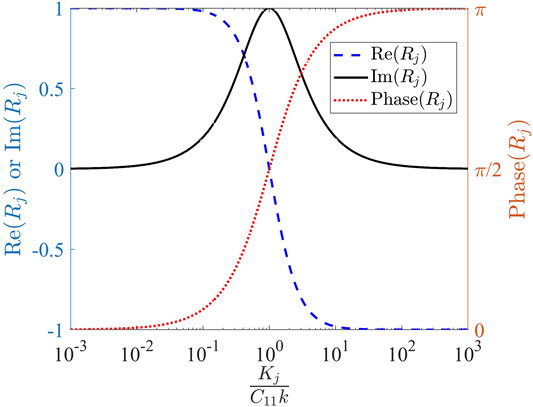
FIGURE 2. The complex-valued amplitude ratio of normal reflection, Rj, is determined by the boundary-bulk stiffness ratio, Kj/C11, and wave number k.
Although all properties of both the bulk and the reflection surface are assumed to be independent of the incidence wave frequency, here the reflection phase change can be frequency-dependent, as the angular wave number k appears in the ratio. The emergence of frequency dependency can be intuitively explained by the role of wavelength during reflection. We note from eq. 25 that k first appears in the strain calculations since, for a given wave displacement amplitude, the strains in the propagation direction, ɛzj, are actually inversely proportional to the wavelength: Longer wavelength gives rise to a smaller strain and vice versa. Consequently, the stresses, σzj, and the force acting on the boundary springs are wavelength-dependent as well. If the boundary is supported by an elastic foundation with finite stiffness per area, Kj, we have the following: At the low-frequency and long-wavelength limit, the force per area acting on the boundary, |σzj|∝ C11k → 0. So, the boundary hardly moves, and the incidence wave effectively “sees” a rigid surface; At the high-frequency and short-wavelength limit, the force per area acting on the boundary, |σzj|∝ C11k → ∞. So, the boundary moves a lot, and the incidence wave effectively “sees” a free surface.
Next, we consider some special cases and focus on the in-xz-plane rolling waves with nI = nR = 0. We note that the elastic boundary condition degenerates into traction-free boundary condition (Neumann type) when the boundary stiffness Kj → 0. Then, the amplitudes of reflected wave become
Similarly, the elastic boundary condition degenerates into the fixed rigid boundary condition (Dirichlet type) when the stiffness Kj → ∞. Then, the amplitudes of reflected wave become
In both cases above, by the definition of spin given in eq. 22, we can conclude sR = sI, as shown in Figures 3B,C. So, the spin is unaffected by the reflection process.
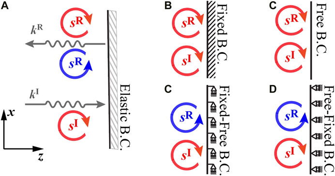
FIGURE 3. (A) Rolling wave reflections with normal incidence at a general elastic boundary. In all sub-plots, the incidence wave carries a spin angular momentum,
In addition, for the fixed-free hybrid boundary (Kx → ∞ and Kz → 0, Figure 3D), we have
Similarly, for the free-fixed hybrid boundary (Kx → 0 and Kz → ∞, Figure 3E), we have
Thus, both hybrid boundaries will flip the spin for any incident rolling wave.
Summarizing different cases for the normal incidence, we note that, for Kx → 0 and Kz → 0, the boundary becomes traction-free (Neumann type) and we have
Figure 3 illustrates the results using the example of an incident rolling wave carrying a non-paraxial spin of
6 The Oblique Incidence and Reflection at 45 degree
Next we investigate the scenario in which the boundary plane is oblique to the incident rolling wave at the 45° angle. We focus on the incident rolling wave propagating towards the positive z−direction,
As shown in Figure 4A, the incidence angle here is αI = 45°. Importantly, we note that, due to material anisotropy, the reflection angle(s) will not necessarily be equal to the incidence angle. In fact, a single incidence wave, in general, may result in multiple reflected waves towards different directions (Achenbach, 2012; Graff, 2012). Hence, the reflection angle(s) need to be determined by a detailed analysis on boundary conditions and material properties. In this case, we can write the reflection wave as a general form in xz-plane,
where θ is the angle of wave vector with respect to the x-axis. It follows that the reflection angle can be expressed as αR = θ + 45°, θ ∈ (−45°, + 45°).
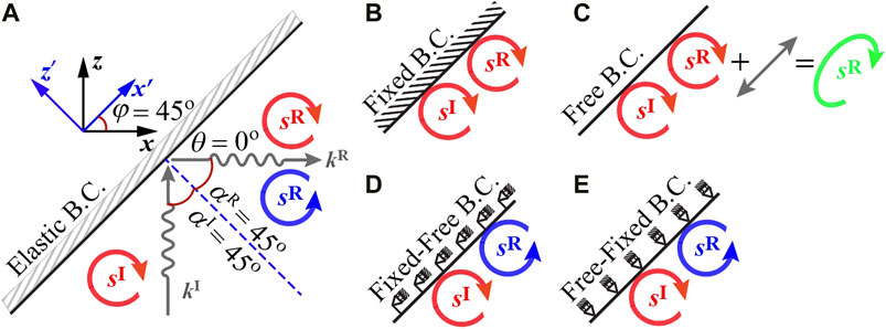
FIGURE 4. (A) Illustration of rolling wave reflections at 45° incidence. In all sub-plots, the incidence wave carries a spin angular momentum,
Next, we look into the general conditions for rolling waves propagating in the xz-plane. The normalized wave vector, as given in eq. 3, is now characterized by cosine directions l2 = 0 and
Therefore, the governing eq. 11 becomes,
Combining with the equal speed criterion in eq. 18, i.e., C11 = C44, we obtain
This shows that the in-plane waves (u1, u3) are in general coupled together, and the out-of-plane wave u2 is decoupled from the two in-plane polarizations.
For non-trivial solution to exist for in-plane wave velocities in eq. 49, the determinant must vanish. This leads to the following
This is a quadratic polynomial with respect to v2. It has the discriminant as
For any linear material to be statically stable, it needs a positive strain energy function, and hence a positive-definite stiffness matrix (Ting, 1996), which leads to the following conditions:
Then, in order to determine the reflection angle(s) in this case, we apply Snell’s law for reflection
Here, the incidence angle is αI = 45°. Combining it with ωI = ωR and
with the cosine directions,
Further simplification gives us,
For θ ∈ (−45°, + 45°) with the positive-definite conditions of eq. 52, the only solution to above equation is
which implies αR = 45°. Therefore, there can be one reflection wave vector only, and the reflected wave will propagate along x-direction at the speed vR = vI. Hence, we can rewrite the reflection wave as,
For brevity, denoting the wave number as kI = kR = k, we obtain
The corresponding strain wave amplitudes are
And the stress wave amplitudes are
To analyze the normal and transverse elastic boundary condition, we introduce a local coordinate system x′ = Ψx specified by the transformation matrix,
where the φ = 45° as shown in Figure 4.
The general elastic boundary conditions in the local coordinate system are
where (Kx′, Ky′, Kz′) are components of distributed stiffness per unit area, and
are components of total stress and total displacement on the boundary surface.
We next perform coordinate transforms using
In the local coordinates, x′, we obtain
Similarly, the local stress and displacement of reflection wave are,
Substituting the stress and displacement components eqs 67 –eqs 70 into the boundary conditions eqs 64,65, we obtain
Then, we can solve the system of eqs 71–73 for the complex-valued amplitude components of the reflected wave:
where
We can also write in the form of a reflection matrix (Zoeppritz, 1919; Ursin and Tjäland, 1996).
where
with denominator
We also note that the term Rnn for the out-of-xz-plane wave is independent and very similar to the normal incidence scenario, as shown in eqs 38,40 and Figure 2. All other terms in eq. 79 are illustrated in Figure 5 to show how they change with the wave number, k, and the boundary stiffness ratio, Kz′/Kx′. We observe in Figure 5B that both Rml and Rlm shows a phase jump of 180°. This is because of two reasons: 1) The small wave number k = 0.001 leads to the fact that both Rml and Rlm are almost purely imaginary; and 2) At the boundary stiffness ratio of Kz′/Kx′ = 3, values transition from a negative imaginary number to a positive imaginary number. This results in the 180° phase jump.
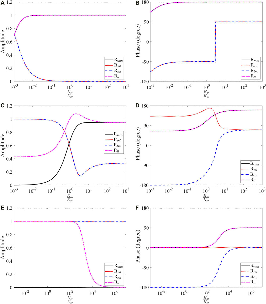
FIGURE 5. The amplitude and phase of reflection matrix elements under different wave numbers k at Cr = C12/C11 = 0. (A,B) Amplitude and phase at k = 0.001, (C,D) Amplitude and phase at k = 1, (E,F) Amplitude and phase at k = 1,000.
Clearly, the out-of-xz-plane wave nR only depends on nI:
The four extreme cases for in-xz-plane wave polarizations are:
Case I (Figure 4B), Kx′ → ∞, Kz′ → ∞:
Case II (Figure 4C), Kx′ → 0, Kz′ → 0:
with Cr = C12/C11. Here, the second term in lR is associated with lI, and mR = lI. So, this term does not have any contribution to the circularly rolling polarization, and it gives rise to an additional linearly polarized wave. Consequently, the spin is still exactly preserved, but the overall reflected wave has a elliptically rolling polarization.
Case III (Figure 4D), Kx′ → ∞, Kz′ → 0:
Case IV (Figure 4E), Kx′ → 0, Kz′ → ∞:
As illustrated in Figure 4C, the results in eq. 83 for Case II are special and remarkable. The reflected wave from the free boundary is different from all other cases. However, the reflected spin density is indeed still the same to that of the incidence wave. The reason is that the additional term in lR does not contribute to the circularly rolling polarization. To further investigate this especially interesting case, we calculate the polarization of reflected waves with different ratios of Cr = C12/C11 and plot the result in Figure 6. Note that the ratios of Cr = −1 in Figure 6A and Cr = 1 in Figure 6E are actually extreme scenarios not attainable in statically stable materials due the positive definite conditions listed in eq. 52.
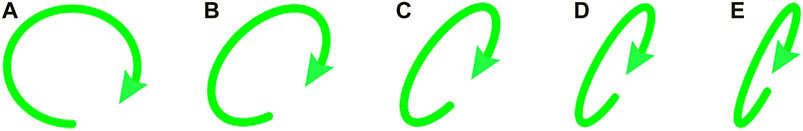
FIGURE 6. In the oblique reflection at 45°, elliptically rolling polarizations of the reflected waves from the free boundary may appear due to different material stiffness constants C11 and C12. An incident spin which is the same of that shown (A) is assumed throughout. (A) also represents the purely circularly rolling polarization for Cr = −1. (B–F) show the elliptically rolling polarizations for the cases of Cr = −0.5, Cr = 0, Cr = 0.5 and Cr = 1, respectively. Note that all polarizations are scaled for the purpose of clearly demonstrating differences in elliptical eccentricity.
7 The Oblique Incidence and Reflection at Arbitrary Angle
Next, we look into the situation with an arbitrary incidence angle. From Snell’s law eq. 53, we can obtain
where l1 = cos(θ), l3 = sin(θ). Noticed from Figure 4A that the incidence angle is identical to the rotation angle, i.e., αI = φ and then the reflection angle αR = π/2 − φ + θ. The reflection angle αR is the solution of the transcendental equation depending on the incidence angle αI and the material constant ratio Cr = C12/C11:
where “±” gives rise to two different reflected wave modes. In general, those two modes have two different reflection angles.
Next, we numerically solve eq. 87 for the reflection angle αR and illustrate the results in Figure 7. The points P1 and P2 in the plots indicate the cases of the normal incidence and the 45° incidence, respectively. Both cases have been thoroughly discussed in previous sections. The next critical point P3 is where the reflection angle αR → π/2 for Mode 1. Plugging αR = π/2 into eq. 87, we obtain:
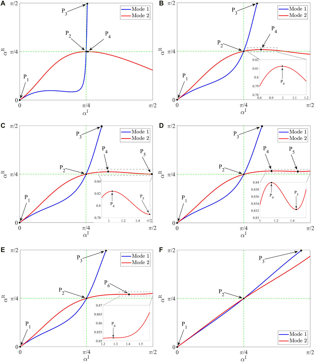
FIGURE 7. The reflection angle αR of two modes with respect to the incidence angle αI. (A) Cr = 0.9, (B) Cr = 0.1, (C) Cr = 0, (D) Cr = −0.1, (E) Cr = −0.149452, (F) Cr = −0.9.
Thus, we arrive at the analytical solution of the above equation,
with
We know that, with Δ > 0, the cubic function always has one real root and two complex conjugate roots. In this case, we can only obtain one critical angle
Here, from eq. 52 we have the constraint −1 < Cr = C12/C11 < 1. Hence, we investigate all values of Cr within this range and find the following four representative scenarios for Mode 2 of the reflected waves:
• For 0 < Cr < 1, as shown in Figures 7A,B, we have one local maximum (point P4) and no local minimum for Mode 2. The reflection angle αR will increase together with the incidence angle αI until it reaches to the maximum at point P4. Then, the anomalous trend appears, and the reflection angle αR will decrease if we further increase the incidence angle αI. Consequently, for Mode 2, we may have two different incidence angles with the same reflection angle.
• For −0.149 < Cr ≤ 0, as shown in Figures 7C,D, we have one local maximum (point P4) and one local minimum (point P5). Remarkably, as shown in the inset of Figure 7D, we may have three different incidence angles with the same reflection angle for Mode 2. Also, we note that, with the decreasing value of Cr, point P4 and point P5 move closer to each other.
• For Cr = −0.149, as shown in Figure 7E, we have no local maximum, no local minimum, but a saddle point (point P6). This saddle point P6 is the result of point P4 and point P5 merging together.
• For −1 < Cr < −0.149452 as shown in Figure 7F, we have a monotonic curve for Mode 2. The reflection angle αR always increases with the increasing incidence angle αI. And this is the normal phenomenon generally understood.
In the first two scenarios listed above, we have the anomalous trend phenomenon: The reflection angle αR does not have a monotonic relationship with the incidence angle αI. This may provide us with a new technique to control the direction of reflected waves.
Furthermore, we can take the derivative of both sides of eq. 87 with respect to the incidence angle αI and obtain the changing rate of reflection angle αR of Mode 2,
We note that this derivative of αR with respect to the αI is the root of another transcendental equation and rarely has closed-form solution. Thus, we solve it numerically and plot the results in Figure 8. The same four represented scenarios discussed above can be easily categorized here as different number of roots of eq. 91. The results shown in Figures 7, 8 are consistent with each other.
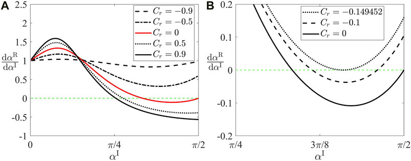
FIGURE 8. The derivative of reflection angle αR with respect to the incidence angle αI. (A) Whole range of Cr, (B) Zoom-in range of Cr with two zero roots.
8 Conclusion
Cubic materials are anisotropic elastic materials that satisfy the symmetry requirements illustrated in Figure 1, and their stiffness matrix is given by eq. 13. If the equal-speed criteria for longitudinal and transverse waves, as given in eq. 18, also holds in a cubic material, then we can have stable propagation of any spin angular momentum carried by bulk elastic waves. In this paper, we focus on rolling waves, which have a spin vector orthogonal to its wave vector, in cubic materials. We investigate the reflections of rolling waves incident either normally or obliquely at an elastically supported flat boundary. Behaviors of spin-preserving, spin-flipping, and general arbitrary phase shifts are shown by adjusting the boundary conditions. This work provides a new approach to manipulating bulk elastic wave spins. Several other key findings are summarized below:
1) For the normal incidence of rolling waves, the reflection is spin-preserving at both the fixed rigid boundary and the free boundary, while being spin-flipping at both the fixed-free and free-fixed boundaries. Most generally, we can even introduce the arbitrary phase shifts between reflection and incidence waves by adjusting the elastic boundary conditions.
2) For oblique incidence at 45°, we prove that, contrary to the general anisotropic case, there will be only 1 reflected wave with a unique reflection angle of 45°.
3) With the 45° incidence, the reflection is spin-preserving at a fixed rigid boundary, while being spin-flipping at both fixed-free and free-fixed boundaries. The free boundary is a uniquely special case here: While the reflection is still spin-preserving, depending on the cubic material constant ratio, C12/C11, it will also introduce an additional linearly polarized part. Hence, an incidence wave with circularly rolling polarization will result in a reflected wave with elliptically rolling polarization.
4) For an arbitrary incidence angle, we showed that each incidence wave will in general result in two reflected wave modes with different reflection angles. One of the mode (Mode 1 in Figure 7) exists only when the incidence angle is less than a critical value
5) We developed a new way to manipulate the elastic wave spin. Further, the present study can be extended to more general cases, i.e., arbitrary incidence angle for reflection and refraction problem, the reflection matrix properties of arbitrary incidence angle, visco-elastically supported boundary condition, or breaking the limit of statically stable materials by using metamaterials.
Data Availability Statement
The original contributions presented in the study are included in the article/Supplementary Material, further inquiries can be directed to the corresponding author.
Author Contributions
PZ is the primary contributor to this study and this manuscript. PW is the secondary contributor to this study and this manuscript.
Funding
This work was supported by start-up funds of the Dept. Mechanical Engineering at Univ. Utah.
Conflict of Interest
The authors declare that the research was conducted in the absence of any commercial or financial relationships that could be construed as a potential conflict of interest.
Publisher’s Note
All claims expressed in this article are solely those of the authors and do not necessarily represent those of their affiliated organizations, or those of the publisher, the editors and the reviewers. Any product that may be evaluated in this article, or claim that may be made by its manufacturer, is not guaranteed or endorsed by the publisher.
Acknowledgments
The support and resources from the Center for High Performance Computing at Univ. Utah are gratefully acknowledged.
References
An, K., Litvinenko, A., Kohno, R., Fuad, A., Naletov, V., Vila, L., et al. (2020). Coherent Long-Range Transfer of Angular Momentum Between Magnon Kittel Modes by Phonons. Phys. Rev. B 101, 060407. doi:10.1103/physrevb.101.060407
Ashcroft, N. W., and Mermin, N. D. (1976). Solid State Physics. New York London): Holt, Rinehart and Winston.
Authier, A. (2003). International Tables for Crystallography: Volume D: Physical Properties of Crystals. Wiley Online Library.
Bedford, A., and Drumheller, D. (1994). Elastic Wave Propagation. Amsterdam: John Wileg g Sons, 151–165.
Berry, M. V. (2009). Optical Currents. J. Opt. A: Pure Appl. Opt. 11, 094001. doi:10.1088/1464-4258/11/9/094001
Borcherds, P. H. (1973). The Scattering of Light by Elastic Waves in Cubic Crystals. Optica Acta Int. J. Opt. 20, 147–159. doi:10.1080/713818743
Bückmann, T., Schittny, R., Thiel, M., Kadic, M., Milton, G. W., and Wegener, M. (2014). On Three-Dimensional Dilational Elastic Metamaterials. New J. Phys. 16, 033032. doi:10.1088/1367-2630/16/3/033032
Burns, L., Bliokh, K. Y., Nori, F., and Dressel, J. (2020). Acoustic versus Electromagnetic Field Theory: Scalar, Vector, Spinor Representations and the Emergence of Acoustic Spin. New J. Phys. 22, 053050. doi:10.1088/1367-2630/ab7f91
Carcione, J. M. (2007). Wave fields in Real media: Wave Propagation in Anisotropic, Anelastic, Porous and Electromagnetic media. Amsterdam: Elsevier.
Chadwick, P., and Wilson, N. (1992). The Behaviour of Elastic Surface Waves Polarized in a Plane of Material Symmetry. Iii. Orthorhombic and Cubic media. Proc. R. Soc. Lond. A. 438, 225–247. doi:10.1098/rspa.1992.0104
Chen, Y., Kadic, M., and Wegener, M. (2021). Chiral Triclinic Metamaterial Crystals Supporting Isotropic Acoustical Activity and Isotropic Chiral Phonons. Proc. R. Soc. A. 477, 20200764. doi:10.1098/rspa.2020.0764
Chen, Y., Li, X., Nassar, H., Norris, A. N., Daraio, C., and Huang, G. (2019). Nonreciprocal Wave Propagation in a Continuum-Based Metamaterial with Space-Time Modulated Resonators. Phys. Rev. Appl. 11, 064052. doi:10.1103/physrevapplied.11.064052
Dirrenberger, J., Forest, S., and Jeulin, D. (2013). Effective Elastic Properties of Auxetic Microstructures: Anisotropy and Structural Applications. Int. J. Mech. Mater. Des. 9, 21–33. doi:10.1007/s10999-012-9192-8
Every, A. G. (2015). Supersonic Surface Acoustic Waves on the 001 and 110 Surfaces of Cubic Crystals. The J. Acoust. Soc. America 138, 2937–2944. doi:10.1121/1.4934557
Favre, J., Lohmuller, P., Piotrowski, B., Kenzari, S., Laheurte, P., and Meraghni, F. (2018). A Continuous Crystallographic Approach to Generate Cubic Lattices and its Effect on Relative Stiffness of Architectured Materials. Additive Manufacturing 21, 359–368. doi:10.1016/j.addma.2018.02.020
Frenzel, T., Kadic, M., and Wegener, M. (2017). Three-Dimensional Mechanical Metamaterials with a Twist. Science 358, 1072–1074. doi:10.1126/science.aao4640
Holanda, J., Maior, D. S., Azevedo, A., and Rezende, S. M. (2018). Detecting the Phonon Spin in Magnon-Phonon Conversion Experiments. Nat. Phys 14, 500–506. doi:10.1038/s41567-018-0079-y
Lee, H. J., Lee, J. R., Moon, S. H., Je, T. J., Jeon, E. C., Kim, K., et al. (2017). Off-Centered Double-Slit Metamaterial for Elastic Wave Polarization Anomaly. Sci. Rep. 7, 1–13. doi:10.1038/s41598-017-15746-2
Lohmuller, P., Favre, J., Kenzari, S., Piotrowski, B., Peltier, L., and Laheurte, P. (2019). Architectural Effect on 3d Elastic Properties and Anisotropy of Cubic Lattice Structures. Mater. Des. 182, 108059. doi:10.1016/j.matdes.2019.108059
Long, Y., Ge, H., Zhang, D., Xu, X., Ren, J., Lu, M.-H., et al. (2020). Symmetry Selective Directionality in Near-Field Acoustics. Natl. Sci. Rev. 7, 1024–1035. doi:10.1093/nsr/nwaa040
Long, Y., Ren, J., and Chen, H. (2018). Intrinsic Spin of Elastic Waves. Proc. Natl. Acad. Sci. USA 115, 9951–9955. doi:10.1073/pnas.1808534115
Mielnicki, J. (1972). Elastic Waves in {100}, {110}, and {111} Planes of Cubic Crystals. IEEE Trans. Son. Ultrason. 19, 15–17. doi:10.1109/t-su.1972.29636
Norris, A. N. (2006). Poisson's Ratio in Cubic Materials. Proc. R. Soc. A. 462, 3385–3405. doi:10.1098/rspa.2006.1726
Rückriegel, A., Streib, S., Bauer, G. E. W., and Duine, R. A. (2020). Angular Momentum Conservation and Phonon Spin in Magnetic Insulators. Phys. Rev. B 101, 104402. doi:10.1103/physrevb.101.104402
Schoenberg, M. (1980). Elastic Wave Behavior Across Linear Slip Interfaces. J. Acoust. Soc. America 68, 1516–1521. doi:10.1121/1.385077
Shi, C., Zhao, R., Long, Y., Yang, S., Wang, Y., Chen, H., et al. (2019). Observation of Acoustic Spin. Natl. Sci. Rev. 6, 707–712. doi:10.1093/nsr/nwz059
Shi, X., and Yang, J. (2020). Spin-1 Weyl Point and Surface Arc State in a Chiral Phononic Crystal. Phys. Rev. B 101, 214309. doi:10.1103/physrevb.101.214309
Stoneley, R. (1955). The Propagation of Surface Elastic Waves in a Cubic Crystal. Proc. R. Soc. Lond. A. 232, 447–458. doi:10.1098/rspa.1955.0230
Tancogne-Dejean, T., and Mohr, D. (2018). Elastically-Isotropic Elementary Cubic Lattices Composed of Tailored Hollow Beams. Extreme Mech. Lett. 22, 13–18. doi:10.1016/j.eml.2018.04.005
Thomas, T. Y. (1966). Longitudinal Waves in Cubic Crystals. Proc. Natl. Acad. Sci. 55, 1011–1014. doi:10.1073/pnas.55.5.1011
Ting, T. C. T. (1996). Positive Definiteness of Anisotropic Elastic Constants. Maths. Mech. Sol. 1, 301–314. doi:10.1177/108128659600100302
Toftul, I. D., Bliokh, K. Y., Petrov, M. I., and Nori, F. (2019). Acoustic Radiation Force and Torque on Small Particles as Measures of the Canonical Momentum and Spin Densities. Phys. Rev. Lett. 123, 183901. doi:10.1103/physrevlett.123.183901
Ursin, B., and Tjåland, E. (1996). The Information Content of the Elastic Reflection Matrix. Geophys. J. Int. 125, 214–228. doi:10.1111/j.1365-246x.1996.tb06547.x
Vavrycuk, V., and Psencík, I. (1998). Pp-Wave Reflection Coefficients in Weakly Anisotropic Elastic media. Geophysics 63, 2129–2141.
Wang, L., and Liu, H.-T. (2020). 3D Compression-Torsion Cubic Mechanical Metamaterial with Double Inclined Rods. Extreme Mech. Lett. 37, 100706. doi:10.1016/j.eml.2020.100706
Wang, S., Ma, G., and Chan, C. T. (2018). Topological Transport of Sound Mediated by Spin-Redirection Geometric Phase. Sci. Adv. 4, eaaq1475. doi:10.1126/sciadv.aaq1475
Weeger, O. (2021). Numerical Homogenization of Second Gradient, Linear Elastic Constitutive Models for Cubic 3d Beam-Lattice Metamaterials. Int. J. Sol. Structures 224, 111037. doi:10.1016/j.ijsolstr.2021.03.024
Zhang, P., Kern, C., Sun, S., Weitz, D. A., and Wang, P. (2020). Rolling Waves with Non-Paraxial Phonon Spins. arXiv preprint arXiv:2009.13014
Zhang, P., Wei, P., and Li, Y. (2017). Reflection of Longitudinal Displacement Wave at the Viscoelastically Supported Boundary of Micropolar Half-Space. Meccanica 52, 1641–1654. doi:10.1007/s11012-016-0514-z
Zhu, H., Yi, J., Li, M.-Y., Xiao, J., Zhang, L., Yang, C.-W., et al. (2018). Observation of Chiral Phonons. Science 359, 579–582. doi:10.1126/science.aar2711
Zoeppritz, K. (1919). Erdbebenwellen viii b, uber reflexion and durchgang seismischer wellen durch unstetigkeisflachen. Gottinger Nachr 1, 66–84.
Keywords: spin, elastic wave, rolling wave, cubic material, metamaterial, wave reflection, free boundary, fixed boundary
Citation: Zhang P and Wang P (2021) Boundary Reflections of Rolling Waves in Cubic Anisotropic Material. Front. Mech. Eng 7:704192. doi: 10.3389/fmech.2021.704192
Received: 01 May 2021; Accepted: 16 July 2021;
Published: 17 August 2021.
Edited by:
Chengzhi Shi, Georgia Institute of Technology, United StatesReviewed by:
Mostafa Habibi, Duy Tan University, VietnamFan Ye, University of Massachusetts Amherst, United States
Chen Shen, Rowan University, United States
Copyright © 2021 Zhang and Wang. This is an open-access article distributed under the terms of the Creative Commons Attribution License (CC BY). The use, distribution or reproduction in other forums is permitted, provided the original author(s) and the copyright owner(s) are credited and that the original publication in this journal is cited, in accordance with accepted academic practice. No use, distribution or reproduction is permitted which does not comply with these terms.
*Correspondence: Pai Wang, cGFpLndhbmdAdXRhaC5lZHU=