 J. Fan†
 J. Lemonde
 L. G. Villanueva
- Advanced NEMS Laboratory, École Polytechnique Fédérale de Lausanne (EPFL), Lausanne, Switzerland
Micro and Nano Electro Mechanical systems (M/NEMS) have a lot of potential to be used for sensing in different schemes and operation modes. We focus here on the use of coupled resonators for sensing and address the major limitation that these systems face, which stems from a compromise between dynamic range and responsivity. When the system becomes unbalanced, the responsivity drops. To solve this issue, we propose the use of piezoelectric-based stress tuning of the stiffness of the resonators in order to rebalance the system of resonators. With this approach we expect to be able to extend the dynamic range of such systems by some orders of magnitude.
Introduction
Microelectromechanical systems (MEMS) are nowadays an integral part of our society, and they are present in most consumer electronic devices, particularly within mobile phones, wearables and Internet of Things (IoT). They are essential in communications (Gong et al., 2021; Yandrapalli et al., 2021), timing elements (Perrott et al., 2013), and sensing, as for example accelerometers (Plaza et al., 2002; Park et al., 2006), gyroscopes (Tabrizian et al., 2013), fingerprint sensors (Lu et al., 2015; Jiang et al., 2017), etc. Together with their smaller counterpart, Nanoelectromechanical systems (NEMS) (Schmid et al., 2016), due to their small size, mass and stiffness, they have enormous potential to expand their use as sensors for different applications, for example in bio-sensing. Multiple research laboratories have been working on this for the past 20 years, ever since the first seminal work from IBM (Fritz et al., 2000; Arlett et al., 2011; Boisen et al., 2011; Tamayo et al., 2013). M/NEMS can be used for sensors in two main modes: Either static or dynamic detection. In the former, the deflection of the mechanical device is directly proportional to the magnitude to be measured, which can be biomolecules concentration in a solution (Mertens et al., 2008; Braun et al., 2009), different gases (Baller et al., 2000; Hierlemann et al., 2000), and forces at the tip (Binnig et al., 1986; Tosolini et al., 2010), among others.
When operating in dynamic mode, the devices are continuously moving at (or close to) their resonance frequency and, typically, one monitors the frequency to observe changes in either the stiffness or the mass of the resonator (Ramos et al., 2006; Ramos et al., 2008). Using the resonance frequency as the tracking parameter is very interesting since the noise in the measurement can be reduced significantly (Sadeghi et al., 2020). An alternative way of operating while using dynamic mode is based on the use of coupled resonators systems (Zhao et al., 2016). Coupled resonators have been known and studied for very long in classical mechanics, and only more recently in M/NEMS, both in theoretical (Lifshitz and Cross, 2003; Bromberg et al., 2006; Lifshitz et al., 2008; Kenig et al., 2012) and experimental works (Sato et al., 2006; Karabalin et al., 2009; Karabalin et al., 2011; Matheny et al., 2014). It was around 15 years ago that they were first proposed as sensors in the microscale (Spletzer et al., 2006). The main original idea behind this concept was to use the symmetry of a system composed of two perfectly identical coupled resonators, that then suddenly stop being identical when a given event happens only to one of them, e.g., molecule binding or mass landing in one of the resonators. In that case, the symmetry is broken and the eigenmodes change. If the coupling is small enough, this implies that the system transitions from a situation where the motion is equally distributed over the resonators, to a situation where modes are localized on individual resonators (mode localization, Anderson localization) (Zalalutdinov et al., 2006; Spletzer et al., 2008). This technique is very interesting because it offers an intrinsic common mode rejection (if both resonators undergo the same change, the overall system will remain symmetric) and the changes can be very significant, provided the coupling is small. This shows the main limitation of this technique: on the one hand the coupling needs to be small to provide a large change in the eigenmodes; while on the other hand it needs to be large enough that it ensures a distributed mode in the original state. This is in turn important for two reasons mainly: Fabrication uncertainties or tolerances, which will result in non-perfectly identical devices; and dynamic range, since from the moment that events start to happen to a particular resonator in the system, symmetry will be broken. Many interesting systems have been presented even with this limitation being present: Arrays of many resonators with small (Stassi et al., 2017; Stassi et al., 2019) or large coupling (Marquez et al., 2017); mass sensors (Thiruvenkatanathan et al., 2010a; Wang et al., 2018), electrometers (Thiruvenkatanathan et al., 2010b), accelerometers (Pandit et al., 2019; Wang et al., 2020; Zhang et al., 2020; Zhang et al., 2021), etc.
In order to bypass the limitation, two approaches have been suggested. One option is to stop looking into mode localization, but still looking at the eigenmodes rather than the eigenvalues as a sensing parameter. This has been routinely explored by using 3 coupled resonators, where there is a resonator that is only used to make the overall sensing procedure more stable (Zhao et al., 2015a; Zhao et al., 2015b; Zhao et al., 2016; Wang et al., 2018). The other option has been to use electrostatic softening of the resonance frequency (Schmid et al., 2016) in order to balance the difference between the two resonators (Walter et al., 2016; Rabenimanana et al., 2019).
In this paper, we present the concept of using piezoelectrically-induced tension in order to tune the resonant frequency of the individual resonators (Karabalin et al., 2012) and thus rebalance the original system. The main advantages over electrostatic tuning are the linearity of the effect and the fact that it is linearly proportional to voltage, providing both softening and stiffening depending on the sign of the applied electric field. We start by providing a succinct revision of the theory behind coupled modes. We then present the fabrication of the proposed devices followed by some simulations of the fabricated devices to compare their behavior with the theory.
Theory
Mode Coupling
The first two coupled eigenfrequencies of a pair of coupled clamped-clamped beam resonators depend not only on the coupling factor
A lumped-element model corresponding to Figure 1 can be expressed in the following way, through the equation of motion:
where
where
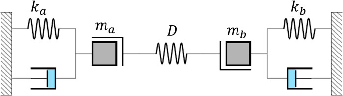
FIGURE 1. Lumped-element model of a pair of coupled resonators showing the different parameters in the system.
From Eq. 2, the eigenvalues
and the eigenvectors correspond to the coupled eigenmodes
where
In the particular case when
Importantly, there exists another value for the offset of original frequencies,
However, if
As already mentioned in the introduction, when the two individual resonators are identical and a perturbation happens in only one of them, e.g.
where
Uncoupled Eigenfrequencies and the Coupling Stiffness
When experimentally characterizing a system of two coupled resonators, the experimental data includes the coupled modes eigenfrequencies
In the case where the resonators are identical (i.e.,
However, in the general case the resonators are not identical, and then one cannot estimate the coupling using Eq. 7. In the general case, it is necessary to use Eqs 3, 4 to calculate the frequencies of the individual resonators and the coupling. This is rather important, so that we can act upon the system and bring
and the coupling by:
where we use the ratios between the first coordinate and the second coordinate of each eigenvector,
Effect of Piezoelectric Strain
As we have mentioned above, the optimal operating points once the resonators are not identical are given by
To start with, we consider a system where each resonator is a clamped-clamped beam. We know that each of these beams has indeed an infinite number of normal modes, but we will make the approximation that only the first one is excited. The frequency can be written, provided that the intrinsic stress is not very large, as (Lifshitz et al., 2008; Schmid et al., 2016):
where
In our case, as said above, we only consider the first mode of each uncoupled resonator, which gives:
To calculate the effect on the stress of the piezoelectric layer when we apply a voltage, we assume that the dimensions of the beam hold that the thickness is much smaller than the width, and the width smaller than the length:
where
The effect of the stress
where the sum extends to all the layers in the beam cross section, including: the piezoelectric layer, each layer having a built-in stress
Required Voltage to Balance Manufacturing Errors
When we have two coupled beams that are not identical but manufactured on the same wafer and with the same layers, we can partially compensate this difference with the piezoelectric voltage. Essentially:
with both frequencies being slightly different and, for the sake of simplicity, we can assume that only one of the beams (beam
where we use that the built-in stress effect in both beams is almost identical, and that the width is constant within the cross section. Thus, to balance the frequencies we must apply the following voltage:
From an experimental point of view, Eq. 16 cannot be directly used since we do not have access to the uncoupled beams frequencies. The voltage must be found experimentally by applying DC voltage on beam
Fabrication
A suggested process flow for the fabrication of the devices is shown in Figure 2. At first, 200 nm of low stress silicon nitride are deposited on a silicon wafer via low-pressure chemical vapor deposition (LPCVD) at 840°C. This first layer is there because the metal and piezoelectric layers show very large compressive stress and thus, we need to ensure that buckling does not happen. Then, the bottom contact of the electrodes is fabricated via lift-off. As depicted in Figure 2A, the lithography is defined in a bilayer of LOR 5A (400 nm) and AZ 1512 (1.1 μm) before 15 nm of aluminum nitride (AlN) and 25 nm of platinum (Pt) are sputtered at room temperature. This combination of AlN and Pt, represented in Figure 2C, gives the best conditions for the subsequent growth of the active piezoelectric layer (Howell et al., 2019). Immersion of the wafer in Microposit Remover 1165 for few tens of hours with occasional sonication sessions dissolves the photoresist and defines the bottom contact tracks (Figure 2C). The piezoelectric active layer (AlN) is then sputtered at a temperature of 300°C, targeting either 50 or 100 nm depending on the wafer, before depositing 25 nm of Pt for the top contact with the same equipment, without breaking vacuum (Figure 2D). As depicted in Figure 2E, the second mask is defined in a 1.5 μm-thick layer of AZ ECI 3007. Dry etching is then performed to pattern the top contact and the piezoelectric layer. A chlorine-based chemistry is used for both layers, accelerating the process (Figure 2F). After dicing the wafer into 1 × 1 cm2 chips, the lithography to shape the beams and for their release is done with 3 μm of AZ ECI 3027 photoresist, as shown in Figure 2G. All three layers (Pt, AlN, and SiN) are etched in the same step, with the same recipe as for the previous etching (Figure 2H). The final release of the devices, depicted in the last step of the process flow, is achieved through a short Bosch process before an isotropic etching in SF6 to suspend the devices. Figure 3 shows a scanning electron microscope picture of coupled clamped-clamped beams at the end of the fabrication, together with its thermomechanical noise measured using a laser Doppler vibrometer (LDV) from Polytec (OFV-5000), and that shows both normal modes.
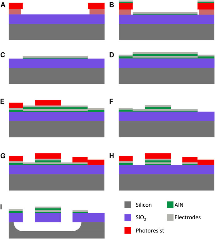
FIGURE 2. Fabrication process flow: the fabrication starts with the definition of the bottom contacts in a bilayer coating of LOR and AZ1512 (A). Then, AlN and Pt are sputtered at room temperature (B), before immersing the wafer in Remover 1165 for lift-off (C). The active layer of AlN and the Pt top electrode are subsequently sputtered (D). The second lithography mask is used to pattern the top contacts and piezoelectric layer (E,F). The final mask defines the shape of the resonators (G). An anisotropic etching of the bottom contacts is conducted (H), before the silicon nitride is etched and the devices are released in SF6 (I).
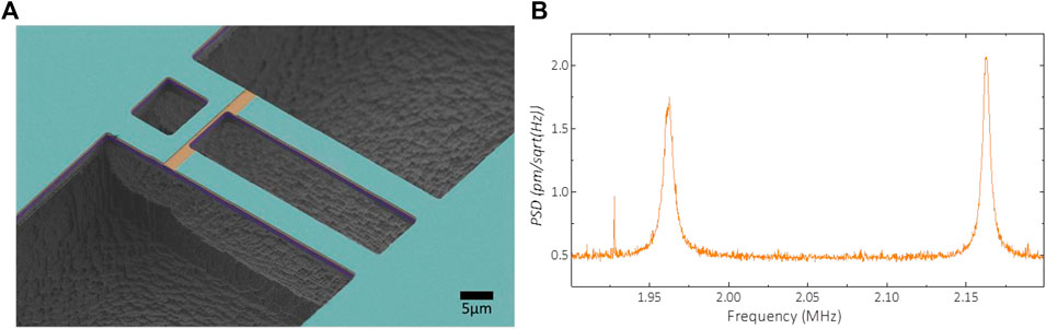
FIGURE 3. (A) Scanning electron microscope image of coupled clamped-clamped beams. The top electrode is cut to allow for a better actuation of the motion. Several designs are being considered, including changes in the dimensions and position of the coupling beam. The weakest coupling is achieved when the coupling beam is removed altogether, and the coupling is attained via the ledge that joins the anchors of both beams (B) Thermomechanical noise of the two coupled modes measured using laser Doppler vibrometry (LDV) on the structure shown on the SEM image.
Finite Element Modelling
In order to confirm the predicted behavior from our theoretical analysis, we perform Finite Element Simulations using COMSOL Multiphysics. We use a set of dimensions that are also used in the fabrication, with
The simulation results when the beams are identical and the coupling is very weak, yield
Unbalancing the Resonators’ Masses
To model a difference in the respective masses of both resonators without significantly altering the other characteristics of the resonators, we choose to slightly change the density of one of the used materials in one of the beams. Figure 4A shows the influence of an added mass on the two coupled eigenfrequencies
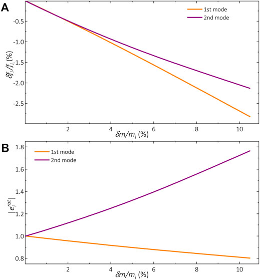
FIGURE 4. FEM results showing (A) the shift in frequencies for both eigenmodes and (B) the change in the amplitude ratios for both eigenmodes, as a function of the relative mass added to one of the individual resonators. With the particular set of parameter values that was used in this case, a 10% relative difference in the masses of the individual resonators provides a change of 2–3% in the eigenvalues; whereas a change 20% or up to 80% in the eigenmodes (this change defined as the modulus of the ratio between the coordinates of each mode,
Figure 4 exemplifies, even with a not-so-small coupling, that the effect of an asymmetry on the ratio of the modes is much larger than the effect on the frequencies. With this particular parameter values, when a 10% of relative mass difference, the frequencies change between 2 and 3%. Alternatively, the eigenmodes change either 20% (symmetric mode) or up to 80% (anti-symmetric mode).
Applying Voltage on One of the Resonators
It is also possible to study the effect of applying a voltage on one of the individual resonators and observe the effect on the eigenfrequencies and eigenvectors. To start with, we perform this simulation with the resonators being initially identical. We observe that the voltage unbalances the resonators in both ways, depending on the polarity of the voltage (Figure 5A). In Figure 5B we can also see the impact of the applied voltage on the ratio of the amplitudes in each eigenmode. The resonator on which a positive voltage is applied, resonates at greater amplitudes than the other resonator on the first coupled eigenmode; while on the second coupled eigenmode, it has a lower amplitude. Applying a negative voltage results in the opposite effect. As in the case for the addition of mass, the effect of asymmetry on the eigenmodes is indeed larger than on the eigenvalues.
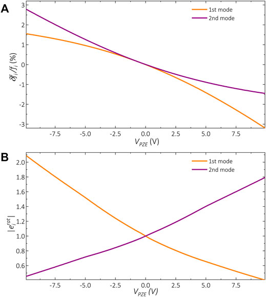
FIGURE 5. FEM results showing (A) the shift in frequencies for both eigenmodes and (B) the change in the amplitude ratios for both eigenmodes, as a function of the voltage applied to one of the individual resonators.
Voltage Required to Compensate a Given Added Mass
In order to determine which voltage is required to balance coupled resonators that are not symmetric (initially unbalanced), we perform a double parameter sweep of the original mass difference and the applied voltage. For each tested voltage, we identify the amount of mass difference that can be compensated by finding balanced amplitudes in the first coupled eigenmode, i.e., when
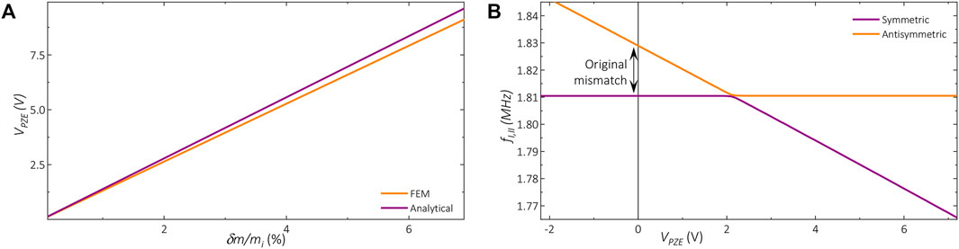
FIGURE 6. (A) Piezoelectric voltage required to be applied in one resonator (e.g., a) to balance the pair when an additional mass is distributed along the other resonator (e.g., b). Comparison is shown between FEM results and analytical estimation (
Conclusion
In this paper, we have revisited the concept of coupled resonators for sensing, and we have proposed a novel technique to bypass the main limitation of this concept, which stems from having a non-symmetrical system (for example due to a mass imbalance). Our proposed approach is based on compensating the imbalance between the couple of resonators by tuning the stress along one of the resonators using piezoelectricity, i.e., applying a DC voltage across a piezoelectric layer that is part of the resonators.
We first performed an analysis of the system, focusing on the cases where the initial system is not symmetric. We then highlighted the need to measure both the eigenfrequencies and the eigenmodes in order to estimate the individual frequencies and also the coupling. We then presented the analytical formulas that explain the piezoelectric effect, as well as finite element simulations that confirm the effect. We also presented a possible fabrication process flow that can be used to obtain the type of devices we propose, and even an example of the first generation of fabricated devices. We are currently working on a second generation of devices to experimentally test the predictions performed in this paper. With this approach, we expect to be able to extend the dynamic range of such systems by some orders of magnitude.
Data Availability Statement
The raw data supporting the conclusion of this article will be made available by the authors, without undue reservation.
Author Contributions
JF designed, fabricated, and simulated the coupled resonators. JL performed FEM simulations and developed the theoretical analysis. MK performed FEM simulations. DM fabricated and characterized the devices. LV conceived the project, and supervised the design, fabrication, simulation, and experimental work. All authors collaborated in the writing of the manuscript.
Funding
Swiss National Science Foundation grants PP00P2_144695, PP00P2_170590, 206021_177011, and IZSEZ0_186799.
Conflict of Interest
The authors declare that the research was conducted in the absence of any commercial or financial relationships that could be construed as a potential conflict of interest.
Publisher’s Note
All claims expressed in this article are solely those of the authors and do not necessarily represent those of their affiliated organizations, or those of the publisher, the editors and the reviewers. Any product that may be evaluated in this article, or claim that may be made by its manufacturer, is not guaranteed or endorsed by the publisher.
Acknowledgments
We would like to acknowledge the help and support in the fabrication of the devices from the Center for Micro and NanoTechnology (CMi) at EPFL.
References
Arlett, J. L., Myers, E. B., and Roukes, M. L. (2011). Comparative Advantages of Mechanical Biosensors. Nat. Nanotech 6 (4), 203–215. doi:10.1038/nnano.2011.44
Baller, M. K., Lang, H. P., Fritz, J., Gerber, C., Gimzewsk, J. K., Drechsler, U., et al. (2000). A Cantilever Array-Based Artificial Nose. Ultramicroscopy 82 (1-4), 1–9. doi:10.1016/s0304-3991(99)00123-0
Binnig, G., Quate, C. F., and Gerber, C. (1986). Atomic Force Microscope. Phys. Rev. Lett. 56 (9), 930–933. doi:10.1103/physrevlett.56.930
Boisen, A., Dohn, S., Keller, S. S., Schmid, S., and Tenje, M. (2011). Cantilever-like Micromechanical Sensors. Rep. Prog. Phys. 74 (3). doi:10.1088/0034-4885/74/3/036101
Braun, T., Ghatkesar, M. K., Backmann, N., Grange, W., Boulanger, P., Letellier, L., et al. (2009). Quantitative Time-Resolved Measurement of Membrane Protein-Ligand Interactions Using Microcantilever Array Sensors. Nat. Nanotech 4 (3), 179–185. doi:10.1038/nnano.2008.398
Bromberg, Y., Cross, M. C., and Lifshitz, R. (2006). Response of Discrete Nonlinear Systems with many Degrees of freedom. Phys. Rev. E Stat. Nonlin Soft Matter Phys. 73 (1), 016214. doi:10.1103/PhysRevE.73.016214
Fritz, J., Baller, M. K., Lang, H. P., Rothuizen, H., Vettiger, P., Meyer, E., et al. (2000). Translating Biomolecular Recognition into Nanomechanics. Science 288 (5464), 316–318. doi:10.1126/science.288.5464.316
Gil-Santos, E., Ramos, D., Pini, V., Calleja, M., and Tamayo, J. (2011). Exponential Tuning of the Coupling Constant of Coupled Microcantilevers by Modifying Their Separation. Appl. Phys. Lett. 98 (12), 9588. doi:10.1063/1.3569588
Gong, S., Lu, R., Yang, Y., Gao, L., and Hassanien, A. E. (2021). Microwave Acoustic Devices: Recent Advances and Outlook. IEEE J. Microw. 1 (2), 601–609. doi:10.1109/jmw.2021.3064825
Hierlemann, A., Lange, D., Hagleitner, C., Kerness, N., Koll, A., Brand, O., et al. (2000). Application-specific Sensor Systems Based on CMOS Chemical Microsensors. Sensor Actuat B-Chem. 70 (1-3), 2–11. doi:10.1016/s0925-4005(00)00546-3
Howell, K. M., Bashir, W., De Pastina, A., Matloub, R., Muralt, P., and Villanueva, L. G. (2019). Effect of AlN Seed Layer on Crystallographic Characterization of Piezoelectric AlN. J. Vacuum Sci. Technol. A 37 (2), 2888. doi:10.1116/1.5082888
Jiang, X., Lu, Y., Tang, H. Y., Tsai, J. M., Ng, E. J., Daneman, M. J., et al. (2017). Monolithic Ultrasound Fingerprint Sensor. Microsyst Nanoeng 3, 17059. doi:10.1038/micronano.2017.59
Karabalin, R. B., Cross, M. C., and Roukes, M. L. (2009). Nonlinear Dynamics and Chaos in Two Coupled Nanomechanical Resonators. Phys. Rev. B 79 (16), 5309. doi:10.1103/physrevb.79.165309
Karabalin, R. B., Lifshitz, R., Cross, M. C., Matheny, M. H., Masmanidis, S. C., and Roukes, M. L. (2011). Signal Amplification by Sensitive Control of Bifurcation Topology. Phys. Rev. Lett. 106 (9), 094102. doi:10.1103/PhysRevLett.106.094102
Karabalin, R. B., Villanueva, L. G., Matheny, M. H., Sader, J. E., and Roukes, M. L. (2012). Stress-Induced Variations in the Stiffness of Micro- and Nanocantilever Beams. Phys. Rev. Lett. 108 (23), 236101. doi:10.1103/PhysRevLett.108.236101
Kenig, E., Cross, M. C., Lifshitz, R., Karabalin, R. B., Villanueva, L. G., Matheny, M. H., et al. (2012). Passive Phase Noise Cancellation Scheme. Phys. Rev. Lett. 108 (26), 264102. doi:10.1103/PhysRevLett.108.264102
Lifshitz, R., and Cross, M. C. (2008). “Nonlinear Dynamics of Nanomechanical and Micromechanical Resonators,” in Reviews of Nonlinear Dynamics and Complexity. Editor H. G. Shuster (Weinheim: Wiley), 52.
Lifshitz, R., and Cross, M. C. (2003). Response of Parametrically Driven Nonlinear Coupled Oscillators with Application to Micromechanical and Nanomechanical Resonator Arrays. Phys. Rev. B 67 (13), 4302. doi:10.1103/physrevb.67.134302
Lu, Y., Tang, H., Fung, S., Wang, Q., Tsai, J. M., Daneman, M., et al. (2015). Ultrasonic Fingerprint Sensor Using a Piezoelectric Micromachined Ultrasonic Transducer Array Integrated with Complementary Metal Oxide Semiconductor Electronics. Appl. Phys. Lett. 106 (26), 2915. doi:10.1063/1.4922915
Marquez, S., Alvarez, M., Plaza, J. A., Villanueva, L. G., Dominguez, C., and Lechuga, L. M. (2017). Asymmetrically Coupled Resonators for Mass Sensing. Appl. Phys. Lett. 111 (11), 3023. doi:10.1063/1.5003023
Matheny, M. H., Grau, M., Villanueva, L. G., Karabalin, R. B., Cross, M. C., and Roukes, M. L. (2014). Phase Synchronization of Two Anharmonic Nanomechanical Oscillators. Phys. Rev. Lett. 112 (1), 014101. doi:10.1103/PhysRevLett.112.014101
Mertens, J., Rogero, C., Calleja, M., Ramos, D., Martín-Gago, J. A., Briones, C., et al. (2008). Label-free Detection of DNA Hybridization Based on Hydration-Induced Tension in Nucleic Acid Films. Nat. Nanotech 3 (5), 301–307. doi:10.1038/nnano.2008.91
Pandit, M., Zhao, C., Sobreviela, G., Zou, X., and Seshia, A. (2019). A High Resolution Differential Mode-Localized MEMS Accelerometer. J. Microelectromech. Syst. 28 (5), 782–789. doi:10.1109/jmems.2019.2926651
Park, W.-T., Partridge, A., Candler, R. N., Ayanoor-Vitikkate, V., Yama, G., Lutz, M., et al. (2006). Encapsulated Submillimeter Piezoresistive Accelerometers. J. Microelectromech. Syst. 15 (3), 507–514. doi:10.1109/jmems.2006.876648
Perrott, M. H., Salvia, J. C., Lee, F. S., Partridge, A., Mukherjee, S., Arft, C., et al. (2013). A Temperature-To-Digital Converter for a MEMS-Based Programmable Oscillator with $ Frequency Stability and $ Integrated Jitter. IEEE J. Solid-state Circuits 48 (1), 276–291. doi:10.1109/jssc.2012.2218711
Plaza, J. A., Collado, A., Cabruja, E., and Esteve, J. (2002). Piezoresistive Accelerometers for MCM Package. J. Microelectromech. Syst. 11 (6), 794–801. doi:10.1109/jmems.2002.805213
Rabenimanana, T., Walter, V., Kacem, N., Le Moal, P., Bourbon, G., and Lardies, J. (2019). Mode Localization in Two Coupled Nearly Identical Mems Cantilevers for Mass Sensing. Proc. Asme Int. Des. Eng. Tech. Conferences Comput. Inf. Eng. Conf. 4, 2020. doi:10.1115/detc2019-97841
Ramos, D., Tamayo, J., Mertens, J., Calleja, M., Villanueva, L. G., and Zaballos, A. (2008). Detection of Bacteria Based on the Thermomechanical Noise of a Nanomechanical Resonator: Origin of the Response and Detection Limits. Nanotechnology 19 (3), 035503. doi:10.1088/0957-4484/19/03/035503
Ramos, D., Tamayo, J., Mertens, J., Calleja, M., and Zaballos, A. (2006). Origin of the Response of Nanomechanical Resonators to Bacteria Adsorption. J. Appl. Phys. 100 (10), 507. doi:10.1063/1.2370507
Sadeghi, P., Demir, A., Villanueva, L. G., Kahler, H., and Schmid, S. (2020). Frequency Fluctuations in Nanomechanical Silicon Nitride String Resonators. Phys. Rev. B 102 (21), 4106. doi:10.1103/physrevb.102.214106
Sato, M., Hubbard, B. E., and Sievers, A. J. (2006). Colloquium: Nonlinear Energy Localization and its Manipulation in Micromechanical Oscillator Arrays. Rev. Mod. Phys. 78 (1), 137–157. doi:10.1103/revmodphys.78.137
Schmid, S., Roukes, M. L., and Villanueva, L. G. (2016). Fundamentals of Nanomechanical Resonators. ChamImprint: Springer International Publishing.
Spletzer, M., Raman, A., Sumali, H., and Sullivan, J. P. (2008). Highly Sensitive Mass Detection and Identification Using Vibration Localization in Coupled Microcantilever Arrays. Appl. Phys. Lett. 92 (11), 9634. doi:10.1063/1.2899634
Spletzer, M., Raman, A., Wu, A. Q., Xu, X. F., and Reifenberger, R. (2006). Ultrasensitive Mass Sensing Using Mode Localization in Coupled Microcantilevers. Appl. Phys. Lett. 88 (25), 6889. doi:10.1063/1.2216889
Stassi, S., Chiadò, A., Calafiore, G., Palmara, G., Cabrini, S., and Ricciardi, C. (2017). Experimental Evidence of Fano Resonances in Nanomechanical Resonators. Sci. Rep. 7, 1065. doi:10.1038/s41598-017-01147-y
Stassi, S., De Laurentis, G., Chakraborty, D., Bejtka, K., Chiodoni, A., Sader, J. E., et al. (2019). Large-scale Parallelization of Nanomechanical Mass Spectrometry with Weakly-Coupled Resonators. Nat. Commun. 10, 3647. doi:10.1038/s41467-019-11647-2
Tabrizian, R., Hodjat-Shamami, M., and Ayazi, F. (2013). High-Frequency AlN-On-Silicon Resonant Square Gyroscopes. J. Microelectromech. Syst. 22 (5), 1007–1009. doi:10.1109/jmems.2013.2273031
Tamayo, J., Kosaka, P. M., Ruz, J. J., San Paulo, Á., and Calleja, M. (2013). Biosensors Based on Nanomechanical Systems. Chem. Soc. Rev. 42 (3), 1287–1311. doi:10.1039/c2cs35293a
Thiruvenkatanathan, P., Yan, J., and Seshia, A. A. (2010). Ultrasensitive Mode-Localized Micromechanical Electrometer. Ieee Int. Frequency Control. Symp. (Fcs) 2010, 91–96. doi:10.1109/freq.2010.5556368
Thiruvenkatanathan, P., Yan, J., Woodhouse, J., Aziz, A., and Seshia, A. A. (2010). Ultrasensitive Mode-Localized Mass Sensor with Electrically Tunable Parametric Sensitivity. Appl. Phys. Lett. 96 (8), 5877. doi:10.1063/1.3315877
Tosolini, G., Villanueva, G., Perez-Murano, F., and Bausells, J. (2010). Silicon Microcantilevers with MOSFET Detection. Microelectron Eng. 87 (5-8), 1245–1247. doi:10.1016/j.mee.2009.11.125
Walter, V., Bourbon, G., Le Moal, P., Kacem, N., and Lardiès, J. (2016). Electrostatic Actuation to Counterbalance the Manufacturing Defects in a MEMS Mass Detection Sensor Using Mode Localization. Proced. Eng. 168, 1488–1491. doi:10.1016/j.proeng.2016.11.431
Wang, C., Chen, F., Wang, Y., Sadeghpour, S., Wang, C., Baijot, M., et al. (2020). Micromachined Accelerometers with Sub-µg/√Hz Noise Floor: A Review. Sensors (Basel) 20 (14), 54. doi:10.3390/s20144054
Wang, Y., Zhao, C., Wang, C., Cerica, D., Baijot, M., Xiao, Q., et al. (2018). A Mass Sensor Based on 3-DOF Mode Localized Coupled Resonator under Atmospheric Pressure. Sensors Actuators A: Phys. 279, 254–262. doi:10.1016/j.sna.2018.06.028
S. Yandrapalli, M. Liffredo, M. Faizan, S. Küçük, D. Maillard, and L. G. Villanueva (Editors) (2021). “Thin Film Devices for 5G Communications.” in IEEE 34th International Conference on Micro Electro Mechanical Systems (MEMS).
Zalalutdinov, M. K., Baldwin, J. W., Marcus, M. H., Reichenbach, R. B., Parpia, J. M., and Houston, B. H. (2006). Two-dimensional Array of Coupled Nanomechanical Resonators. Appl. Phys. Lett. 88 (14), 448. doi:10.1063/1.2190448
Zhang, H., Sobreviela, G., Chen, D., Pandit, M., Sun, J., Zhao, C., et al. (2020). A High-Performance Mode-Localized Accelerometer Employing a Quasi-Rigid Coupler. IEEE Electron. Device Lett. 41 (10), 1560–1563. doi:10.1109/led.2020.3020527
Zhang, H., Sobreviela, G., Pandit, M., Chen, D., Sun, J., Parajuli, M., et al. (2021). A Low-Noise High-Order Mode-Localized MEMS Accelerometer. J. Microelectromech. Syst. 30 (2), 178–180. doi:10.1109/jmems.2021.3057260
Zhao, C., Wood, G. S., Xie, J., Chang, H., Pu, S. H., and Kraft, M. (2015). Comparative Study of Different Output Metrics for a Three Weakly Coupled Resonator Sensor. 2015 Transducers - 2015 18th International Conference on Solid-State Sensors, Actuators and Microsystems (Transducers), 2196–2199.
Zhao, C., Wood, G. S., Xie, J. B., Chang, H. L., Pu, S. H., Chong, H. M. H., et al. (2015). A Sensor for Stiffness Change Sensing Based on Three Weakly Coupled Resonators with Enhanced Sensitivity. Proc. Ieee Micr Elect. 2015, 881–884. doi:10.1109/memsys.2015.7051100
Keywords: NEMS, MEMS, coupled, resonators, sensors, piezoelectric
Citation: Fan J, Lemonde J, Maillard D, Käppeli M and Villanueva LG (2021) Balancing of Coupled Piezoelectric NEMS Resonators. Front. Mech. Eng 7:722538. doi: 10.3389/fmech.2021.722538
Received: 09 June 2021; Accepted: 24 November 2021;
Published: 21 December 2021.
Edited by:
Massimo Mastrangeli, Delft University of Technology, NetherlandsReviewed by:
Ruochen Lu, University of Texas at Austin, United StatesSheng-Shian Li, National Tsing Hua University, Taiwan
Copyright © 2021 Fan, Lemonde, Maillard, Käppeli and Villanueva. This is an open-access article distributed under the terms of the Creative Commons Attribution License (CC BY). The use, distribution or reproduction in other forums is permitted, provided the original author(s) and the copyright owner(s) are credited and that the original publication in this journal is cited, in accordance with accepted academic practice. No use, distribution or reproduction is permitted which does not comply with these terms.
*Correspondence: L. G. Villanueva, R3VpbGxlcm1vLlZpbGxhbnVldmFAZXBmbC5jaA==
†These authors have contributed equally to this work