 Lucas Van Belle
 Claus Claeys
 Wim Desmet1,2
 Elke Deckers
- 1Department of Mechanical Engineering, KU Leuven, Heverlee, Belgium
- 2DMMS Core Lab, Flanders Make, Heverlee, Belgium
- 3Department of Mechanical Engineering, KU Leuven, Campus Diepenbeek, Diepenbeek, Belgium
Metamaterials have recently emerged and shown great potential for noise and vibration reduction in specific frequency ranges, called stop bands. To predict stop bands, their often periodic nature is exploited and dispersion curves are calculated based on a single representative unit cell, typically modeled using the finite element method. Since their sub-wavelength nature and often intricate design can lead to large unit cell models, model reduction methods such as the Generalized Bloch Mode Synthesis have been proposed to greatly accelerate dispersion curve calculations. In order to calculate forced vibro-acoustic responses of finite periodic elastic metamaterial plates composed of an assembly of unit cells, however, full order finite element models rapidly become computationally unaffordable. Therefore, in this work the Generalized Bloch Mode Synthesis is incorporated in a sub-structuring approach, which enables fast forced vibration response calculations of finite elastic metamaterial plates based on a single reduced order unit cell model. The main advantage as compared to a regular Craig-Bampton approach is the additional local reduction of unit cell boundary degrees of freedom, whereby a compatible basis for the identical neighboring unit cells is incorporated. In addition, by combining this Generalized Bloch Mode Synthesis based sub-structuring approach with the Elementary Radiator Approach, efficient sound transmission loss computations of finite periodic metamaterial plates are enabled. The performance of the proposed approach for fast vibro-acoustic response predictions is demonstrated for different cases.
1 Introduction
In the search for novel lightweight solutions with favourable noise and vibration attenuation performance, locally resonant metamaterials (LRMs) have gained significant attention (Liu et al., 2000; Claeys et al., 2016). Due to their stop band behaviour, arising from the addition of resonant structures on a sub-wavelength scale on or in a flexible host structure, targeted frequency ranges of strong noise and vibration attenuation can be achieved (Xiao et al., 2012, 2013; Claeys et al., 2016; Chang et al., 2018; Droz et al., 2019; Van Belle et al., 2019; de Melo Filho et al., 2020; Song et al., 2020; Pires et al., 2022; Sangiuliano et al., 2022).
Although periodicity is not strictly required, the modelling, analysis and design of LRMs typically relies on infinite periodic structure theory: a single representative unit cell (UC) model is combined with Bloch-Floquet periodicity boundary conditions in order to predict wave propagation, and thus stop bands, in the infinite periodic structure by means of dispersion curves (Hussein et al., 2014; Van Belle et al., 2017). The finite element (FE) method is often used for the UC modelling due to its versatility and high modelling flexibility. However, given the typically complex LRM structures, the amount of degrees of freedom (DOFs) in the FE UC models can become large, leading to expensive UC analyses. To accelerate dispersion curve calculations, model order reduction (MOR) techniques have been applied which reduce the amount of DOFs in the UC model: e.g. component mode synthesis (CMS) methods such as the Bloch Mode Synthesis (BMS) (Krattiger and Hussein, 2014; Aladwani et al., 2022) and Generalized Bloch Mode Synthesis (GBMS) (Krattiger and Hussein, 2018; Van Belle et al., 2020; Xi and Zheng, 2021) as well as Bloch wave based methods such as the Reduced Bloch Mode Expansion (RBME) (Hussein, 2009) and Bloch wave reduction (Boukadia et al., 2018; Palermo and Marzani, 2020) have been proposed and have been shown to lead to considerable computation time reduction.
To assess the LRM performance in real applications, however, forced vibro-acoustic responses for finite structures with realistic boundary conditions should be evaluated as opposed to considering only infinite periodic structures (Sangiuliano et al., 2020). While wave- and transfer matrix-based approaches exist for finite 1D periodic wave guides (Mencik, 2014; Mencik and Duhamel, 2021), forced response computations of finite 2D periodic structures often still rely on full order model (FOM) assemblies. However, these computations can rapidly become very expensive for an increasing amount of periodically repeating UCs contained within the finite structure. As recently shown in (van Ophem et al., 2018; Mencik, 2021) the forced vibration response of 2D periodic finite LRMs comprised of a repetition of UCs can be efficiently performed by means of dynamic sub-structuring, with the UCs constituting the individual sub-structures. To reduce the computational cost of large sub-structured FE models, MOR is often applied to the sub-structures before assembly, for which the use of CMS methods such as the Craig-Bampton method is well-established (Gruber and Rixen, 2016; Allen et al., 2020). This method reduces the interior DOFs of the sub-structures using a truncated set of eigenmodes resulting from a modal analysis before assembly, as is performed in the BMS, and was e.g. applied in (Mencik, 2021) for the analysis of finite LRM plates composed of dissimilar UCs. Alternatively to CMS, in (van Ophem et al., 2018) Krylov-based MOR was used on a single UC level in combination with sub-structuring for the analysis of finite periodic LRM plates in view of improving accuracy. In both (van Ophem et al., 2018; Mencik, 2021), an additional global MOR step was applied to the assembled system of UC reduced order models (ROMs) to further accelerate computations. Although the above MOR techniques have been developed for the vibration response of finite periodic LRM plates, the sound transmission loss (STL) predictions of 2D periodic LRM partitions are predominantly still limited to infinite periodic structure predictions, e.g. (Deckers et al., 2018; Errico et al., 2019; Boukadia et al., 2020), or accurate yet typically computationally expensive FOM finite structure predictions, e.g. (Van Belle et al., 2019; Decraene et al., 2022).
Although reducing the UC interior DOFs, the aforementioned sub-structuring-based MOR applications for finite periodic structure vibration response predictions leave the UC boundary DOFs before assembly unaltered, which can again amount to significant computational cost for the finite plate assembly, especially when many UCs and refined FE UC models are considered (Cool et al., 2022). As a consequence, substantial gains could potentially be obtained by also reducing the UC boundary DOFs before assembly, which is the purpose of this work. In (Krattiger et al., 2019), different modal boundary reduction methods for sub-structures were compared in a CMS context. Sub-structure boundary reduction based on the assembled system-level matrices was reported to be most accurate but costly, whereas local boundary reduction on the uncoupled sub-structures was found to be fast at the cost of slight accuracy loss due to the uncoupled nature of the used boundary modes. In the case of periodic LRM plates composed of a single repeating UC, particularly the local boundary reduction on a single uncoupled UC is highly interesting as it would allow obtaining a very fast sub-structured model by creating only a single UC ROM once. To achieve this, in this work, the CMS based MOR with local boundary reduction on a single UC is performed by using the GBMS methodology (Krattiger and Hussein, 2018), which can be considered as a variant of the exact-compatibility local-level characteristic constraint modes approach for sub-structure boundary reduction discussed in (Krattiger et al., 2019). This enables fast forced vibration response computations of finite periodic LRM plates. Moreover, to also enable fast STL computations of finite periodic LRM plates, the proposed GBMS-based sub-structuring approach based on a single structural FE UC model is next combined with the Elementary Radiator Approach (ERA) proposed in (Jung et al., 2017).
The rest of this paper is structured as follows. In Section 2, the problem formulation is introduced. In Section 3, the UC MOR based sub-structuring methodology and application of the ERA is explained. In Section 4, an LRM plate design and FE UC model are introduced, followed by an eigenfrequency analysis on UC and assembly level and eventually forced vibration frequency response and STL predictions of the finite LRM plate. The main outcomes are summarized in Section 5.
2 Problem formulation
In this work, 2D periodic rectangular LRM plates are considered, which are composed of an assembly of Nx × Ny identical UCs in the xy-plane (Figure 1A). Structural plate models are considered and two types of excitations and corresponding responses are of interest. On the one hand, one or more normal point forces are considered and the out-of-plane displacement response is of interest (Figure 1B). On the other hand, an acoustic plane wave incident at elevation angle θ and azimuth angle ψ excites the panel and the acoustic radiated power on the other side of the panel is of interest (Figure 1C), which enables computing the sound transmission loss (STL). The acoustic wavenumber in the acoustic medium with soundspeed ca and density ρa is given by ka = ω/ca. The acoustic medium is air with ca = 340 m/s and ρa = 1.225 kg/m3. Time harmonic behaviour with ejωt-dependence is considered, with j2 = −1, angular frequency ω and time t.
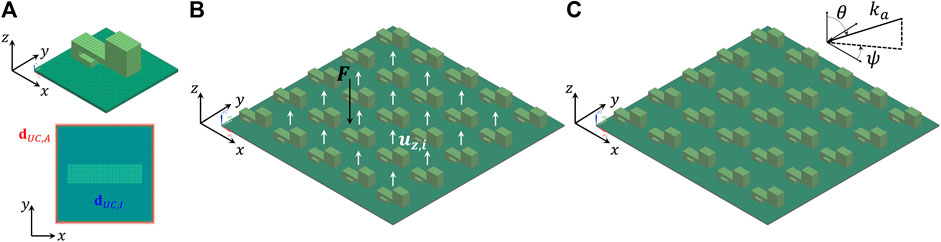
FIGURE 1. (A) LRM UC FE model (top) with highlighted interior (dUC,I) and boundary (dUC,A) DOFs (bottom), (B) finite LRM plate assembly composed of 5 × 5 UCs with input point force and output displacement locations and (C) with oblique acoustic plane wave excitation.
3 Methodology
In what follows, the sub-structuring approach is first recalled in Section 3.1. Next, the MOR on UC level is explained in Section 3.2, using BMS for interior modal reduction and GBMS for additional boundary modal reduction. The global modal reduction on finite plate assembly level is discussed in Section 3.3. Eventually, the application of the ERA within the sub-structuring MOR approach is explained in Section 3.4.
3.1 Sub-structured assembly of UCs
Consider a 2D periodic rectangular LRM plate composed of Nx × Ny identical UCs (Figure 1), modelled using the FE method. For the s-th UC FE model containing nUC DOFs, the time-harmonic equations of motion of the UC FOM read as:
With the (nUC × 1) UC DOF vector
with Ls the Boolean localization matrices of the Nx × Ny UCs and superscript T denoting the transpose, leading to the following system of equations for the finite LRM plate assembly FOM:
3.2 UC model reduction
Since the full order finite plate assembly system of equations of Eq. 3 rapidly becomes very large with increasing Nx × Ny and for fine FE UC models, model reduction is applied first on single UC level, exploiting the periodicity at hand. To this end, a single UC reduction basis VUC is constructed, which allows expressing the original UC DOFs
with:
Although
3.2.1 Interior UC modal reduction using BMS
To reduce the interior UC DOFs following the BMS approach, the UC DOFs and matrices are partitioned into the nI interior (dUC,I) and nA boundary (dUC,A) DOFs (with nUC = nI + nA) (Figure 1A):
Next, a single reduction basis VUC is set up by representing the interior UC DOFs by a superposition of a set of fixed interface normal interior modes ΦUC,I and a set of static constraint modes ΨUC,IA (Krattiger and Hussein, 2018; Krattiger et al., 2019):
where
with
3.2.2 Boundary UC modal reduction using GBMS
Following the interior modal UC MOR, a large number of UC boundary DOFs nA can potentially remain, which would still lead to large model sizes for the finite plate assembly of UC ROMs especially when using refined UC FE models. Therefore, the GBMS is used, which embeds the BMS as a first step, to also perform local boundary modal reduction on single UC level to additionally reduce the remaining UC boundary DOFs. This is done by calculating a set of normal boundary modes ΦUC,A based on the submatrices
with
where
3.2.3 Assembly of the UC ROMs
The Boolean localization matrices
It is again noted that
3.3 Global modal reduction of the assembly
Although applying UC MOR already allows to drastically reduce the model size of the finite plate assembly, the resulting system of equations can again become large when increasing the number of UCs. Therefore, an additional final global modal reduction step is applied by calculating a set of normal modes ΦT for the assembly as follows, after application of boundary conditions to the plate boundaries, as in (Mencik, 2021):
with
After solving the system of equations for all frequencies of interest, the nodal responses are found via back-projection using VT and VUC.
3.4 Elementary radiator approach
To approximate the STL of the flat rectangular LRM plates using only structural FE models, the elementary radiator approach (ERA) proposed in (Jung et al., 2017) is applied. This method was shown to enable efficient STL approximations using structural FE models of finite, baffled flat plates, without requiring an expensive coupled vibro-acoustic analysis. Here, this method is employed in combination with the above outlined GBMS-based sub-structuring approach to accelerate STL analyses of baffled, finite periodic LRM plates based on structural UC FE models. In what follows, the method is briefly described.
Consider an oblique acoustic plane wave pi with amplitude A = 1 Pa, which impinges upon the LRM plate, baffled in the xy-plane, along incidence angles θ and ψ (Figure 1C):
with (kax, kay, kaz) = −ka(sin θ cos ψ, sin θ sin ψ, cos θ) and ka the acoustic wave number. The incident sound power on the baffled plate due to this oblique plane wave excitation is:
with S the area of the finite LRM plate. The acoustic plane wave excitation is applied to the structure as a blocked pressure excitation, while the radiation resistance of the acoustic medium is neglected since the mass density of the acoustic medium air is low. Corresponding to (Fahy, 2012; Yang et al., 2017), for each frequency ω, the blocked pressure is applied as lumped normal forces at the nodes of the LRM plate’s top face:
with (xj, yj, zj) the coordinates of node j, Sj the nodal area, and with the factor 2 arising from the blocked pressure field. This leads to the corresponding nodal external forcing vectors F(ω) for the finite LRM plate assembly FOM in Eq. 3. As shown in previous work by the authors (Van Belle et al., 2019) using a fully coupled vibro-acoustic LRM FE UC model, applying the acoustic excitation on the flat LRM plate’s top face while neglecting the presence of the sub-wavelength resonators has a negligible effect on the predicted STL and is hence applied here as such as well. In order to apply the UC model reduction, the loading vectors F(ω) for each frequency are first sub-structured into the corresponding UC force vector parts
After solving the reduced system of Eq. 15 for all frequencies and back-projection to obtain the LRM plate’s nodal responses d, the transmitted sound power is computed at each frequency ω of interest from the normal nodal displacement field uz(x, y) of the flat bottom face of the LRM plate using the ERA. To this end, uz(x, y) is first subsampled in a rectangular grid of np non-overlapping rectangular patches of equal dimensions, referred to as equivalent radiators, coarser than the FE mesh. The transmitted acoustic pressure pt, evaluated at the radiating surface, is expressed as (Jung et al., 2017):
with p the index of the radiator position at which the pressure is computed, q the index of the radiators and vz,q = vz(xq, yq) = jωuz(xq, yq) the normal velocity (interpolated) at the center of radiator q. Zpq is the radiation impedance of the radiator, which is analytically computed as (Jung et al., 2017):
with Sq the area of radiator q and
with superscripts * and H respectively denoting the complex conjugate and Hermitian transpose operators, Z the np × np radiation impedance matrix and
with τ the sound power transmission coefficient. By considering multiple plane waves as multiple right hand sides in Eq. (14), and integrating the corresponding resulting oblique sound power transmission coefficients over the incidence angles, also the diffuse field STL can be computed. The ERA based STL results have been verified against fully coupled vibro-acoustic FE models in (Jung et al., 2017) and good agreement as well as high computational efficiency have been shown. Hence, the combination of ERA with fast structural response computations using the presented GBMS based sub-structuring approach in this work is proposed to enable further accelerating STL predictions of finite periodic LRM plates.
4 Results
In this section, the above described procedure is applied to a refined LRM UC FE model. After introducing the LRM design and finite plate configuration in Section 4.1, the eigenfrequency calculation on a UC and finite plate assembly level are compared when using the UC FOM as well as the UC ROMs obtained with BMS and GBMS in Section 4.2. Next, vibration responses are calculated for finite LRM plates for a point force excitation in Section 4.3, comparing model size, computational cost and accuracy. STL results for plane wave excitation are discussed in Section 4.4.
4.1 LRM description
The LRM design of (Van Belle et al., 2020) is considered, which consists of a 1 mm thick aluminium (Young’s modulus E = 70 GPa, mass density ρ = 2,700 kg/m3, Poisson’s ratio ν = 0.3) plate host structure with periodically added beam-shaped PMMA (Young’s modulus E = 4.85 GPa, mass density ρ = 1,188 kg/m3, Poisson’s ratio ν = 0.31) resonators with 0.03 × 0.03 m periodicity (Figure 1A). A constant damping loss factor η = 0.01 is considered for the entire structure in this work. The UC is discretized using 3,834 CHEXA8 linear solid elements, with a maximum element size of 1 mm and minimally three elements through the thickness of all parts. The UC FOM contains a total of 16,335 DOFs, with nI = 14,871 and nA = 1,464. As discussed in (Van Belle et al., 2020), the beam-shaped resonator is tuned with its first out-of-plane bending mode to a resonance frequency of 616 Hz and adds 39.8% mass to the host structure, which leads to a bending wave stop band between 597–656 Hz. The frequency range of interest in this work hence ranges up to a maximum frequency of 1,000 Hz.
To verify the accuracy and computational benefit of the MOR approach, a moderately sized finite LRM plate composed of 5 × 5 UCs (Figure 1B) and a larger 15 × 15 UC LRM plate are considered. A zero displacement boundary condition is imposed along the circumference of the finite plates. The resulting 5 × 5 UC plate FOM counts a total of 386,127 unknown DOFs, and the 15 × 15 UC plate FOM counts 3,497,007 unknown DOFs. The moderate 5 × 5 UC plate size allows a comparison of the ROMs with the finite LRM plate FOM within reasonable computation times, while the 15 × 15 UC plate similar to (Mencik, 2021) allows demonstrating the efficiency of the approach for larger LRM plates as compared to conventional global modal MOR.
4.2 Eigenfrequency analysis
Before assessing the vibro-acoustic forced response computations, the computation of the eigenfrequencies of the undamped UC ROMs and finite plate ROMs is first assessed for different
4.2.1 UC level
To assess the UC ROMs, the first 20 eigenfrequencies of the free, undamped UC are computed and the non-zero eigenfrequencies are compared. First, only interior UC modal reduction is applied using the BMS, considering different amounts of interior UC modes
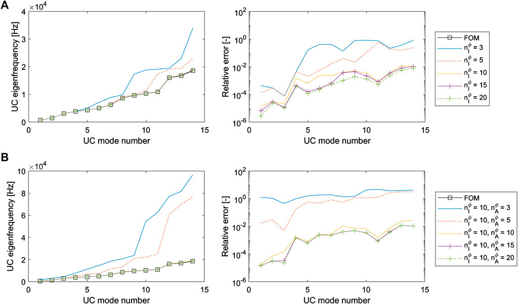
FIGURE 2. (A) Eigenfrequencies (left) and relative error of the eigenfrequencies (right) computed for the BMS reduced free UC, considering different
Next, also the UC boundary is reduced using the GBMS, considering
4.2.2 Finite plate level
To assess the finite plate ROMs, the first 60 eigenfrequencies of the clamped, undamped finite LRM plate assembly of 5 × 5 UCs are computed, up to about twice the frequency range of interest of 1,000 Hz. This comes down to evaluating E. 14 on the assembly of UC FOMs or ROMs. Again, first only interior UC modal reduction is applied for different
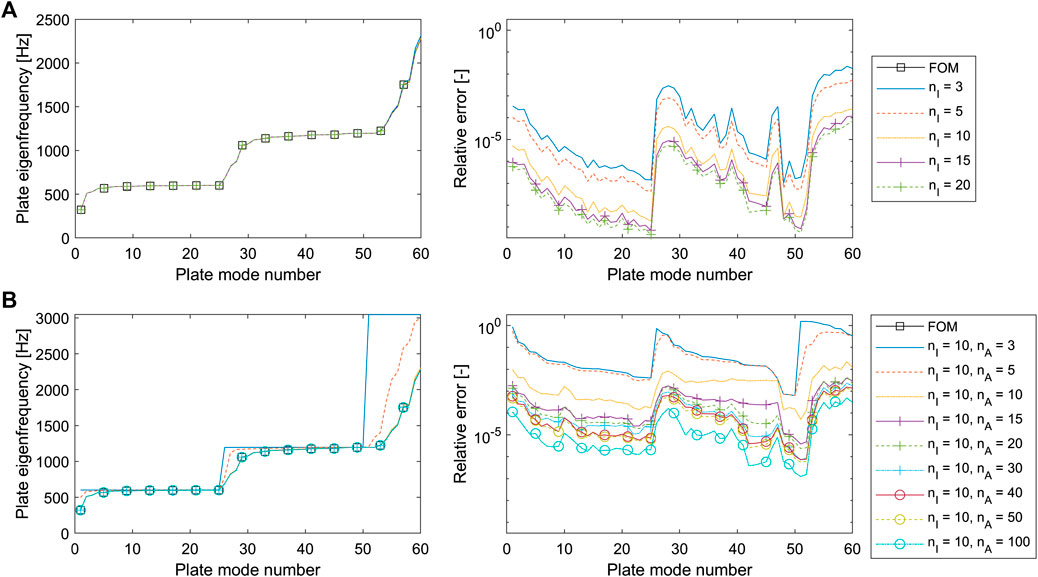
FIGURE 3. (A) Eigenfrequencies (left) and relative error of the eigenfrequencies (right) computed for the clamped finite plate assembly of 5 × 5 BMS UC ROMs, considering different
Next, the finite plate assembly of GBMS UC ROMs is assessed, considering
Table 1 gives an overview of the model sizes and timings for the FOM, BMS and GBMS UC based sub-structured clamped finite LRM plate’s modal calculation for the first 60 eigenmodes. All computations were performed on a Intel Xeon Gold 6240 CPU with 192 GB RAM. Where the BMS with

TABLE 1. Overview of 5 × 5 UC finite LRM plate FOM, BMS and GBMS based model sizes and computational times required for the model reduction, assembly and eigenmodes calculation.
The additional benefit of the UC boundary reduction in the GBMS based approach is emphasized when considering a larger, 15 × 15 UC assembly and computing the first 564 eigenmodes (Table 2) up to about twice the frequency range of interest of 1,000 Hz. Where for the 5 × 5 UC assembly, the total computation time to obtain the eigenmodes up to twice the frequency range of interest is about factor 4 faster with GBMS
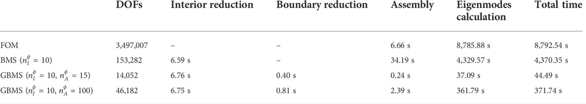
TABLE 2. Overview of 15 × 15 UC finite LRM plate FOM, BMS and GBMS based model sizes and computational times required for the model reduction, assembly and eigenmodes calculation.
4.3 Forced vibration response
For the forced response analysis, first the 5 × 5 UC finite LRM plate is considered. The plate is excited by a point force with magnitude Fz = 1 N in the out-of-plane direction at (x, y, z) = (4.15, 5.3, 0) cm, in the second UC along the x- and y-direction (Figure 1B). The RMS out-of-plane displacement response uz at the UC corners of the plate’s top face is calculated for frequencies 1–1,000 Hz with a 1 Hz step and the relative errors of the RMS responses of the finite plate ROMs are computed with respect to the finite plate FOM (Figure 4). In total, six different models are considered: FOM, FOM with global MOR, BMS based ROM
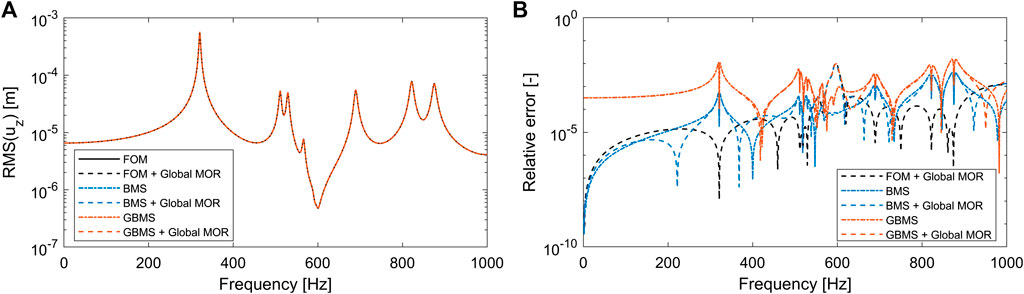
FIGURE 4. Forced vibration frequency responses (A) and relative error thereof with respect to the FOM (B) computed for the clamped finite plate assembly of 5 × 5 UCs for different ROMs. The good agreement between the results causes the frequency responses (A) to appear on top of each other.
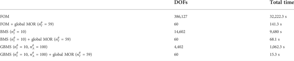
TABLE 3. Overview of FOM, BMS and GBMS UC based finite LRM plate model sizes for the clamped finite plate assembly of 5 × 5 UCs and total computational times required for the forced vibration response.
The frequency responses show very good agreement, with the stop band around 600 Hz clearly leading to vibration attenuation (Figure 4A). Overall, the BMS ROMs show good accuracy, similar to FOM with global MOR, with relative errors around 10−3 or lower (Figure 4B). As was observed for the finite assembly eigenfrequencies, GBMS leads to a slightly higher overall error of around 10−2 or lower, but still shows good agreement with the other models, especially around the stop band frequency zone of interest, where the errors of around 10−3 are lower. At low frequencies, where the response is dominated by the plate stiffness and where the wavelengths of the subsequent vibration modes are typically large, the higher errors of the GBMS might arise from the deviation of the assembly-level stiffness due to the local UC boundary modal reduction which neglects the mass and stiffness coupling with the adjacent UCs. It is noted that, inside the stop band, applying global MOR leads to slightly lower accuracy for all models for this concentrated point force excitation. This might arise from the high attenuation inside the stop band, which could require a even higher
When comparing the forced response computation times of the finite plate models with global MOR applied (Table 3), the UC boundary reduction of the GBMS based UC MOR clearly allows a considerable additional computation time reduction as compared to only interior UC reduction of the BMS based UC MOR, with over a factor 4. This is attributed to the further reduced system size after assembly of the UC ROMs which hence enables a faster global reduction step, while the computation time for UC interior and consecutive boundary reduction is small (Figure 5), as also discussed in previous section. It is noted that, in all cases, the small system size after global reduction allows a fast frequency solution.
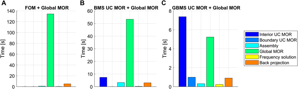
FIGURE 5. Overview of the computation times for the forced vibration response calculations of the clamped finite LRM plate assembly of 5 × 5 UCs for the FOM (A), BMS (B) and GBMS (C) based UC ROMs, all applying global MOR. The time ranges on the vertical axis differ per case for readability.
Another significant advantage of particularly the GBMS UC MOR is that, due to the smaller assembly system size, considerably less memory is required to perform the global reduction step. Especially for finite LRM plates with many UCs, this property of sub-structuring forms an important improvement and is further leveraged here by only considering a single UC. Apart from the larger system size, the typical accumulation of modes near the stop band which directly depends on the number of resonators and thus UCs also requires an increasingly higher
To further illustrate the benefit of the GBMS UC MOR in combination with global modal MOR, consider the larger clamped finite LRM plate with 15 × 15 UCs. The plate is again excited by a unit point force in the out-of-plane direction, this time at (x, y, z) = (20.3, 19.15, 0) cm in the seventh UC along the x- and y-direction. The RMS out-of-plane displacement response uz at the UC corners of the plate’s top face is calculated for frequencies 1–1,000 Hz with a 1 Hz step. To include the modes up to twice the frequency range of interest of 1,000 Hz for this LRM plate with 225 resonators, a significantly higher amount

TABLE 4. Overview of FOM, BMS and GBMS UC based finite LRM plate model sizes for the clamped finite plate assembly of 15 × 15 UCs and total computational times required to calculate the forced vibration responses of Figure 6.
Comparing the vibration responses for this 15 × 15 UC LRM plate computed with the FOM, BMS and GBMS, all combined with global MOR, good agreement is obtained (Figure 6A). For this larger LRM plate, a more prominent vibration attenuation is also observed around the predicted stop band. The relative errors of the vibration response (Figure 6B), this time computed with respect to the FOM with global MOR, lead to similar observations as for the 5 × 5 UC plate: the BMS with global MOR is more accurate than the GBMS with global MOR, except around the stop band where the accuracy is comparable. The considerably faster GBMS with global MOR leads to an overall error of around 10−2 or lower, while the error in and around stop band is about 10−3. As expected, somewhat higher errors again occur for the GBMS at lower frequencies due to the nature of the local UC boundary mode reduction.
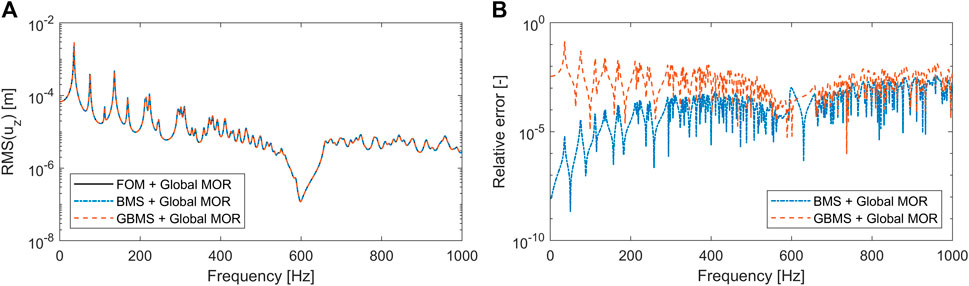
FIGURE 6. Forced vibration frequency responses (A) and relative error with respect to the FOM + global MOR (B) computed for the clamped finite plate assembly of 15 × 15 UCs for different ROMs. The good agreement between the results causes the frequency responses (A) to appear on top of each other.
4.4 Sound transmission loss
To demonstrate the fast STL computations by combining the proposed MOR approach with the ERA, first the clamped finite LRM plate composed of 5 × 5 UCs is again considered. The plate is now excited by an oblique incident plane wave at angles θ = 60°, ψ = 30° and the out-of-plane vibration response is computed for frequencies 20–1,000 Hz with a 5 Hz step. To obtain the STL, the ERA is applied, subdividing the out-of-plane nodal velocity field in a square grid of 10 × 10 square radiators with dimensions 1.5 × 1.5 cm2. The latter corresponds to half the UC size in x- and y-directions, and is twice smaller than one tenth of the acoustic wavelength λa/10 = 3.4 cm at the maximum frequency of interest of 1,000 Hz. Although a procedure was introduced in (Jung et al., 2017) to optimize the amount of radiators depending on the frequency range, a constant and relatively fine grid was considered here for all frequencies.
For the MOR, the same settings as for the 5 × 5 UC LRM plate in Section 4.3 are applied, with exception of the static enrichment, since in this case the excitation is distributed and frequency-dependent. The latter would also lead to a different enrichment vector for each frequency, which would either result in a too large reduction basis or an inefficient frequency-dependent projection step. The STL results and corresponding relative errors as compared to the FOM are shown in Figure 7, while the model sizes and computation costs are summarized in Table 5. As expected for LRM partitions with bending wave stop bands (Van Belle et al., 2019), the STL shows a clear peak around 600 Hz, near the tuned resonator frequency, followed by a characteristic STL dip. The low-frequency STL dip around 270 Hz, corresponding to the first bending mode of the clamped plate, lies slightly below 0 dB, which is due to the underlying Rayleigh integral approximation made in the ERA in combination with the small sample size. However, despite its uncoupled nature, overall the ERA enables a representative STL prediction for the considered LRM plate configuration. As observed in previous section for the vibration response predictions, also the STL shows very good agreement between all models. This is expected, since the difference in STL between the models results from the difference in vibration responses obtained with the different ROMS. The highest absolute difference of each UC ROM based model is no larger than 0.6 dB as compared to the FOM and 0.1 dB as compared to the FOM with global MOR. The GBMS based ROMs are in good agreement with the BMS, in particular in and round the stop band frequency range of interest, but show slightly higher errors away from the stop band. All ROMs show a relative error of about 10−2 or lower, with global MOR leading to a more outspoken accuracy reduction as compared to the vibration response. The latter might be attributed to the absence of static enrichment. Combined with reported mean errors arising from the ERA below 0.5 dB as compared to fully coupled vibro-acoustic FE modeling (Jung et al., 2017), the current MOR approach hence still enables accurate STL predictions.
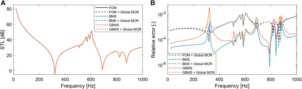
FIGURE 7. STL results (A) and relative error with respect to the FOM (B) computed for the clamped finite plate assembly of 5 × 5 UCs for different ROMs. The good agreement between the results causes the STL curves (A) to appear on top of each other.
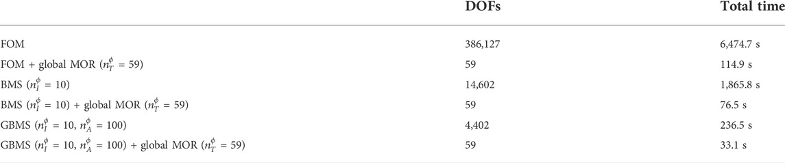
TABLE 5. Overview of FOM, BMS and GBMS UC based finite LRM plate model sizes for the clamped finite plate assembly of 5 × 5 UCs and total computational times required for the STL computations.
Comparing the model sizes and computation times in Table 5, it is again evident that the additional boundary reduction provided by the GBMS based MOR provides a significant advantage over only interior reduction in the case of BMS based MOR. In combination with global MOR, the GBMS based MOR achieves a speed-up of over a factor 3 as compared to the FOM with global MOR, and is over 2 times faster than BMS based MOR with global MOR. As illustrated in more detail in Figure 8, the apparent slightly lower speed-up of the GBMS and BMS with global MOR versus the FOM with global MOR for these STL computations as compared to the earlier vibration response computations is attributed to the fixed computation cost for the sound power evaluation using ERA, which takes about 15 s for this small 5 × 5 UC LRM plate. As no static enrichment is included for the STL computations, the global MOR step which includes the basis construction and the projection takes less time as compared to the vibration response computations for the point force loading (Figure 5). The simultaneous projection of as many loading vectors as frequencies, due to the frequency-dependency of the blocked pressure field, does not come at a high computation cost. Using the GBMS with global MOR, the cost of reducing and solving the model becomes comparable to the low cost associated with the ERA, which was already reported in detail in (Jung et al., 2017, Jung et al., 2022), while obtaining accurate predictions.
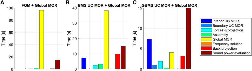
FIGURE 8. Overview of the computation times for the STL calculations of the clamped finite LRM plate assembly of 5 × 5 UCs for the FOM (A), BMS (B) and GBMS (C) based UC ROMs, all applying global MOR. The time ranges on the vertical axis differ per case for readability.
As shown earlier for the concentrated point force excitation, the acceleration of the STL predictions when using the GBMS based MOR with global reduction as compared to the BMS with global MOR and FOM with global MOR becomes even more outspoken when considering a larger 15 × 15 UC LRM plate. The STL is again computed for frequencies 20–1,000 Hz with a 5 Hz step for the same oblique plane wave excitation as before, using FOM with global MOR, BMS with global MOR and GBMS with global MOR (Figure 9). The same MOR settings as for the 15 × 15 UC LRM plate in Section 4.3 are applied, without static enrichment, and the relative error is computed against the STL results of the FOM with global MOR.
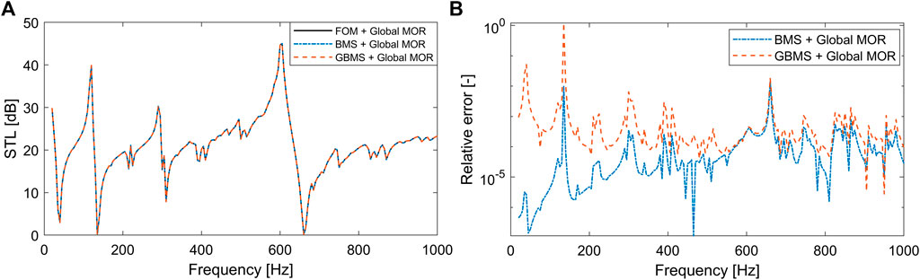
FIGURE 9. STL results (A) and relative error with respect to the FOM + global MOR (B) computed for the clamped finite plate assembly of 15 × 15 UCs for different ROMs. The good agreement between the results causes the STL curves (A) to appear on top of each other.
As expected based on the vibration response predictions, good agreement between the STL predictions of the different models is also obtained. Due to the larger plate size, the stiffness region in the STL is clearly shifted to lower frequencies, while the STL peak and dip around the stop band are more prominent. The GBMS attains an overall accuracy of around 10−2 and lower, with some exceptions at low around global modes where the STL reaches values close to 0 dB. At low frequencies, the approximation due to the local UC boundary reduction of the GBMS again leads to somewhat higher errors. As before, the BMS is overall more accurate than the GBMS, apart from the stop band region. However, as shown in Table 6, for this larger plate assembly, the GBMS provides a substantial speed-up as compared to the BMS thanks to the additional UC boundary reduction, which is again a higher gain as compared to the smaller 5 × 5 UC LRM plate. For this 15 × 15 UC LRM plate, the ERA based sound power evaluation step takes about 155 s. Combined with the GBMS, fast and accurate STL predictions of finite periodic LRM plates are hence possible.
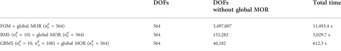
TABLE 6. Overview of FOM, BMS and GBMS UC based finite LRM plate model sizes for the clamped finite plate assembly of 15 × 15 UCs and total computational times required to calculate the STL results of Figure 9.
It is noted that, although the GBMS with global MOR provides an advantage as compared to BMS with global MOR or FOM with global MOR for an increasing number of UCs in the finite plate assembly, the UC ROM assembly as well as the required
5 Conclusion
In this paper, a Generalized Bloch Mode Synthesis based sub-structuring approach was presented for fast forced vibro-acoustic response computations of finite periodic locally resonant metamaterial plates composed of periodically repeated, identical unit cells and applied to a locally resonant metamaterial design. Contrary to classical sub-structuring, the proposed method exploits the periodicity at hand by only considering a single unit cell model. By combining the structural unit cell assembly model with an Elementary Radiator Approach, also the sound transmission loss can be computed based on the forced vibration response for distributed acoustic loading. Compared to a regular Craig-Bampton based sub-structuring approach which only applies interior modal reduction to the unit cell, as also applied in the Bloch Mode Synthesis, the additional unit cell boundary modal reduction based on the Generalized Bloch Mode Synthesis was shown to enable considerable additional system size and computation time reduction for eigenmode computations and forced vibro-acoustic response computations, with only limited accuracy loss resulting from the uncoupled boundary modal computation based on just a single unit cell. The fast eigenmode computation on assembly level is particularly interesting when performing the additional global modal reduction for locally resonant metamaterials, due to the accumulation of eigenmodes around the stop band which requires a larger global modal basis. These unit cell based fast vibro-acoustic forced response computations can next be employed to accelerate the design and optimization of finite periodic locally resonant metamaterial plates, while accounting for their finite size and the boundary conditions.
Data availability statement
The original contributions presented in the study are included in the article/Supplementary Material, further inquiries can be directed to the corresponding author.
Author contributions
LVB has implemented the method and has run the simulations. All authors have contributed to the study conceptualization and design, analysis, manuscript writing and revision. All authors have read and approved the publication of the submitted version.
Funding
The research of LB is funded by a grant (no. 1271621N) from the Research Foundation—Flanders (FWO). Internal Funds KU Leuven were gratefully acknowledged for their support. The work leading to this publication has been partially funded by the project MOR4MDesign, which fits in the MacroModelMat (M3) research program, coordinated by Siemens (Siemens Digital Industries Software, Belgium) and funded by SIM (Strategic Initiative Materials in Flanders) and VLAIO (Flanders Innovation and Entrepreneurship Agency). The Research Foundation—Flanders (FWO) is gratefully acknowledged for its support of the FWO-FAPESP research project G0F9922N.
Conflict of interest
The authors declare that the research was conducted in the absence of any commercial or financial relationships that could be construed as a potential conflict of interest.
Publisher’s note
All claims expressed in this article are solely those of the authors and do not necessarily represent those of their affiliated organizations, or those of the publisher, the editors and the reviewers. Any product that may be evaluated in this article, or claim that may be made by its manufacturer, is not guaranteed or endorsed by the publisher.
References
Aladwani, A., Nouh, M., and Hussein, M. I. (2022). State-space Bloch mode synthesis for fast band-structure calculations of non-classically damped phononic materials. Comput. Methods Appl. Mech. Eng. 396, 115018. doi:10.1016/j.cma.2022.115018
Allen, M. S., Rixen, D., Van der Seijs, M., Tiso, P., Abrahamsson, T., and Mayes, R. L. (2020). Substructuring in engineering dynamics. Heidelberg, Germany: Springer.
Boukadia, R. F., Deckers, E., Claeys, C., Ichchou, M., and Desmet, W. (2020). “A rational Krylov subspace method for the unit cell modeling of 2D infinite periodic media,” in Proceedings of ISMA, September 7–9, 2020 (Leuven: KU Leuven, Mechanical Engineering, Division LMSD, Noise & Vibration Research Group).
Boukadia, R. F., Droz, C., Ichchou, M. N., and Desmet, W. (2018). A Bloch wave reduction scheme for ultrafast band diagram and dynamic response computation in periodic structures. Finite Elem. Analysis Des. 148, 1–12. doi:10.1016/j.finel.2018.05.007
Chang, K.-J., Jung, J., Kim, H.-G., Choi, D. R., and Wang, S. (2018). An application of acoustic metamaterial for reducing noise transfer through car body panels. Tech. rep. SAE Technical Paper.
Claeys, C., Deckers, E., Pluymers, B., and Desmet, W. (2016). A lightweight vibro-acoustic metamaterial demonstrator: Numerical and experimental investigation. Mech. Syst. signal Process. 70, 853–880. doi:10.1016/j.ymssp.2015.08.029
Claeys, C., Sas, P., and Desmet, W. (2014). On the acoustic radiation efficiency of local resonance based stop band materials. J. Sound Vib. 333, 3203–3213. doi:10.1016/j.jsv.2014.03.019
Claeys, C., Vergote, K., Sas, P., and Desmet, W. (2013). On the potential of tuned resonators to obtain low-frequency vibrational stop bands in periodic panels. J. Sound Vib. 332, 1418–1436. doi:10.1016/j.jsv.2012.09.047
Cool, V., Van Belle, L., Claeys, C., Deckers, E., and Desmet, W. (2022). Impact of the unit cell choice on the efficiency of dispersion curve calculations using generalized Bloch mode synthesis. J. Vib. Acoust. 144, 1-28. doi:10.1115/1.4051817
de Melo Filho, N., Claeys, C., Deckers, E., and Desmet, W. (2020). Metamaterial foam core sandwich panel designed to attenuate the mass-spring-mass resonance sound transmission loss dip. Mech. Syst. Signal Process. 139, 106624. doi:10.1016/j.ymssp.2020.106624
Deckers, E., Jonckheere, S., Van Belle, L., Claeys, C., and Desmet, W. (2018). Prediction of transmission, reflection and absorption coefficients of periodic structures using a hybrid wave based–finite element unit cell method. J. Comput. Phys. 356, 282–302. doi:10.1016/j.jcp.2017.12.001
Decraene, C., Lombaert, G., and Reynders, E. P. (2022). Prediction of diffuse sound transmission through finite-sized periodic structures. J. Sound Vib. 528, 116851. doi:10.1016/j.jsv.2022.116851
Droz, C., Robin, O., Ichchou, M., and Atalla, N. (2019). Improving sound transmission loss at ring frequency of a curved panel using tunable 3D-printed small-scale resonators. J. Acoust. Soc. Am. 145, EL72–EL78. doi:10.1121/1.5088036
Errico, F., Tufano, G., Robin, O., Guenfoud, N., Ichchou, M., and Atalla, N. (2019). Simulating the sound transmission loss of complex curved panels with attached noise control materials using periodic cell wavemodes. Appl. Acoust. 156, 21–28. doi:10.1016/j.apacoust.2019.06.027
Fahy, F. J. (2012). Sound and structural vibration: Radiation, transmission and response. Massachusetts, United States: Academic Press.
Gruber, F. M., and Rixen, D. J. (2016). Evaluation of substructure reduction techniques with fixed and free interfaces. Strojniški vestnik-Journal Mech. Eng. 62, 452–462. doi:10.5545/sv-jme.2016.3735
Hussein, M. I., Leamy, M. J., and Ruzzene, M. (2014). Dynamics of phononic materials and structures: Historical origins, recent progress, and future outlook. Appl. Mech. Rev. 66, 040802. doi:10.1115/1.4026911
Hussein, M. I. (2009). Reduced Bloch mode expansion for periodic media band structure calculations. Proc. R. Soc. A 465, 2825–2848. doi:10.1098/rspa.2008.0471
Jung, J., Kook, J., and Goo, S. (2022). Maximizing sound transmission loss using thickness optimization based on the elementary radiator approach. Struct. Multidiscipl. Optim. 65 (4), 1–13. doi:10.1007/s00158-022-03228-7
Jung, J., Kook, J., Goo, S., and Wang, S. (2017). Sound transmission analysis of plate structures using the finite element method and elementary radiator approach with radiator error index. Adv. Eng. Softw. 112, 1–15. doi:10.1016/j.advengsoft.2017.06.001
Krattiger, D., and Hussein, M. I. (2014). Bloch mode synthesis: Ultrafast methodology for elastic band-structure calculations. Phys. Rev. E 90, 063306. doi:10.1103/physreve.90.063306
Krattiger, D., and Hussein, M. I. (2018). Generalized Bloch mode synthesis for accelerated calculation of elastic band structures. J. Comput. Phys. 357, 183–205. doi:10.1016/j.jcp.2017.12.016
Krattiger, D., Wu, L., Zacharczuk, M., Buck, M., Kuether, R. J., Allen, M. S., et al. (2019). Interface reduction for Hurty/Craig-Bampton substructured models: Review and improvements. Mech. Syst. Signal Process. 114, 579–603. doi:10.1016/j.ymssp.2018.05.031
Liu, Z., Zhang, X., Mao, Y., Zhu, Y., Yang, Z., Chan, C. T., et al. (2000). Locally resonant sonic materials. science 289, 1734–1736. doi:10.1126/science.289.5485.1734
Mencik, J.-M., and Duhamel, D. (2021). “Dynamic analysis of periodic structures and metamaterials via wave approaches and finite element procedures,” in 8th International Conference on Computational Methods in Structural Dynamics and Earthquake Engineering, June 28–30, 2021 (Athens, Greece: Institute of Structural Analysis and Antiseismic Research School of Civil Engineering, National Technical University of Athens (NTUA)).
Mencik, J.-M. (2021). Model reduction based on matrix interpolation and distorted finite element meshes for dynamic analysis of 2D nearly periodic structures. Finite Elem. Analysis Des. 188, 103518. doi:10.1016/j.finel.2021.103518
Mencik, J.-M. (2014). New advances in the forced response computation of periodic structures using the wave finite element (WFE) method. Comput. Mech. 54, 789–801. doi:10.1007/s00466-014-1033-1
Palermo, A., and Marzani, A. (2020). A reduced Bloch operator finite element method for fast calculation of elastic complex band structures. Int. J. Solids Struct. 191, 601–613. doi:10.1016/j.ijsolstr.2019.12.011
Pires, F. A., Wandel, M., Thomas, C., Deckers, E., Desmet, W., and Claeys, C. (2022). Improving the sound transmission loss of an aircraft ceiling panel by locally resonant metamaterials. Tech. rep. SAE Technical Paper.
Rouleau, L., Deü, J.-F., and Legay, A. (2017). A comparison of model reduction techniques based on modal projection for structures with frequency-dependent damping. Mech. Syst. Signal Process. 90, 110–125. doi:10.1016/j.ymssp.2016.12.013
Sangiuliano, L., Claeys, C., Deckers, E., and Desmet, W. (2020). Influence of boundary conditions on the stop band effect in finite locally resonant metamaterial beams. J. Sound Vib. 473, 115225. doi:10.1016/j.jsv.2020.115225
Sangiuliano, L., Reff, B., Palandri, J., Wolf-Monheim, F., Pluymers, B., Deckers, E., et al. (2022). Low frequency tyre noise mitigation in a vehicle using metal 3D printed resonant metamaterials. Mech. Syst. Signal Process. 179, 109335. doi:10.1016/j.ymssp.2022.109335
Song, Y., Wen, J., Tian, H., Lu, X., Li, Z., and Feng, L. (2020). Vibration and sound properties of metamaterial sandwich panels with periodically attached resonators: Simulation and experiment study. J. Sound Vib. 489, 115644. doi:10.1016/j.jsv.2020.115644
Van Belle, L., Claeys, C., Deckers, E., and Desmet, W. (2017). On the impact of damping on the dispersion curves of a locally resonant metamaterial: Modelling and experimental validation. J. Sound Vib. 409, 1–23. doi:10.1016/j.jsv.2017.07.045
Van Belle, L., Claeys, C., Deckers, E., and Desmet, W. (2019). The impact of damping on the sound transmission loss of locally resonant metamaterial plates. J. Sound Vib. 461, 114909. doi:10.1016/j.jsv.2019.114909
Van Belle, L., de Melo Filho, N., Claeys, C., Deckers, E., Naets, F., Desmet, W., et al. (2020). Fast metamaterial design optimization using reduced order unit cell modeling. Proceedings of ISMA.
van Ophem, S., Deckers, E., and Desmet, W. (2018). Efficient assembly of unit cells with Krylov based model order reduction. Proceedings of ISMA, September 17–19, 2018 (Leuven: KU Leuven, Mechanical Engineering), 445–456.
Xi, C., and Zheng, H. (2021). Improving the generalized Bloch mode synthesis method using algebraic condensation. Comput. Methods Appl. Mech. Eng. 379, 113758. doi:10.1016/j.cma.2021.113758
Xiao, Y., Wen, J., Wang, G., and Wen, X. (2013). Theoretical and experimental study of locally resonant and Bragg band gaps in flexural beams carrying periodic arrays of beam-like resonators. J. Vib. Acoust. 135, 041006. doi:10.1115/1.4024214
Xiao, Y., Wen, J., and Wen, X. (2012). Sound transmission loss of metamaterial-based thin plates with multiple subwavelength arrays of attached resonators. J. Sound Vib. 331, 5408–5423. doi:10.1016/j.jsv.2012.07.016
Keywords: metamaterials, unit cell, sub-structuring, model order reduction, vibration, sound transmission
Citation: Van Belle L, Claeys C, Desmet W and Deckers E (2022) Fast vibro-acoustic response computations for finite periodic metamaterial plates using a generalized Bloch Mode Synthesis based sub-structuring approach. Front. Mech. Eng 8:1031899. doi: 10.3389/fmech.2022.1031899
Received: 30 August 2022; Accepted: 07 October 2022;
Published: 11 November 2022.
Edited by:
Fuyin Ma, Xi’an Jiaotong University, ChinaReviewed by:
Mahmoud Hussein, University of Colorado Boulder, United StatesHuina Mao, Royal Institute of Technology, Sweden
Pei Sun, Shanghai University of Engineering Sciences, China
Copyright © 2022 Van Belle, Claeys, Desmet and Deckers. This is an open-access article distributed under the terms of the Creative Commons Attribution License (CC BY). The use, distribution or reproduction in other forums is permitted, provided the original author(s) and the copyright owner(s) are credited and that the original publication in this journal is cited, in accordance with accepted academic practice. No use, distribution or reproduction is permitted which does not comply with these terms.
*Correspondence: Lucas Van Belle, bHVjYXMudmFuYmVsbGVAa3VsZXV2ZW4uYmU=