 Ji-Woong Park1,2*
 Shirin Jouzdani3
 Tom Tzanetakis1
 Henry Schmidt3
 William Atkinson3
 Jeffrey Naber3
 Yuanjiang Pei1
 Feng Tao4Rajesh Garg4David Langenderfer4
 Yu Zhang1Sibendu Som2
- 1Aramco Americas: Aramco Research Center–Detroit, Novi, MI, United States
- 2Argonne National Laboratory, Lemont, IL, United States
- 3Michigan Technological University, Houghton, MI, United States
- 4Cummins Inc., Columbus, IN, United States
Characteristics of diesel sprays injected through Cummins medium-duty ISB injectors were studied experimentally in an optically accessible constant-volume combustion vessel. The experiments were performed with ultra-low-sulfur diesel (ULSD) under non-reacting and non-vaporizing conditions, including different ambient gas densities (23–65 kg/m3), injection pressures (500–1,500 bar), and injection duration times (0.5–1.5 ms). The ambient temperature of the vessel was maintained at a room temperature of 313 K for all the tests. A systematic comparison was made between single-hole (SH) and multi-hole (MH) injector configurations. A plume-to-plume variation in spray penetration length was observed for various operating conditions. A substantial deviation was observed for a specific hole against the averaged plume, indicating that arbitrary selection of the plume index may result in inaccurate spray characterization of the MH injector. The penetration length of the MH injector was shorter than that of the SH injector under the same operating conditions, indicating that a spray model calibrated on SH injector data may not accurately predict the transient spray behavior of the MH injector in practical engine simulations. A square-root correlation of the spray penetration length was applied for both the SH and MH injectors. The spray penetration length and dispersion angles of the ISB SH injector were also compared with those of the heavy-duty Cummins ISX SH injector. While the ISX SH injector showed a faster penetration than the ISB SH injector, the dispersion angle was similar. The differences in spray penetration between ISB and ISX injectors followed the expected trend based on their nozzle hole diameters.
1 Introduction
Diesel fuel has been widely used in various transportation sectors, including marine, agricultural, and heavy-duty on-road applications. The reason it provides a large portion of the energy supply in the transportation sector is mostly attributed to its high energy density, as well as the well-established distribution network for refueling (U.S. Energy Information Administration, 2021; International Energy Agency, 2021). However, strict emission regulations with increased demand for reduced fuel consumption have prompted researchers to seek next-generation diesel engines that improve fuel efficiency and reduce pollutant emissions. Advanced injector and combustion technologies include, but are not limited to, high-pressure common-rail systems (Sellnau et al., 2019), exhaust-gas recirculation (EGR) (D’Ambrosio and Ferrari, 2015), thermal barrier coatings (Garcia, 2021), advanced air handling systems with Miller cycle intake valve strategies (Garcia, 2021), multiple injections strategies (Choi and Park, 2022; Liu et al., 2022), and piston-bowl shape optimization (Subramanian et al., 2016; Guo Z. et al., 2020). To improve thermal efficiency and reduce emissions, an accurate understanding of spray characterization is critical because it determines fuel-air mixing and piston/wall-wetting phenomena (Kook and Pickett, 2012), which consequently affect combustion and emission processes.
Extensive experimental and computational studies on automotive injector sprays have been performed by several research groups (e.g., Siebers, 1998; Siebers, 1999; Arcoumanis et al., 2000; Siebers and Higgins, 2001; Kennaird et al., 2002; Senecal et al., 2003; Tang et al., 2018; Chen et al., 2019; Tzanetakis et al., 2021; Yi et al., 2021; Engine Combustion Network (ECN), 2022; Tzanetakis et al., 2022). Prior to the end of the 1990s, spray characterization was performed by varying the injection strategies, including injection pressure, back chamber pressure, orifice diameter, and the number of orifices (Naber and Siebers, 1996; Siebers, 1998; Tennison et al., 1998; Siebers, 1999; Arcoumanis et al., 2000; Siebers and Higgins, 2001; Kennaird et al., 2002). Since then, extensive work has been performed in this area, much of it by the Engine Combustion Network (ECN) (Engine Combustion Network (ECN), 2022). In 2011, the first proceeding of ECN was initiated with a particular focus on internal nozzle flow, near-field (i.e., nozzle tip) spray behavior, vaporizing sprays, ignition, flame morphology, and emissions. Through collaboration among a variety of research organizations, the ECN has established a well-organized database covering a wide range of operating conditions, injector specifications, experimental facility effects, and so on. These data are available online and have been widely used as a validation set to develop predictive diesel spray models used for computational fluid dynamics (CFD) simulations (Pastor et al., 2012; Pomraning et al., 2014; Pei et al., 2015; Payri et al., 2016a; Pastor et al., 2018; Tang et al., 2018; Battistoni et al., 2019; Guo H. et al., 2020; García-Oliver et al., 2020). The ECN has considered various diesel research nozzle configurations (Sprays A, B, C, and D) based on a common rail fuel injector generated by Bosch (Engine Combustion Network (ECN), 2022). Single-hole (SH) injectors of Sprays A, C, and D have different nominal orifice diameters of 90, 200, and 186 μm, respectively. The Spray B configuration is a 3-hole injector with an orifice diameter of 90 μm, the same diameter as Spray A. The specifications of ECN diesel research injectors are briefly summarized in Table 1. These variations allowed systematic experimental investigation of the impact of multiple holes (Spray A vs. B) (Pickett et al., 2013; Jung et al., 2015; Payri et al., 2016a) and nozzle diameter (Spray A vs. C and D) on spray characterization (Pastor et al., 2012; Payri et al., 2014; Payri et al., 2016b; Pastor et al., 2018; García-Oliver et al., 2020). Several research institutions have studied these injectors using different measuring techniques. However, the number of holes in a practical engine is larger than the number used in ECN research injectors [e.g., 7 holes (Jin et al., 2020) or even more than 10 holes (Dong et al., 2016; Zhai et al., 2021a)]. Therefore, the sprays from a practical injector with a more representative number of nozzle holes exposed to engine-relevant operating conditions need to be investigated.
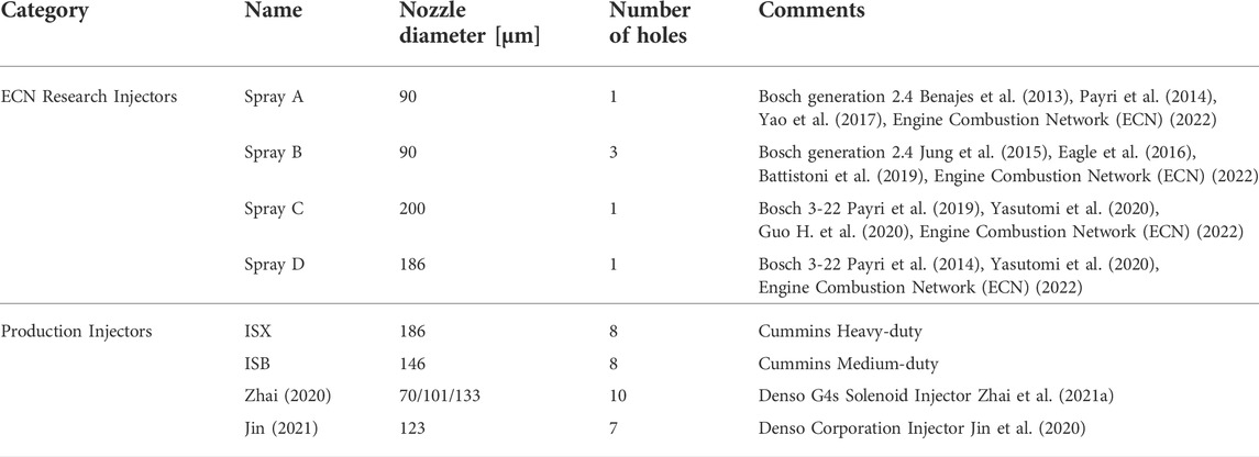
TABLE 1. Specification of diesel injectors used by the ECN, in the literature and this study.
In addition to the ECN-based research injectors, many research groups have investigated the spray characterization of production multi-hole (MH) injectors (Dong et al., 2016; Jin et al., 2020; Zhai et al., 2021a) and compared them to SH injectors (Moon et al., 2015; Jin et al., 2020). A few studies using the production MH injectors are summarized in Table 1. Dong et al. (2016) investigated the effects of the nozzle configuration (SH and MH) and injection quantity (or injection duration) both experimentally and numerically. The SH injector showed a longer penetration length than the MH injector, while the MH injector showed a larger spray cone angle of the individual plume of interest than the SH injector. CFD simulations were carried out using the commercial software AVL FIRE, Version 2013 (AVL FIRE, 2013) to further provide the internal flow characteristics. Simulation results showed that the SH injector exhibited symmetric film-type cavitation, while the MH injector showed asymmetric cavitation behavior due to the internal spiral and streamwise counter-rotating flow. Jin et al. (2020) also compared the SH and MH injectors in a vaporizing spray condition at an ambient temperature of 800 K. Under the same rail pressure, the sac pressure of the SH injector increased faster than the MH injector, resulting in a larger velocity at the hole exit and, thereby, faster vapor penetration due to the enhanced air entrainment. By decreasing the injection pressure of the SH injector, they found that the SH and MH injectors showed similar injection rate profiles and similar vapor penetration. Interestingly, even if both types of injectors observed similar injection rates, nozzle exit velocity, and spray tip penetration, the SH injector showed a smaller angle than the MH injector, indicating the crucial role of internal nozzle flow on spray characteristics. Zhai et al. (2021a) investigated the effect of the nozzle hole diameter (70, 101, and 133 μm) on non-evaporating spray characteristics under high injection pressures (i.e., 1,000, 2,000, and 3,000 bar). At the same injection pressure, the larger diameters showed faster penetration and a slightly larger spray angle due to the larger effective nozzle flow area, momentum, turbulent energy, and enhanced entrainment capacity. In contrast, for the same injector diameter (70 μm), the higher injection pressures showed faster penetration while the spray angle remained constant. Also, better air-fuel mixing was observed in high-pressure conditions due to the enhanced entrainment rate. Furthermore, several experimental (Moon et al., 2015; Huang et al., 2017; Torelli et al., 2018) and numerical (Torelli et al., 2017a; Zhao et al., 2017) studies were performed to elucidate the internal nozzle flow and eccentric needle motion effects on MH diesel spray injectors. As discussed above, while extensive work has been conducted using the ECN-based research injectors, the spray behavior of practical MH injectors with a larger number of holes and different orifice diameters may be quite complex. As such, the spray characterization of a practical or production MH injector and comparison with a representative SH injector are needed.
It is also worth noting that the spray penetration length can be measured in vaporizing/non-vaporizing and reacting/non-reacting conditions depending on the ambient temperature and oxygen availability, which are all summarized in Table 2. The reacting and vaporizing condition (R/V) is a more practical engine-relevant condition than the other two cases, but it inherently involves complex physics, including break-up/atomization, vaporization, combustion, and their interactions. In contrast, the non-reacting/non-vaporizing condition (NR/NV) can be made by filling the chamber with nitrogen at a low ambient temperature, less than the initial boiling point of the injected liquid. Therefore, this operating condition mainly involves spray break-up/atomization processes with minimal vaporization and combustion effects. Experimental data measured in these scenarios can provide valuable insight for investigating spray characterization. Also, the measured experimental data can be a useful input for the spray break-up model, evaporation model, and combustion model validations to develop a predictive engine computational model. As a baseline and first step, the current study focuses on the NR/NV condition, while the other scenarios will be reported in future works.
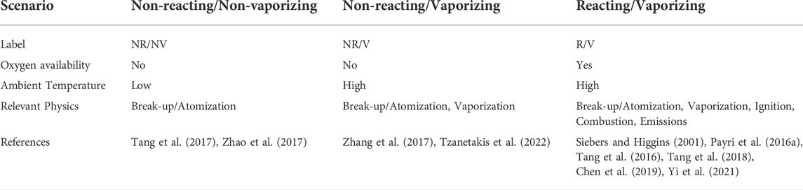
TABLE 2. Various experimental scenarios for spray characterization.
In prior works (Dong et al., 2016; Jin et al., 2020; Zhai et al., 2021a), a specific plume of interest was chosen to represent the spray penetration of MH injectors for easier optical access to characterize the spray behavior. Due to complex internal nozzle flows and cavitation phenomena, diesel MH injectors may experience plume-to-plume spray variations (Nesbitt et al., 2011; Jung et al., 2015; Huang et al., 2017; Torelli et al., 2018). Thus, an arbitrarily selected plume of interest may not properly capture nominal spray behavior, which is necessary for predictive CFD model development. Also, the effects of nozzle-hole diameter on the spray penetration and its comparison between SH and MH practical injectors are of great interest for developing advanced diesel combustion strategies.
In the current study, the experimental spray characterization was performed by measuring the spray penetration length of the MH injector of a Cummins medium-duty ISB production engine. The plume-to-plume variation is discussed first, followed by a parametric evaluation of the spray penetration length under a wide range of engine-relevant conditions. The ISB SH injector’s spray penetration length and dispersion angle were compared with those of a heavy-duty ISX SH injector to evaluate the different injector specifications (e.g., nozzle-hole diameter, etc.). Finally, the spray penetration length of the MH injector was compared with that of the SH injector to highlight the difference between them. An empirical spray penetration correlation relating to the SH and MH injectors is also presented. The experimental measurements and analysis data deduced from the current work provide detailed information on the spray behavior under practical engine configurations and useful input to further validate and improve the spray model.
2 Materials and methods
2.1 Fuel specifications
The properties of the certified diesel fuel, ultra-low-sulfur diesel (ULSD), used for the experiment were measured based on the fuel sample from Haltermann Solutions (Tzanetakis et al., 2022) and are summarized in Table 3.
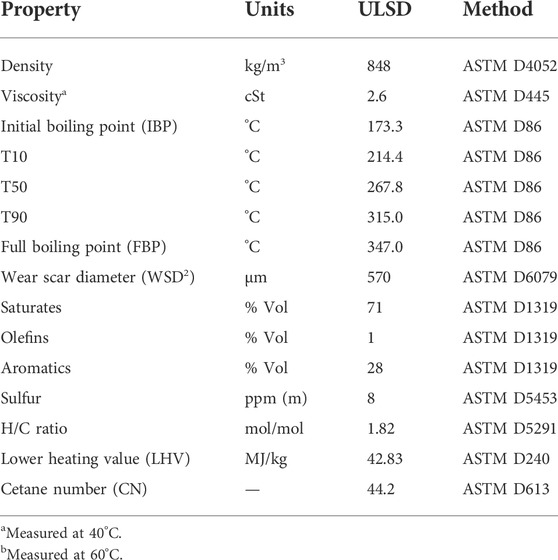
TABLE 3. Fuel properties (measured based on the sample fuel from Haltermann solutions).
2.2 Experimental setup
A constant-volume (CV) combustion chamber with an optically accessible window was utilized where the vessel volume was 1 L. The charge temperature was set to 40°C, which is below the initial boiling point (IBP) of 173°C, as shown in Table 3, to minimize the vaporization.
The liquid spray penetration length can be measured using different techniques, including shadowgraph (Tang et al., 2017; Zhang et al., 2017), Mie scattering (Zhang et al., 2017), and diffuse back-illumination (DBI) (Pickett et al., 2013; Zhai et al., 2021b). While these techniques can be used to measure for the SH injector, only Mie scattering is applicable for the MH injector because we aimed to measure the front view images rather than the side view. Liquid phase spray was visualized using the Mie-scattering technique as shown in the schematic experimental apparatus seen in Figure 1(A–B). By scattering light off the fuel droplets using two digital pulsed light-emitting diodes (LEDs), the liquid portion of the spray could be visualized and captured with a high-speed digital camera (FASTCAM SA1.1). Details of measurement techniques can be found in several studies (Nesbitt et al., 2011; Zhang et al., 2017). The injector was installed backside of the CV and could be observed from the front and side observation windows. The spray penetration length of the SH injector was measured from the side observation window, while that of the MH injector was measured from the front view with consideration of the angled spray based on the injector orientation.
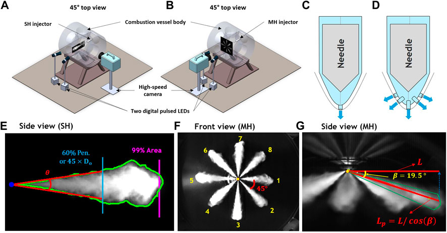
FIGURE 1. Optical setup of the Mie-scattering imaging system of (A) single-hole and (B) multi-hole injectors for the non-reacting, non-vaporizing tests. Schematic of (C) single- and (D) multi-hole injectors. (E) The side view of a single-hole (SH) injector with different definitions of spray penetration lengths (99% area) and dispersion angles (60% pen or 45×Do). The (F) front and (G) side views of the multi-hole (MH) injector with plume index by the determination of the actual penetration length (
2.3 Injectors
Specifications and schematics of the SH and MH injectors are summarized in Table 4 and Figure 1(C–D), respectively. The MH injector was a Cummins XPI ISB product injector, which has eight nozzle holes and an umbrella spray angle of 141°. The SH injector was specifically designed for this study, being intended to mimic the dynamics of the spray through one hole of the MH injector. The SH injector has an orifice along the injector body center axis, as seen in Figure 1C. In contrast, the MH injector has multi-holes off the center axis, as shown in Figure 1D. Nevertheless, due to differences in their internal nozzle structures (Asztalos et al., 2022), the dynamics of sprays exiting the orifice of the SH injector may deviate significantly from that of the MH injector.
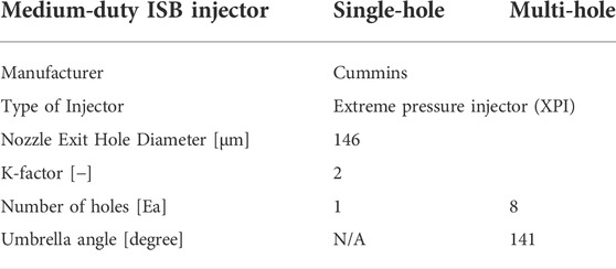
TABLE 4. Injector specification of the medium-duty ISB single- and multi-hole injectors.
2.4 Image and data processing
Figures 1F,G shows the sampled images of the SH and MH injectors. The spray penetration length was defined by 99% of the total spray enveloped area for the SH injector, and the maximum x-location of the perimeter was used for the MH injector. A brief summary of the image processing procedure is as follows:
1. Read the spray images frame by frame.
2. Subtract the background from the raw image.
3. Apply Wiener filter where low pass filters yield a grayscale image that has been degraded by constant power additive noise.
4. Evaluate the threshold using Otsu’s method for each image frame to define the threshold applied to all images.
5. Convert grayscale to a binary of black and white images using the threshold.
6. Evaluate spray penetration length.
7. Evaluate the dispersion angle (
a. 60% of maximum spray penetration (60% pen)
b. 45 times the orifice diameter (
The 60% pen can capture the far-field spray phenomena well and has been widely adopted in the literature (Tang et al., 2017; Zhang et al., 2017). The alternative definition of
A schematic of the MH spray injector orientation, plume index, and the measurement of the actual spray penetration length is shown in Figure 1F,G. The multi-holes are evenly oriented at 45°, and the spray penetration length was measured from the front view. The spray plumes are oriented 19.5° off the plane of the injector, and therefore, the actual penetration length (
Eq. 1 Correction of the spray penetration length of the MH injector
where
Figure 2 shows a workflow to determine the spray penetration length from the MH injector.
1. The spray penetration length was experimentally measured in three tests, and the mean penetration length of each plume was first evaluated.
2. A plume-averaged penetration length was obtained as denoted by the thick red line.
3. A representative plume index was chosen by comparing the root-mean-square deviation (RMSD) of each plume penetration length with the plume-averaged penetration length.
4. The start-of-injection (SOI) was decided by fitting a square-root function against the first three measurements in the penetration curve to obtain the point of zero penetration.
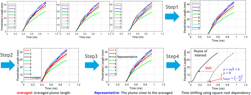
FIGURE 2. Workflow for the determination of SOI and the time origin alignment for spray penetration length of the multi-hole injector.
Following steps 1–4, the spray penetration length from different operating conditions was systematically investigated.
2.5 Test conditions
Table 5 summarizes the experimental test conditions used in this study. The measured experimental data can provide valuable inputs for the engine spray model community because the evaporation effect can be avoided. The nozzle temperature was 15°C, and pure nitrogen (N2) was used to backfill the vessel.
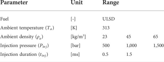
TABLE 5. Experimental test conditions.
3 Results and discussion
3.1 Spray characterization: Multi-hole ISB injector
3.1.1 Statistical plume-to-plume variation
Unlike the SH injector where the liquid spray is ejected from only one hole, the MH injector includes multiple holes with either symmetrical or asymmetrical hole configurations. Also, the SH injector has the orifice along the vertical axis with the injector body, but the orifices are not along the injector center axis in the MH injector. The different hardware characteristics may affect the in-nozzle flow and needle motion, thereby potentially resulting in different spray penetration behaviors.
Figure 3A shows the plume index in the MH injector where the starting index is located on the right side, and the index was assigned in a clockwise direction. Figure 3B shows the spray penetration lengths of each plume with different colors, with the averaged plume marked with a thick red line, following the workflow in Figure 2. While the penetration lengths among all eight holes showed similar behavior at the early stage before a shifted time (
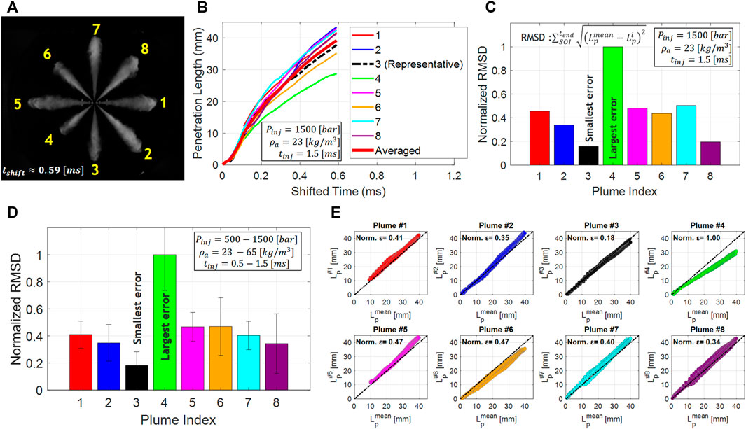
FIGURE 3. (A) Visualized spray penetration at a shifted time
Eq. 2. The root-mean-square deviation (RMSD) between each plume and the averaged plume
where
3.1.2 Effect of operating conditions on the spray penetration
The spray penetration length has been widely studied using the SH injector (Naber and Siebers, 1996; Tang et al., 2017; Zhang et al., 2017), and the following equation has been developed (Naber and Siebers, 1996):
Eq. 3. The empirical equation for the spray penetration length (S)
where
Figures 4A–C shows the effects of (A) ambient density, (B) injection pressure, and (C) injection duration on the spray penetration length at wide ranges of engine-relevant operating conditions. The SOI is obtained following the procedure in Figure 2, and the averaged plume penetration lengths from the MH ISB injector are plotted as functions of the shifted time. Figure 4A shows the spray penetration length with different ambient density conditions at a fixed injection pressure of 1,500 bar and an injection duration of 1.5 ms. The higher penetration length was observed at lower ambient density conditions, as inferred by Eq. 3. The effects of injection pressure on the spray penetration length were also found following the general trend expressed by Eq. 3, as seen in Figure 4B, indicating that the governing physics of the spray penetration of the MH injector is similar to the SH injector. On the other hand, the injection duration from 0.5 to 1.5 ms did not show a noticeable difference, as seen in Figure 4C.
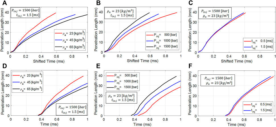
FIGURE 4. The averaged multi-hole spray penetration length as functions of (A–C) shifted time and (D–F) time, at various operating conditions: effect of, ambient density (
While the general spray penetration lengths showed similar trends between the SH and MH injectors, the different nozzle configurations may have caused a non-negligible impact on the spray penetration, as seen in Figures 1C,D. In order to investigate this point, the spray penetration length was re-plotted against the original time without the time shift in Figures 4D–F. At an injection pressure of 1,500 bar, the spray penetration curves of different ambient densities and injection durations showed a similar SOI of t = 3.7 ms. However, the spray penetration in lower injection pressure conditions showed delayed SOIs corresponding to 0.40 and 0.46 ms for 1,000 and 500 bar, respectively. This indicates that for the lower injection pressure conditions, the rate of needle lift or sac pressure rise may be slower, resulting in a delayed SOI (i.e., longer hydraulic delay) and a slower ramp-up during the initial rate-of-injection (ROI) profile, as observed in Dong et al. (2016) and Jin et al. (2020). Overall, the effects of the ambient density, injection pressure, and injection duration of the MH spray penetrations can be explained based on the empirical equation as seen in Eq. 3, developed based on the SH injector.
Figure 5A–D shows the 2D snapshot from the bottom side view for various operating conditions to highlight the effects of the injection pressure (Case B), ambient density (Case C), and injection duration (Case D). All operating conditions showed apparent plume-to-plume variations, as reported in Figure 3C, where Plume #4 has a noticeably shorter spray penetration length than others, and Plume #3 exhibits the nominal spray penetration behavior compared with other plumes. These images confirm that an arbitrarily selected plume index (e.g., Plume #4) may not represent the averaged plume behavior. Interestingly, a similar asymmetric spray penetration trend was observed in all cases, indicating that it must be associated with hardware characteristics, e.g., different orifice diameters or in-nozzle flow characteristics.
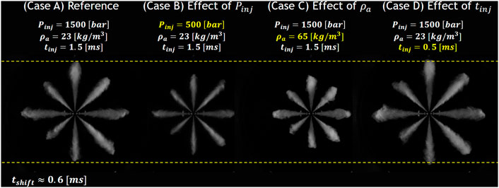
FIGURE 5. Visualization of the multi-hole spray penetration length observed from the front view in various operating conditions.
In parallel work, the same series of the injector with a different part number was scanned using a high-resolution X-ray (Sforzo et al., 2022) to generate a realistic geometry, and applied to in-nozzle flow CFD simulations (Asztalos et al., 2022). With a gasoline-like fuel, a similar plume-to-plume variation was observed in particular nozzles [e.g., Orifices #3 and #4 as denoted in Asztalos et al., 2022], indicating that the observation is not likely due to malfunctioning of the injector. In addition, we investigated other MH injectors (e.g., heavy-duty ISX) in our previous work and observed similar plume-to-plume variations in the mass flow ROI. Variabilities exceeded what was expected from the variation in geometry (i.e., hole area) alone and were strongly correlated with the eccentric needle motion (i.e., wobble) inside the injector.
3.1.3 Evaluation of an arbitrary plume index
As shown in Figure 5 and in the spray penetration statistics in Figure 3C–E, the plume-to-plume variation of the medium-duty ISB injector was noticeably different. A nominal trend was captured using Plume #3, while a large difference was evident in Plume #4. To further verify the importance of the plume index selection, Figure 6 shows the spray penetration length of averaged plume penetration compared with differently selected plumes of interest for selected operating conditions. Note that the penetration of Plumes #1 and #5 started more slowly than other plumes because of the object reflected in the visualized image at the early stages. These points were excluded when the averaged penetration length was calculated. As expected, a significantly deviated trend was obtained from Plume #4, where the largest difference was observed, as seen in Figure 3C–E. The comparisons of the spray penetrations from each hole show clear plume-to-plume variation, further demonstrating that arbitrarily selected plumes can mislead the spray characterization. To be specific, if Plume #8 or #7 had been selected as a target plume, the relative injection pressure effects could not have been captured. Interestingly, Plume #3 showed a statistically nominal plume that followed the averaged plume behavior. Thus, once plume-to-plume variation is systematically investigated, a specific plume index can be selected and used to characterize the spray penetration behavior in the MH injector.
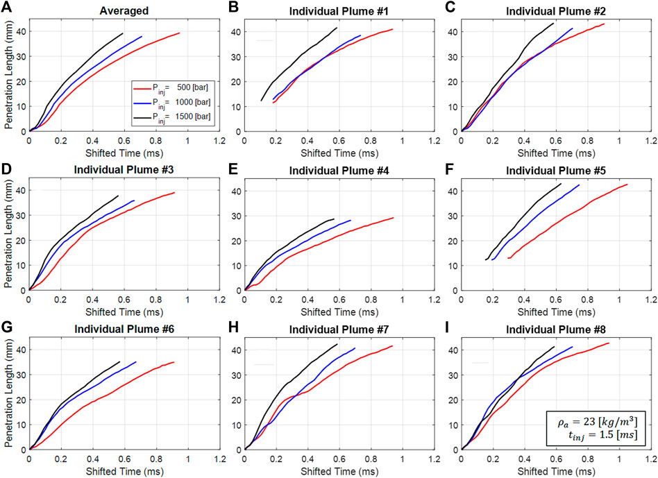
FIGURE 6. Spray penetration length of the multi-hole injector with different definitions of plumes of interest: (A) averaged plume behavior (solid line), (B–I) Plumes #1–8, at an ambient density of 23 kg/m3 and injection duration of 1.5 ms.
3.2 Spray characterization: Single-hole ISB injector
In this section, an SH medium-duty ISB injector is systematically described. While only the spray penetration length was measured for the MH injector, both dispersion angle and spray penetration length were measured for the SH injector. Also, two different definitions of the dispersion angle were evaluated to elucidate their difference.
Figure 7A,B shows the determination of the dispersion angle (
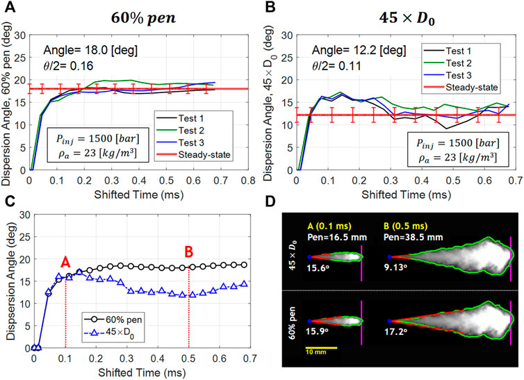
FIGURE 7. Dispersion angle of the single-hole injector from different definitions: (A) 60% of maximum penetration (60% pen) and (B) 45 times the orifice diameter (
3.3 Comparison between single- and multi-hole ISB injectors
Figure 8 compares spray penetration lengths between the medium-duty SH and MH injectors. As seen in Figure 8A, for the same operating condition, the SH injector (black circle) showed faster spray penetration than the MH injector (red triangle). In particular, the MH injector showed a smaller initial slope (d
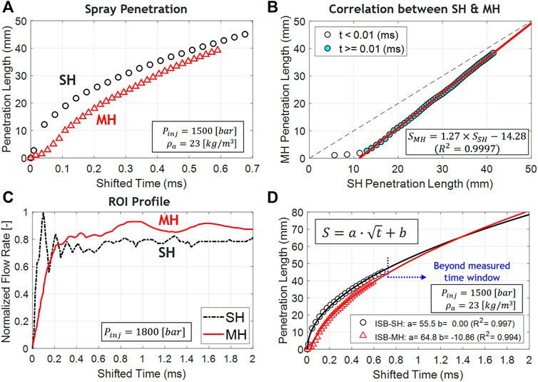
FIGURE 8. (A) Comparison of spray penetration between medium-duty SH (black) and MH (red) injectors. (B) Scatter plot of the penetration length of the SH and MH injectors with a linear correlation curve. (C) Normalized rate-of-injection (ROI) profiles using the SH and MH injectors at an injection pressure of 1,800 bar. (D) Spray penetration correlation obtained for the SH and MH injectors.
3.4 Comparison between medium-(ISB) and heavy-(ISX) duty single-hole injectors
The key injector specifications of the heavy-duty (ISX) and medium-duty (ISB) injectors are summarized in Table 6. The ISB injector has a smaller nozzle exit hole diameter and a slightly larger K-factor than the ISX injector. The discharge coefficient was not available for the ISB SH injector, while that of the ISX SH injector had a value of 0.94 (Tang et al., 2017). Both injectors consisted of a solenoid-driven, hydraulically lifted main needle, and the hole was along the central axis of the injector, as seen in Figure 1B.
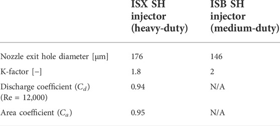
TABLE 6. Injector specification of the heavy- and medium-duty single-hole injectors.
Figure 9A compares dispersion angles with the 60% pen definition between ISX and ISB injectors. The two injectors showed very similar dispersion angle results at the steady state, and the relative difference was only 1.7%. Figure 9B shows the measured dispersion angles from the ISX and ISB injectors compared with the existing measurements with different orifice diameters from the previous studies (Naber and Siebers, 1996). The correlation equation was also plotted with 1-deg bounds. The measured values from ISB and ISX injectors show good alignment with other measurements and correlation within 1-deg bounds. Figure 9C shows the spray penetration length between ISB and ISX SH injectors, where the symbols denote the experimental measurements while the solid lines are the fitted equation with a square-root function. Both injectors showed good agreements with the empirical equations with high R2 values (>0.99), indicating that both injectors follow a square-root dependency due to the air entrainment into the spray envelope, similar to prior work (Naber and Siebers, 1996; Tang et al., 2017; Tang, 2018). The ISX injector showed faster penetration than the ISB injector as spray penetration length is proportional to the orifice diameter, as expressed in Eq. 3, under the same operating conditions (e.g.,
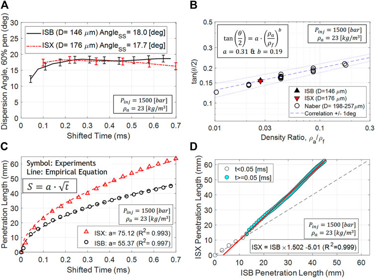
FIGURE 9. (A) Comparison in dispersion angle (60% pen) between the ISX and ISB injectors where subscript SS indicates quasi-steady state. (B) Comparison with previous studies (Naber and Siebers, 1996) where
To further investigate the different spray penetration behaviors between the ISB and ISX injectors, the scatter plots of the two injectors are shown in Figure 9D. As can be seen, these two injectors show a linear trend at the early stage until t < 0.05 ms because both injectors have a single hole along the injector axis. As such, the internal flow characteristic is quite similar. After the early stage, the ISX injector started to penetrate faster than the ISB injector due to different air entrainment effects caused by a larger injector nozzle diameter (176 µm for ISX vs. 146 µm for ISB).
4 Summary
Experimental diesel spray characterization was performed in an optically accessible, constant-volume combustion chamber through Cummins medium-duty ISB injectors. The purpose of this study was to 1) measure the spray penetration length of the MH injector, 2) characterize the plume-to-plume variation, and 3) compare the penetration length of the MH injector with the corresponding SH injector. The dispersion angle was measured for the SH injector with two separate definitions to distinguish the near-nozzle and far-field characteristics. The spray penetration length and dispersion angle from the ISB SH injector was further compared with that of a heavy-duty ISX SH injector. The measured experimental data and empirical correlations obtained can be used as valuable inputs to develop and improve spray models. Our major findings follow.
The MH injector showed plume-to-plume variation in the spray penetration length. The hole-averaged penetration length and each spray plume were systematically measured. A significantly large deviation was measured from the specific hole (Plume #4) against the averaged behavior, while a good correlation was observed from the other hole (Plume #3). This indicates that selecting an arbitrary plume index to characterize the spray penetration length may not accurately represent the averaged plume behavior. The spray penetration length of the MH injector showed a similar trend to the empirical spray penetration equation developed from the SH injector. Slower penetration behavior was observed at a lower injection pressure (500 bar) compared to higher injection pressures (1,000–1,500 bar), and higher ambient density (45–65 kg/m3) compared to a lower ambient density (23 kg/m3). In contrast, different injection duration times (0.5–1.5 ms) did not show a noticeable difference.
For the SH injector, two different definitions of the dispersion angle were used to quantitatively assess the spray behavior: 1) 60% of the maximum penetration length (60% pen) and 2) 45 times the orifice diameter (
The spray penetration of the MH injector showed a slower initial ramp-up than the SH injector. The measured ROI profile showed a similar pattern, indicating that the slower penetration of the MH injector is likely associated with the slower development of the sac pressure and the effective nozzle flow area. While the MH spray showed slower penetration and volumetric flow rate than the SH injector at the early stage, the MH spray started to be comparable with the SH spray, and finally, exceeded it at a later stage. This indicates that the discharge coefficients of the MH injector may be larger than the SH injector in a quasi-steady-state period. Finally, the square-root correlations were developed to model the spray penetration of the SH and MH injectors, showing good agreement with the measured data.
Data availability statement
The datasets presented in this article are not readily available because approval from all author affiliations is needed on a case-by-case bases before access can be granted. Requests to access the datasets should be directed to amktd29vbmcucGFya0BhcmFtY29hbWVyaWNhcy5jb20=.
Author contributions
This work was a joint project collaboration among three organizations: Michigan Technological University (MTU), Cummins, and Aramco Americas: Aramco Research Center—Detroit. The spray measurements were performed by the MTU group. Aramco and Cummins provided guidance and coordination throughout the project. J-WP has performed the post-processing of the test data and documented the analysis. J-WP’s academic research is supervised by SS. This manuscript was prepared and revised based on inputs from the authors of all three organizations.
Acknowledgments
This work is part of a larger effort known as the U.S.-China CERC-Truck Collaborative Knowledge Consortium. The spray tests were conducted in MTU’s spray lab. Cummins Fuel Systems designed and manufactured the SH injector for the project and provided both SH and MH ISB injectors for the study.
Conflict of interest
Authors J-WP, TT, YP, and YZ were employed by Aramco Americas: Aramco Research Center–Detroit, Novi, MI, United States and Authors FT, RG, and DL were employed by Cummins Inc., Columbus, IN, United States.
The remaining authors declare that the research was conducted in the absence of any commercial or financial relationships that could be construed as a potential conflict of interest.
Publisher’s note
All claims expressed in this article are solely those of the authors and do not necessarily represent those of their affiliated organizations, or those of the publisher, the editors, and the reviewers. Any product that may be evaluated in this article, or claim that may be made by its manufacturer, is not guaranteed or endorsed by the publisher.
References
Arcoumanis, C., Flora, H., Gavaises, M., and Badami, M. (2000). Cavitation in real-size multi-hole diesel injector nozzles. SAE Technical Paper. doi:10.4271/2000-01-1249
Asztalos, K. J., Torelli, R., Pei, Y., Zhang, Y., Tao, F., Garg, R., et al. (2022). “Application of modal decomposition techniques to characterize the internal nozzle flow of a medium-duty diesel injector operating with gasoline-like fuels,” in ASME 2022 internal combustion engine div. fall technical conference, ICEF, October 16–19, 2022, Indianapolis, IN, United States, 1–12.
Battistoni, M., Som, S., and Powell, C. F. (2019). Highly resolved eulerian simulations of fuel spray transients in single- and multi-hole injectors : Nozzle flow and near-exit dynamics. Fuel 251, 709–729. doi:10.1016/j.fuel.2019.04.076
Benajes, J., Payri, R., Bardi, M., and Martí-Aldaraví, P. (2013). Experimental characterization of diesel ignition and lift-off length using a single-hole ECN injector. Appl. Therm. Eng. 58, 554–563. doi:10.1016/j.applthermaleng.2013.04.044
Chen, B., Feng, L., Wang, Y., Ma, T., Liu, H., Geng, C., et al. (2019). Spray and flame characteristics of wall-impinging diesel fuel spray at different wall temperatures and ambient pressures in a constant volume combustion vessel. Fuel 235, 416–425. doi:10.1016/j.fuel.2018.07.154
Choi, M., and Park, S. (2022). Optimization of multiple-stage fuel injection and optical analysis of the combustion process in a heavy-duty diesel engine. Fuel Process. Technol. 228, 107137. doi:10.1016/j.fuproc.2021.107137
D’Ambrosio, S., and Ferrari, A. (2015). Effects of exhaust gas recirculation in diesel engines featuring late PCCI type combustion strategies. Energy Convers. Manag. 105, 1269–1280. doi:10.1016/J.ENCONMAN.2015.08.001
Dong, P. B., Nishida, K., Inaba, T., and Ogata, Y. (2016). Characterization of internal flow and spray behaviors of hole-type nozzle under tiny and normal injection quantity conditions for diesel engine. SAE Int. J. Fuels Lubr. 9, 125–137. doi:10.4271/2016-01-0862
Dong, P., Nishida, K., and Ogata, Y. (2017). Characterization of multi-hole nozzle sprays and internal flow for different nozzle hole lengths in direct-injection diesel engines. Proc. Institution Mech. Eng. Part D J. Automob. Eng. 231, 500–515. doi:10.1177/0954407016653890
Eagle, W. E., Malbec, L. M., and Musculus, M. P. B. (2016). Measurements of liquid length, vapor penetration, ignition delay, and flame lift-off length for the engine combustion network ‘spray B’ in a 2.34 L heavy-duty optical diesel engine. SAE Int. J. Engines 9, 910–931. doi:10.4271/2016-01-0743
Engine Combustion Network (ECN) (2022). The ECN is an international collaboration among experimental and computational researchers in engine combustion. Available at: https://ecn.sandia.gov/ (Accessed January, 2022).
Garcia, E. (2021). Strategies for improving efficiency and emissions in heavy-duty diesel engines. Thesis. University of Michigan.
García-Oliver, J. M., Novella, R., Pastor, J. M., and Pachano, L. (2020). Computational study of ECN spray A and spray D combustion at different ambient temperature conditions. Transp. Eng. 2, 100027. doi:10.1016/j.treng.2020.100027
Guo, Z., He, X., Pei, Y., Chang, C-T., Wang, P., Sun, X., et al. (2020). Optimization of piston bowl geometry for a low emission heavy-duty diesel engine. SAE Technical Paper. doi:10.4271/2020-01-2056
Guo, H., Torelli, R., Rodriguez, A. B., Tekawade, A., Sforzo, B., Powell, C., et al. (2020). Internal nozzle flow simulations of the ECN spray. SAE J Adv Curr Prac Mobil. 2 (4), 2229–2240. doi:10.4271/2020-01-1154
Huang, W., Moon, S., Gao, Y., Li, Z., and Wang, J. (2017). Eccentric needle motion effect on near-nozzle dynamics of diesel spray. Fuel 206, 409–419. doi:10.1016/j.fuel.2017.06.012
International Energy Agency (2021). World energy outlook 2021. Available at: https://www.iea.org/reports/world-energy-outlook-2021 (Accessed January, 2022).
Jin, Y., Kim, J., Kakami, S., Nishida, K., Ogata, Y., and Luo, H. (2020). Comparison of diesel spray with small injection amount between single-hole and multi-hole injectors: Results under same rail pressure and similar injection rate. Int. Commun. Heat Mass Transf. 118, 104862. doi:10.1016/j.icheatmasstransfer.2020.104862
Jung, Y., Manin, J., Skeen, S., and Pickett, L. M. (2015). Measurement of liquid and vapor penetration of diesel sprays with a variation in spreading angle. SAE Technical Paper. doi:10.4271/2015-01-0946
Kennaird, D. A., Crua, C., Lacoste, J., Heikal, M. R., Gold, M. R., and Jackson, N. S. (2002). In-cylinder penetration and break-up of diesel sprays using a common-rail injection system. SAE Technical Paper. doi:10.4271/2002-01-1626
Kook, S., and Pickett, L. M. (2012). Liquid length and vapor penetration of conventional, fischer-tropsch, coal-derived, and surrogate fuel sprays at high-temperature and high-pressure ambient conditions. Fuel 93, 539–548. doi:10.1016/j.fuel.2011.10.004
Liu, L., Mei, Q., and Jia, W. (2022). A flexible diesel spray model for advanced injection strategy. Fuel 314, 122784. doi:10.1016/j.fuel.2021.122784
Moon, S., Gao, Y., Park, S., Wang, J., Kurimoto, N., and Nishijima, Y. (2015). Effect of the number and position of nozzle holes on in- and near-nozzle dynamic characteristics of diesel injection. Fuel 150, 112–122. doi:10.1016/j.fuel.2015.01.097
Naber, J. D., and Siebers, D. L. (1996). Effects of gas density and vaporization on penetration and dispersion of diesel sprays. SAE Technical Paper. doi:10.4271/960034
Nesbitt, J. E., Naber, J. D., Lee, S., Kurtz, E., Ge, H., and Hills, F. (2011). “Investigation of vaporizing diesel liquid spray plume to plume penetration variations,” in ILASS americas, 23rd annual conference on liquid atomization and spray systems, Ventura, CA, May 2011.
Pastor, J. V., Payri, R., Garcia-Oliver, J. M., and Nerva, J. G. (2012). Schlieren measurements of the ECN-spray A penetration under inert and reacting conditions. SAE Technical Paper. doi:10.4271/2012-01-0456
Pastor, J. V., Garcia-Oliver, J. M., Garcia, A., and Morales López, A. (2018). An experimental investigation on spray mixing and combustion characteristics for spray C/D nozzles in a constant pressure vessel. SAE Technical Paper. doi:10.4271/2018-01-1783
Payri, F., Payri, R., Bardi, M., and Carreres, M. (2014). Engine combustion network: influence of the gas properties on the spray penetration and spreading angle. Exp. Therm. Fluid Sci. 53, 236–243. doi:10.1016/j.expthermflusci.2013.12.014
Payri, R., Salvador, F. J., Manin, J., and Viera, A. (2016). Diesel ignition delay and lift-off length through different methodologies using a multi-hole injector. Appl. Energy 162, 541–550. doi:10.1016/j.apenergy.2015.10.118
Payri, R., Gimeno, J., Cuisano, J., and Arco, J. (2016). Hydraulic characterization of diesel engine single-hole injectors. Fuel 180, 357–366. doi:10.1016/j.fuel.2016.03.083
Payri, R., Gimeno, J., Cardona, S., and Ayyapureddi, S. (2019). Experimental study of the influence of the fuel and boundary conditions over the soot formation in multi-hole diesel injectors using high-speed color diffused back-illumination technique. Appl. Therm. Eng. 158, 113746. doi:10.1016/j.applthermaleng.2019.113746
Pei, Y., Davis, M. J., Pickett, L. M., and Som, S. (2015). Engine combustion network (ECN): global sensitivity analysis of spray A for different combustion vessels. Combust. Flame 162, 2337–2347. doi:10.1016/j.combustflame.2015.01.024
Pickett, L. M., Manin, J., Payri, R., Bardi, M., and Gimeno, J. (2013). Transient rate of injection effects on spray development. SAE Technical Paper. doi:10.4271/2013-24-0001
Pomraning, E., Richards, K., and Senecal, P. K. (2014). Modeling turbulent combustion using a RANS model, detailed chemistry, and adaptive mesh refinement. SAE Technical Paper. doi:10.4271/2014-01-1116
Sellnau, M., Foster, M., Moore, W., Sinnamon, J., Hoyer, K., and Klemm, W. (2019). Pathway to 50% brake thermal efficiency using gasoline direct injection compression ignition. SAE Technical Paper. doi:10.4271/2019-01-1154
Senecal, P. K., Pomraning, E., Richards, K. J., Briggs, T. E., Choi, C. Y., McDavid, R. M., et al. (2003). Multi-dimensional modeling of direct-injection diesel spray liquid length and flame lift-off length using CFD and parallel detailed chemistry. SAE Technical Paper. doi:10.4271/2003-01-1043
Sforzo, B. A., Tekawade, A., Kastengren, A. L., Fezzaa, K., Ilavsky, J., Powell, C. F., et al. (2022). X-ray characterization of real fuel sprays for gasoline direct injection. J. Energy Resour. Technol. 144, 1–7. doi:10.1115/1.4050979
Siebers, D., and Higgins, B. (2001). Flame lift-off on direct-injection diesel sprays under quiescent conditions. SAE Technical Paper. doi:10.4271/2001-01-0530
Siebers, D. L. (1998). Liquid-phase fuel penetration in diesel sprays. SAE Technical Paper. doi:10.4271/980809
Siebers, D. L. (1999). Scaling liquid-phase fuel penetration in diesel sprays based on mixing-limited vaporization. SAE Technical Paper. doi:10.4271/1999-01-0528
Subramanian, S., Rathinam, B., Lalvani, J. I. J., and Annamalai, K. (2016). Piston bowl optimization for single cylinder diesel engine using CFD. SAE Technical Paper. doi:10.4271/2016-28-0107
Tang, M., Zhao, L., Lee, S. Y., and Naber, J. (2016). Effect of combustion on diesel spray penetrations in relation to vaporizing, non-reacting sprays. SAE Technical Paper. doi:10.4271/2016-01-2201
Tang, M., Zhang, J., Menucci, T., Schmidt, H., Naber, J., Lee, S. Y., et al. (2017). “Experimental spray ignition and soot forming characteristics of high reactivity gasoline and diesel fuel in a heavy-duty single-hole injector,” in ILASS americas 29th annual conference on liquid atomization and spray systems, Atlanta, GA, April 2017.
Tang, M., Pei, Y., Zhang, Y., Tzanetakis, T., Traver, M., Cleary, D., et al. (2018). Development of a transient spray cone angle correlation for CFD simulations at diesel engine conditions. SAE Technical Papeer. doi:10.4271/2018-01-0304
Tang, M. (2018). Spray and combustion studies of high reactivity gasoline in comparison to diesel under advanced compression ignition engine conditions. PhD dissertation. Michigan Tech.
Tennison, P. J., Georjon, T. L., Farrell, P. V., and Reitz, R. D. (1998). An experimental and numerical study of sprays from a common rail injection system for use in an HSDI diesel engine. SAE Technical Paper. doi:10.4271/980810
Torelli, R., Som, S., Pei, Y., Zhang, Y., Voice, A., Traver, M., et al. (2017). Comparison of in-nozzle flow characteristics of naphtha and N-dodecane fuels. SAE Technical Paper. doi:10.4271/2017-01-0853
Torelli, R., Som, S., Pei, Y., Zhang, Y., and Traver, M. (2017). Influence of fuel properties on internal nozzle flow development in a multi-hole diesel injector. Fuel 204, 171–184. doi:10.1016/j.fuel.2017.04.123
Torelli, R., Som, S., Pei, Y., Zhang, Y., and Traver, M. (2017). “Internal nozzle flow simulations of gasoline-like fuels under diesel operating conditions,” in ILASS americas 29th annual conference on liquid atomization and spray systems, Atlanta, GA, April 2017.
Torelli, R., Matusik, K. E., Nelli, K. C., Kastengren, A. L., Fezzaa, K., Powell, C. F., et al. (2018). Evaluation of shot-to-shot in-nozzle flow variations in a heavy-duty diesel injector using real nozzle geometry. SAE Int. J. Fuels Lubr. 11, 295. doi:10.4271/2018-01-0303
Tzanetakis, T., Voice, A. K., and Traver, M. (2021). Accurately simulating the performance of gasoline-like fuels in 1-D hydraulic injection system models operating at high pressures. SAE Technical Paper. doi:10.4271/2021-01-0389
Tzanetakis, T., Johnson, J., Schmidt, H., Atkinson, W., and Naber, J. (2022). Non-reacting spray characteristics of gasoline and diesel with a heavy-duty single-hole injector. Front. Mech. Eng. 8, 1–16. doi:10.3389/fmech.2022.887657
U.S. Energy Information Administration (2021). Annual energy outlook 2021. Available at: https://www.eia.gov/outlooks/aeo/ (Accessed January, 2022).
Yao, T., Pei, Y., Zhong, B. J., Som, S., Lu, T., and Luo, K. H. (2017). A compact skeletal mechanism for n-dodecane with optimized semi-global low-temperature chemistry for diesel engine simulations. Fuel 191, 339–349. doi:10.1016/j.fuel.2016.11.083
Yasutomi, K., Hwang, J., Pickett, L. M., Sforzo, B., Matusik, K., and Powell, C. F. (2020). Transient internal nozzle flow in transparent multi-hole diesel injector. SAE Technical Paper. doi:10.4271/2020-01-0830
Yi, W., Liu, H., Feng, L., Wang, Y., Cui, Y., Liu, W., et al. (2021). Multiple optical diagnostics on effects of fuel properties on spray flames under oxygen-enriched conditions. Fuel 291, 120129. doi:10.1016/j.fuel.2021.120129
Zhai, C., Jin, Y., Nishida, K., and Ogata, Y. (2021). Diesel spray and combustion of multi-hole injectors with micro-hole under ultra-high injection pressure—non-evaporating spray characteristics. Fuel 283, 119322. doi:10.1016/j.fuel.2020.119322
Zhai, C., Jin, Y., Wu, Q., Nishida, K., and Ogata, Y. (2021). Diesel spray and combustion of multi-hole injectors with micro-hole under ultra-high injection pressure—combustion characteristics. Fuel 300, 120949. doi:10.1016/j.fuel.2021.120949
Zhang, J., Tang, M., Menucci, T., Schmidt, H., Lee, S-Y., Naber1, J., et al. (2017). “Experimental investigation of spray characteristics of high reactivity gasoline and diesel fuel using a heavy-duty single-hole injector, Part II: Non-reacting, vaporizing sprays,” in ILASS americas 29th annual conference on liquid atomization and spray systems, Atlanta, GA, April 2017.
Keywords: diesel, spray characterization, multi-hole injector, single-hole injector, non-reacting, non-vaporizing
Citation: Park J-W, Jouzdani S, Tzanetakis T, Schmidt H, Atkinson W, Naber J, Pei Y, Tao F, Garg R, Langenderfer D, Zhang Y and Som S (2022) Experimental diesel spray characterization of the medium-duty injector with single- and multi-hole nozzle configurations under non-reacting, non-vaporizing conditions. Front. Mech. Eng 8:931377. doi: 10.3389/fmech.2022.931377
Received: 28 April 2022; Accepted: 11 July 2022;
Published: 22 August 2022.
Edited by:
Stephen Anthony Ciatti, Independent researcher, United StatesReviewed by:
Haifeng Liu, Tianjin University, ChinaLuca Marchitto, CNR-Istituto di Scienze e Tecnologie per l’Energia e la Mobilità Sostenibili (STEMS), Italy
Copyright © 2022 Park, Jouzdani, Tzanetakis, Schmidt, Atkinson, Naber, Pei, Tao, Garg, Langenderfer, Zhang and Som. This is an open-access article distributed under the terms of the Creative Commons Attribution License (CC BY). The use, distribution or reproduction in other forums is permitted, provided the original author(s) and the copyright owner(s) are credited and that the original publication in this journal is cited, in accordance with accepted academic practice. No use, distribution or reproduction is permitted which does not comply with these terms.
*Correspondence: Ji-Woong Park, amktd29vbmcucGFya0BhcmFtY29hbWVyaWNhcy5jb20=