 P. Meruva
 A. Matheaus
 C. A. Sharp1
 J. E. McCarthy Jr
 M. Masoudi
- 1Southwest Research Institute (SwRI), San Antonio, TX, United States
- 2Eaton, Galesburg, MI, United States
- 3Emissol LLC, Mill Creek, WA, United States
New regulations by the California Air Resources Board (CARB) demand a stringent 0.02 g/hp-hr tailpipe NOx limit by the year 2027, requiring Selective Catalytic Reduction (SCR) catalysts to provide high NOx conversions even at low (below 200°C) exhaust temperatures. This work describes utilizing an Electrically Heated Mixer System (EHM system) upstream of a Light-Off Selective Catalytic Reduction (LO-SCR) catalyst followed by a conventional aftertreatment (AT) system containing DOC, DPF, and SCR, enabling high NOx conversions meeting CARB’s NOx emission target. The AT catalysts were hydrothermally aged to Full Useful Life. Conventional unheated Diesel Exhaust Fluid (DEF) was injected upstream of both the LO-SCR and primary downstream SCR. The EHM system allowed for DEF to be injected as low as 130°C upstream of the LO-SCR, whereas, in previous studies, unheated DEF was injected at 180°C or dosed at 130°C with heated DEF. The combination of unheated DEF, EHM system, LO-SCR, and downstream SCR enabled the needed increase in NOx efficiency in low exhaust temperatures, which was observed in drive cycles such as in cold-FTP, LLC, and World Harmonized Transient Cycle (WHTC). There were several-fold reductions in tailpipe NOx using this configuration compared to its baseline: 3.3-fold reduction in FTP, 22-fold in Low Load Cycle (LLC), 38-fold in Beverage Cycle, 8-fold in “Stay Hot” Cycle, and 10-fold in WHTC. Finally, it is shown that the EHM system can heat the exhaust gas, such as during a cold start, without needing additional heating hardware integrated into the system. These results were observed without performing changes in the engine base calibration.
Introduction
The concerning issue of pollution requires immediate action for a better global environment. Air pollution is one of the major concerns as it directly impacts our daily lives. One of the prime contributors to air pollution is vehicle emissions. With the ongoing increase in on-road vehicles and the high demand for new vehicles in the future, the California Air Resources Board (CARB) has initiated the Omnibus NOx regulations for 2027 with a limit of 0.02 g/hp-hr. While current regulations are at 0.2 g/hp-hr, the new NOx regulations for the year 2027 require a 90% reduction from the current standard (California adopts strong new regulation to further reduce smog-forming pollution from heavy-duty diesel trucks, 2022). This requires a high NOx conversion on the order of 99.5% from the engine out (EO) NOx on a Federal Test Procedure (FTP) cycle in combination with the inclusion of the new Low Load Cycle (LLC). Meeting the NOx standards in addition to phase 2 Green House Gas (GHG) regulations (Greenhouse Gas Standards for Medium- and Heavy-Duty Engines and Vehicles, 2022) is required to move forward.
The current aftertreatment (AT) development shows that Selective Catalytic Reduction (SCR) helps convert the NOx in a vehicle. However, it needs to be at optimum temperatures to obtain good NOx conversion efficiency (Scott Sluder et al., 2005). This causes issues at low-temperature conditions such as cold start and Low Load Cycles (LLCs), as the SCR might not be hot enough to convert the incoming NOx from the engine. When the temperatures are too low, the possibility of Diesel Exhaust Fluid (DEF) injection reduces as there is a high possibility of deposit formation, which can corrode the system or even block the DEF injection. At this stage, the AT needs additional help from the engine or an external source.
Previous work shows that the addition of passive NOx adsorber (PNA) in the AT system was useful in reducing NOx emissions during the cold start (Milovanovic et al., 2016; Berndt, 2019). However, as the PNA has a limit for the NOx adsorption, this might not be very helpful, especially during an LLC where the exhaust temperatures are too low for a prolonged duration. Sharp et al. (2017) combined PNA with fuel burner technology upstream of a conventional AT system to reduce NOx to meet the CARB 2027 NOx regulations. The engine calibration was modified in this effort.
There has been modeling work recently to predict a reduction in NOx emissions to meet the 2027 regulations by using 48V electrical systems on the engine and AT system. Dhanraj et al. (2022) used a 48V electric technology package in the engine modeling, which included 48V E-Turbo, 48V EGR pump, friction reduction with down speeding, exhaust variable valve technology, and Cylinder Deactivation (CDA) for thermal management. This, coupled with a hydrocarbon dosing and a 48V Electrical Heater (E-Heater) on an advanced AT system model, achieved 0.015 g/hp-hr NOx for composite FTP with ∼1% reduction in CO2 emissions.
Significant work has been done in recent years to meet the 2027 NOx regulations and in most of those works engine equipped with CDA projected a viable option (Joshi et al., 2017; Ramesh et al., 2018), which can help the AT system reach/maintain the optimum temperature to convert the NOx. Work was done in the past using a CDA engine equipped with a heated doser and a 48 V electric heater, which has helped in even reducing CO2 emissions by ∼ 2% compared to its baseline system (Zavala et al., 2022). A 2.4 kW electric heater (E-Heater) in this system was proven useful in achieving 0.012 g/hp-hr on a composite FTP (40% margin to CARB 2027).
There was another work using a fuel burner upstream of a standard AT system (without a LO-SCR) and equipped on a non-CDA engine where the overall FTP composite tailpipe (TP) NOx was at 0.023 g/hp-hr, which was 15% above the regulatory limit with less than 1% fuel penalty (McCarthy et al., 2022). Later, CDA was added to this system, and the results were quantified with and without a LO-SCR; however, this work is not yet published.
The motivation for this work was to meet the 2027 NOx regulations with no additional support from a production engine (without CDA or engine calibration change) with an external heat source on an AT system. The recent works on the AT system to meet the 2027 NOx regulations include using a LO-SCR (Kasab et al., 2021; Matheaus et al., 2021; Sharp et al., 2021). This catalyst was added to a conventional AT system in this work. The AT was equipped with an Electrically Heated Mixer System (EHM system) upstream of the LO-SCR. The EHM system combines an Electrically Heated Mixer (EHM™) and an embedded electric heater (E-heater™). With the addition of the EHM System upstream of LO-SCR along with a conventional AT system coupled with a production engine, the CARB NOx regulations for the model year 2027 were achieved. This additional heat will also travel downstream of the primary AT system to aid in raising the catalyst temperatures. The following sections contain details about the engine and AT configurations, a description of the EHM system, and the AT controls, followed by the drive cycles tested and the results and conclusions.
Experimental setup
Engine platform
The test engine used for this program was a production 2018 model year Cummins X15 engine with a 500 hp production calibration. The engine retained the production air handling system, Exhaust Gas Recirculation (EGR) system, internal components, and fuel system. The engine, as shown in Figure 1, is an inline six-cylinder with a bore-to-stroke ratio of 0.8:1, displacement of 15 L, rate power of 373 kW at 1,800 rpm, and a peak torque of 2,500 Nm at 1,000 rpm.
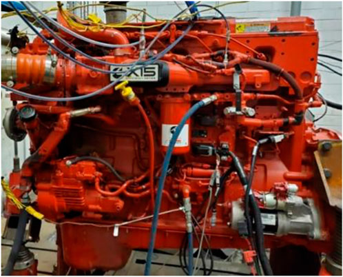
Figure 1. Cummins X15 engine platform installed in the test cell.
The engine is expected to run mainly in two different operating modes, commonly referred to in this work as thermal management (TM) and fuel economy (FE) modes. The authors attributed the transition between these operating modes of the engine to being triggered based on the downstream primary SCR temperature. As the names suggest, the engine runs on the TM mode when the downstream primary SCR temperature is low. During the TM mode, the engine generates more heat leading to low EO NOx and higher fuel consumption and vice versa in the case of the FE mode.
Aftertreatment configurations
The AT system used in this program was a Full Useful Life (FUL) hydrothermally aged system. An accelerated aging protocol (Zavala et al., 2020) was used to age the AT system by thermal exposure to FUL of 435,000 miles, similar to previous works (Harris et al., 2021; Matheaus et al., 2021; Zavala et al., 2022). These aged catalysts are commonly referred to as “Development Aged” end-of-life catalysts (Sharp et al., 2021). These Development Aged catalysts were not exposed to chemical aging such as sulfur and lubricant poisoning.
Figure 2A shows a schematic of the following production-intent AT system in several industry architectures. The AT system consists of a conventional DEF doser, LO-SCR, a Diesel Oxidation Catalyst (DOC), a Diesel Particulate Filter (DPF), and a compact mixer followed by SCR and Ammonia Slip Catalyst (ASC). Generally, such an advanced arrangement for the downstream conventional portion of DOC-DPF-SCR-ASC represents a 2022 production system. This combination of LO-SCR and conventional downstream AT is considered the “baseline” in this demonstration (Meruva et al., 2022). Unlike previous studies that used a heated DEF doser upstream of the LO-SCR (Harris et al., 2021; Matheaus et al., 2021; Sharp et al., 2021; Zavala et al., 2022), this study uses a standard DEF doser in both locations. Catalyst specifications are shown in Table 1.
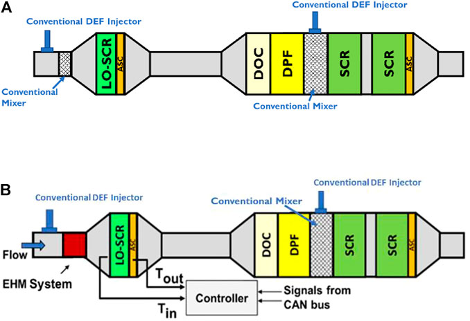
Figure 2. (A) Baseline aftertreatment system architecture with LO-SCR positioned close to the engine. (B) Aftertreatment system architecture with conventional DEF dosers and EHM system.
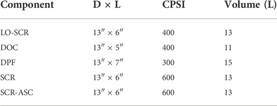
Table 1. Advanced system catalyst specifications.
The focus of this work was to evaluate the addition of an EHM system upstream of the LO-SCR, with the remaining AT being the same as the baseline, as shown in Figure 2B. The actual setup is pictured in Figure 3. In this setup, the conventional mixer upstream of LO-SCR was replaced with the EHM system. The purpose of adding the EHM system was to heat up and maintain the LO-SCR at an optimal temperature for efficient NOx reduction, particularly for rapid heat up during cold start and/or during low-temperature drive cycles.
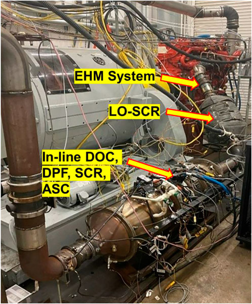
Figure 3. Engine and aftertreatment system, including EHM system and LO-SCR.
EHM system
The EHM system delivers heat to DEF droplets injected in the exhaust pipe, accelerating their conversion to the desired ammonia reductant. It is particularly helpful in lower exhaust temperatures or in low-load cycles while mitigating deposit formation. The EHM system comprises two sections: the EHM and its embedded E-heater. The EHM is the first section of the EHM system, which heats up, enabling DEF injection in exhaust temperatures as low as 130°C. AT system might need additional heat depending on several factors such as engine calibration, cold start, or rapid heat up strategy, AT architecture, system demand or certification target. At these instances, the second section of the EHM system, which is the E-heater, helps in heating the exhaust gas and the downstream catalysts, accelerating catalyst warm-up, especially the SCR catalysts (light-off or primary). The EHM system was positioned upstream of the LO-SCR in this study. In this program, along with the E-heater, the heat generated by the EHM was also leveraged to heat the exhaust gas until the turbo-out temperature reached a certain target, after which the EHM would primarily heat the DEF. During the earlier state, the EHM’s bed temperature would be higher than the latter.
Figures 4A,B show the EHM model and an EHM system model, respectively, each schematically connected to the controller. Figure 4C shows an iso view of a model of the EHM system. The EHM system was designed to operate in 12, 24, or 48 V systems. The demonstration in this work was conducted on a 48 V system, with the first section of the EHM system (Figure 4A) providing 3.8—4 kW and the second section (Figures 4B,C) providing nearly 2 kW, together about 6 kW. Similar to the previous works with E-heaters (Dhanraj et al., 2022; Zavala et al., 2022), the EHM system also contains an E-heater embedded in it. EHM System was used to replace the conventional DEF doser mixer and heated doser as the EHM could heat the DEF with a conventional doser. The swirl plate at the end of the EHM system is used to distribute the flow into the cone upstream of the LO-SCR.
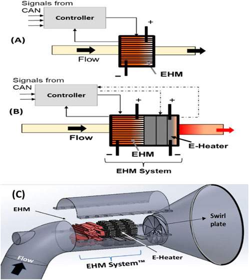
Figure 4. (A) Electrically Heated Mixer (EHM) standalone with its controller. (B) EHM with its embedded E-heater (EHM system) with a controller. (C) Physical depiction of the EHM system.
A control algorithm managed the EHM system for heating the AT system. The controller receives signals from the CAN-bus (e.g., mass flow rate, exhaust temperature, DEF injection rate, and NOx sensor signal). The controller (i.e., in real time) readily manages the EHM system operations to minimize the power consumption while yielding the needed reductant concentration (ammonia), maximizing SCR efficiency, and mitigating deposit formation. In this program, the E-heater was controlled by the Model Based Controller (MBC) and the EHM was controlled by a separate controller.
Figure 5 shows a representative control where the EHM and its embedded E-heater are controlled independently to raise the LO-SCR temperature to 130°C, where DEF can then be injected. Once this is achieved, the power demand reduces. Actual power traces for this work are shown in the test results section. In this example, the E-heater was targeting 130°C at the SCR temperature, and it shuts off once it is achieved. The maximum power capacity of the EHM is 4 kW, and its embedded E-heater is 2 kW.
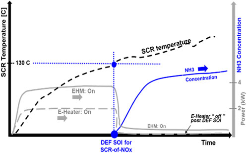
Figure 5. Example of the EHM system operation during a cold start.
EHM system power
The EHM system is powered up by an external power supply in the engine test cell. The power was calculated by recording the voltage and current transmitted to them. This total power was fed to the dynamometer as a parasitic load onto the engine in real time, assuming an 80% generator efficiency consistent with previous works (Matheaus et al., 2021). This additional load was not accounted for in the cycle work, but the emissions resulting from this load were included in the test result analysis. Eq. 1 shows the formula used for this calculation:
Model-based SCR controller
This program used a model-based controller (MBC) for the upstream and downstream SCR catalysts (Sharp et al., 2017; Rao et al., 2020) to control the DEF injection, which is consistent with the baseline work (Meruva et al., 2022). The model tracks ammonia storage in each of the SCR bricks and has a target ammonia storage based on temperature. This work adapted the MBC to control the thermal management strategies to power on the flow heating capabilities of E-heater using the average LO-SCR temperature as the feedback.
Conventional DEF dosers were used during this work. The DEF dosing minimum temperature was set to 180°C throughout the system for the baseline work (Meruva et al., 2022). The EHM system upstream of LO-SCR allowed the DEF dosing to begin at a lower temperature, down to 130°C for the LO-SCR. The primary downstream SCR maintained a 180°C dosing temperature consistent with previous work (Sharp et al., 2021). The DEF dosing trigger temperature was set to the average gas temperature of LO-SCR and the average gas temperature of the first primary SCR for the respective dosing. In this work, a conventional doser coupled with an EHM system was used to replace the heated DEF doser.
Dosing at low temperatures (130°C) can be useful for increasing ammonia storage in the SCR catalyst early in the cycle. It has been demonstrated on both bench testing and engine testing (Masoudi et al., 2022a; Masoudi et al., 2022b) that EHM strongly promotes both ammonia storage and increased SCR NOx conversion efficiency.
With an advantage of better DEF atomization with the EHM system when compared to the baseline, the DEF injection strategy upstream of LO-SCR was modified to be more aggressive at low temperatures and less aggressive at high temperatures, assuming the primary SCR to be hot enough to help with the NOx conversion. This dosing strategy helps reduce NOx at lower temperatures while reducing the risk of ammonia slip from the primary SCR during high exhaust temperature operation.
Emission measurements
Raw exhaust measurements complying with a Code of Federal Regulations Part 1065 were used in this work, which included the following:
• A raw Horiba MEXA 7000 series each for the EO and TP emissions sampling.
• An FTIR for LO-SCR out NOx emission measurements.
The NOx and CO2 measurement variability are ∼ ± 0.001 and ∼ ± 2 g/hp-hr, respectively. This is true for all the test results discussed in this work.
Drive cycles evaluated
This section describes the different drive cycles used to evaluate the performance of the different AT configurations.
Federal Test Procedure
The FTP, a regulatory drive cycle in the United States, was tested, also referred to as the heavy-duty transient cycle, which includes a cold and hot cycle. The CARB 2027 NOx regulatory standard for the FTP drive cycle drops by 90% from 0.2 to 0.02 g/hp-hr (California adopts strong new regulation to further reduce smog-forming pollution from heavy-duty diesel trucks, 2022).
Low Load Cycle
The LLC is a real-world drive cycle consisting of data collected from different applications. This cycle is a new regulatory cycle that is approximately 1.5 h. This cycle focuses on sustained low load, short and long idles, high accelerations after a pronounced cooling period, and low-speed cruise with motoring (MSPROG, 2022). The CARB NOx regulatory limit is at 0.05 g/hp-hr for the year 2027.
Beverage Cycle
The Beverage Cycle is a subset of the LLC. This cycle is derived from a food service delivering truck (MSPROG, 2022). The cycle power is less than the LLC, representing a sustained low load condition. It is only 800 s in length, much shorter than the LLC. As a result, this cycle was repeated four times in succession for thermal conditioning, and the last two cycles were later analyzed for stable results.
Stay Hot Cycle
The Stay Hot Cycle focuses on the AT performance after a prolonged period of cooling by idling the engine for 40 min. This cycle involves operating at a preset speed and load preceding the long idle for thermal conditioning of the engine and the AT system until the temperatures attain a steady state. The test then drops to idle for a 40 min time period where the effect of the AT cooling and NOx reduction can be assessed.
World Harmonized Transient Cycle
The drive cycle named the World Harmonized Transient Cycle (WHTC) is based on the global pattern of heavy-duty commercial vehicle usage. It is a transient engine dynamometer cycle. Both the cold and hot tests for the WHTC are reported.
Test results
This section shows the test results for the baseline advanced AT system compared to the EHM system configurations using the above-mentioned drive cycles. This section shows that a production engine coupled with an AT system integrated with an EHM system upstream of a LO-SCR can meet the CARB NOx regulations for the model year 2027.
FTP composite
Table 2 shows the FTP composite values for the baseline AT along with the added EHM system upstream of the LO-SCR. FTP composite brake-specific emissions are calculated based on 1/7 of the cold test and 6/7 of the hot test. The results reveal that the baseline AT system equipped with the EHM system reduces the composite FTP TP Brake Specific NOx (BSNOx) emission by 3.3-fold (from 0.06 to 0.018) compared with the baseline AT, complying with the NOx regulatory limit of 0.02 g/hp-hr for the year 2027 California regulations, also now in consideration with the US EPA for 2031 and beyond (Summary of EPA proposal, 2022).
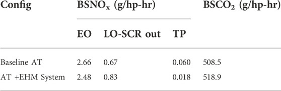
Table 2. FTP Composite test results.
The rise in Brake Specific CO2 (BSCO2) of ∼2% compared with the baseline AT testing is due to the fuel penalty for powering the EHM system. Further optimization is warranted to improve the NOx and CO2 tradeoff.
Cold FTP
Table 3 shows that the AT equipped with the EHM system helps reduce NOx in cold FTP twofold compared with the baseline AT with approximately a 2% fuel penalty. The higher LO-SCR out NOx for the test with EHM system configuration was because of the change in the DEF injection strategy to support better NOx conversion at low-temperature conditions and to reduce the ammonia slip at high-temperature conditions. The EHM system energy consumption was 0.47 kW-hr, which comprises EHM and its embedded E-heater consuming 0.235 and 0.235 kW-hr, respectively. Each element of the EHM system uses the same amount of power on the Cold FTP.
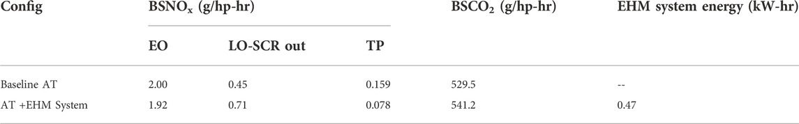
Table 3. Cold FTP test results.
The EHM was set to a maximum of approximately 4 kW, and it tries to heat the exhaust gases until the turbine out temperature is at 200°C. Then, it primarily heats the DEF. Its embedded E-heater was set to a maximum of 2 kW, and it targets the LO-SCR average temperature to reach 235°C. Once the target temperatures were reached, the EHM system was turned off.
Figure 6 shows a graphical comparison of the baseline AT and the AT + EHM system configurations using LO-SCR average temperature, primary SCR inlet temperature, EO NOx, LO-SCR out NOx, TP NOx, the heater power consumption, and BSCO2 as the parameters for the cold FTP cycle.
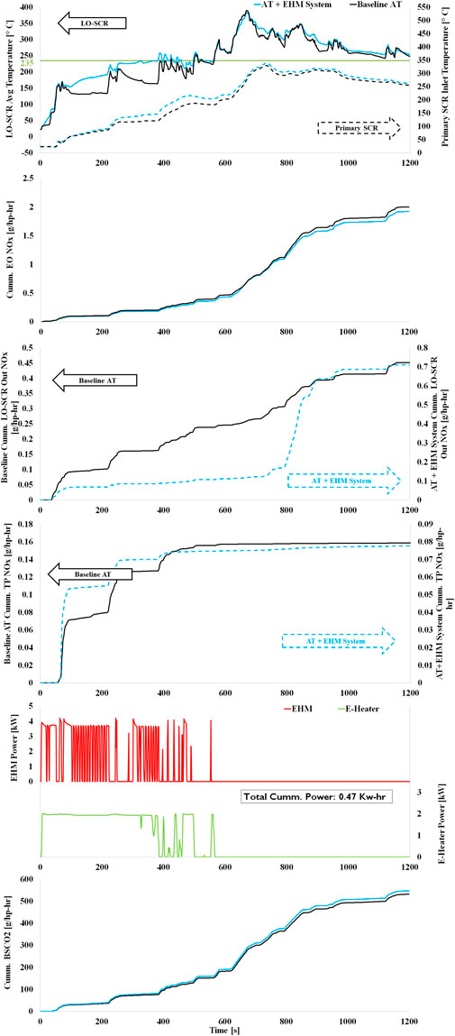
Figure 6. Comparing the baseline AT to the same equipped with the EHM system on a cold FTP cycle for the LO-SCR average temperature, primary SCR inlet temperature, EO NOx, LO-SCR out NOx, TP NOx, heater power consumption, and BSCO2.
As observed from the average LO-SCR temperature plot, the catalyst temperature cools down in the baseline run during an idle event in the baseline configuration, which is avoided with the AT + EHM system configuration. This helps the LO-SCR convert more NOx during the initial 500 s of the cycle by increasing the LO-SCR temperature; however, this also adds to the fuel penalty for powering up the EHM system by about 2%. As mentioned earlier, during 800–1000 s of the cycle, the DEF dosing strategy reduces the DEF injection at the LO-SCR, allowing the primary SCR to convert most of the NOx as the primary SCRs are hot enough to convert NOx at these regions.
Hot FTP
Table 4 shows the numerical comparison of the baseline AT and AT + EHM system configurations for the hot FTP cycle. The EHM system control strategies were the same between the hot FTP and the cold FTP cycles, except that, in the hot FTP cycle, the heating function of the E-heater targeted 225 °C as the LO-SCR average temperature. The table displays that the AT equipped with an EHM system helps drop the TP NOx by almost 5.5-fold (from 0.043 to 0.008) with a fuel penalty of approximately 2%. The EHM system energy consumption for the hot FTP was 0.3 kW-hr, which comprises EHM and its embedded E-heater consuming 0.2 and 0.10 kW-hr, respectively. About two-thirds of the energy is used by the EHM, whereas its embedded E-heater contributes the remaining third. Note that even the hot FTP requires power to the EHM system, which is about 36% less than the cold FTP.
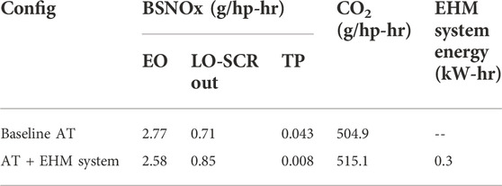
Table 4. Hot FTP test results.
Figure 7 compares the baseline AT and the AT + EHM system configurations using LO-SCR average temperature, primary SCR inlet temperature, EO NOx, LO-SCR out NOx, TP NOx, the heater power consumption, and BSCO2 as the parameters for the hot FTP cycle.
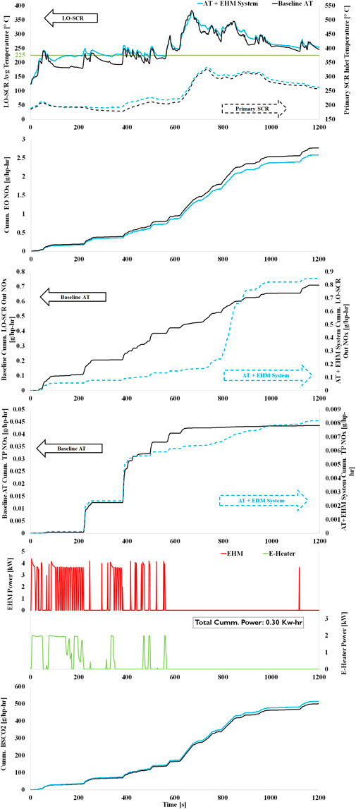
Figure 7. Comparing the baseline AT to the same equipped with the EHM system on a hot FTP cycle for the LO-SCR average temperature, primary SCR inlet temperature, EO NOx, LO-SCR out NOx, TP NOx, heater power consumption, and BSCO2.
The hot FTP test results show that, unlike the baseline configuration, the AT + EHM system configuration sustains the LO-SCR operational temperatures during the idling events until 400 s. This heat at the LO-SCR helps the primary SCR retain the temperature from the previous cycle enabling improved TP NOx conversion performance by more than fourfold or more than 80%. The DEF injection strategy was the same across all the AT + EHM system configuration tests, which explains the lower LO-SCR NOx conversion during 800—1,000 s of the cycle, such as the cold FTP.
Low Load Cycle
Table 5 shows the numerical comparison of the baseline AT and AT + EHM system configurations for the LLC. It reveals the AT + EHM system helps reduce the TP NOx emission by 22-fold, which is a cycle-averaged TP NOx conversion efficiency of 99.3%, relative to 82.5% in the baseline. The EO NOx is higher for the AT + EHM system configuration test as the heat generated from the EHM system is gradually transmitted across the AT system heating the primary SCR, and this enables the engine to run in FE mode. A certain threshold of primary SCR temperature helps the engine stay in FE mode for a longer duration, reducing the CO2 penalty and increasing the EO NOx, but as the EHM system was powered on for most of the test, the overall CO2 penalty was still higher by approximately 5%. The EHM system energy consumption was 4.3 kW-hr, which comprises EHM and its embedded E-heater consuming 3.04 and 1.26 kW-hr, respectively. Approximately 70% of the electrical energy is put into the EHM and the remaining into its embedded E-heater for the LLC.

Table 5. LLC test results.
The heating strategy controlled by the MBC targeted the average LO-SCR temperature based on the inlet temperature of the downstream SCR 1, as shown in Table 6. The EHM control strategy was the same as the FTP cycles, except that it tried to heat the exhaust gas until the turbo-out was at 180°C.
Table 6. Control strategy for the E-heater component in the EHM system for LLC and beverage drive cycles.
Figure 8 compares the LLC between baseline AT and the AT + EHM system configurations. Control parameters are LO-SCR average temperature, primary SCR inlet temperature, EO NOx, LO-SCR out NOx, TP NOx, the heater power consumption, and BSCO2.
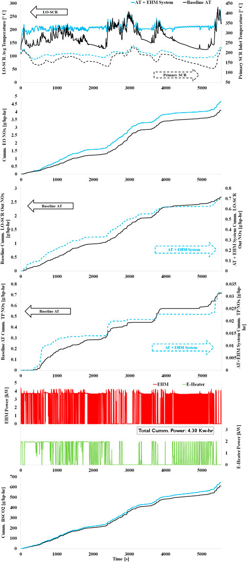
Figure 8. Comparing the baseline AT to the same equipped with the EHM system on an LLC for the LO-SCR average temperature, primary SCR inlet temperature, EO NOx, LO-SCR out NOx, TP NOx, heater power consumption, and BSCO2.
The baseline results show that the LO-SCR was ineffective for most of the cycle in converting the EO NOx due to the extremely low-temperature range. However, with the AT + EHM system configuration, the average LO-SCR temperature was mostly >200°C over the entire cycle, helping it convert NOx even after long idles, which normally cools down the AT system (as it did in the baseline run). Furthermore, in the AT + EHM system, the heat from the upstream catalyst was gradually transferred to the downstream SCR, which helped reduce the TP NOx by 22-fold or an additional ∼96% to a net TP NOx efficiency of 99.3% in this configuration compared to the baseline helping the system to maintain the TP NOx within the California 2027 regulatory limit.
Beverage Cycle
Table 7 shows the numerical comparison of the baseline AT and AT + EHM system configurations for the Beverage Cycle. The EHM system control strategy was the same as the LLC. The AT + EHM system reduces the baseline TP NOx by 38-fold (from 1.669 to 0.044). It produces a cycle-averaged NOx reduction efficiency of 99.2% versus 58.9% in baseline configuration. Similar to the LLC, the engine runs a lot more in the FE mode in the configuration with the EHM system, which explains the drastic difference in the EO NOx values. The EHM system energy consumption was 1.76 kW-hr, which comprises EHM and its embedded E-heater, consuming 1.08 and 0.68 kW-hr, respectively. The EHM requires 62% of the electrical energy, whereas its embedded E-heater uses 38%.
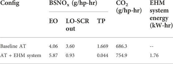
Table 7. Beverage Cycle test results.
Figure 9 compares the Beverage Cycle with baseline AT and the same with EHM system configurations using control parameters LO-SCR average temperature, primary SCR inlet temperature, EO NOx, LO-SCR out NOx, TP NOx, the heater power consumption, and BSCO2.
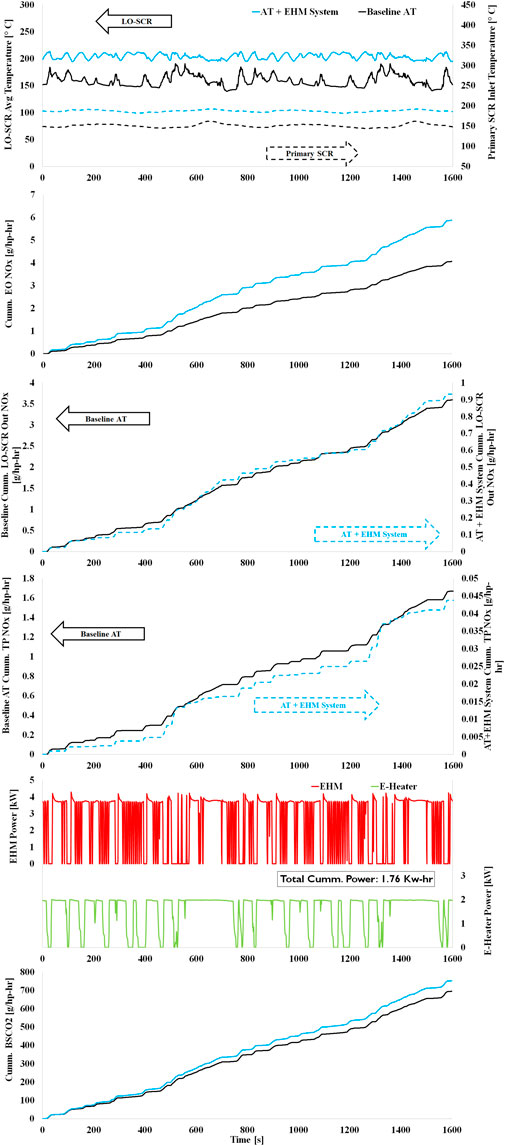
Figure 9. Comparing the baseline AT to the same equipped with the EHM system on a Beverage Cycle for the LO-SCR average temperature, primary SCR inlet temperature, EO NOx, LO-SCR out NOx, TP NOx, heater power consumption, and BSCO2.
The LO-SCR NOx conversion increases in the AT + EHM system configuration compared to baseline by maintaining the temperature above 200°C for most of the cycle. This heat transferred onto the downstream SCR helped in the overall reduction in TP NOx compared to baseline. Though the Beverage Cycle is not a regulatory cycle, the TP NOx emission values were within 0.05 g/hp-hr with the AT + EHM system configuration, even with an increased EO NOx. The net fuel penalty for powering the EHM system was approximately 10%. The primary SCR temperature shown in Figure 9 is the inlet gas temperature. The actual catalyst bed temperature is expected to be a little hotter, which might help reduce the outlet NOx from the LO-SCR.
Stay Hot Cycle
Table 8 shows the numerical comparison of the baseline AT and AT + EHM system configurations for the Stay Hot Cycle. The cycle used the EHM to provide extra heat to the system. This reduced fuel penalty, relying solely on the EHM to heat the AT system. The EHM control strategy is the same as that described in the LLC. As observed in Table 8, the AT + EHM system configuration reduces the TP NOx by almost eightfold (from 0.238 to 0.031) with a fuel penalty of approximately 5%. The EHM system energy consumption was 1.30 kW-hr, which was consumed completely by the EHM as its embedded E-heater was turned off during this cycle.
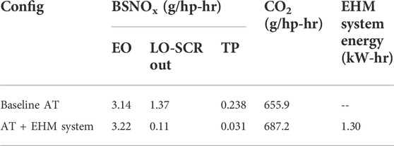
Table 8. Stay Hot test results.
Figure 10 compares the baseline AT and the AT + EHM system configurations using LO-SCR average temperature, primary SCR inlet temperature, EO NOx, LO-SCR out NOx, TP NOx, the heater power consumption, and BSCO2 as the parameters for the Stay Hot Cycle.
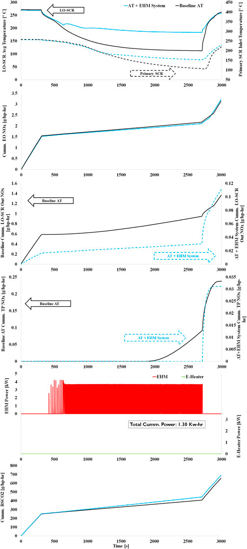
Figure 10. Comparing the baseline AT to the same equipped with the EHM system on a Stay Hot Cycle for the LO-SCR average temperature, EO NOx, LO-SCR out NOx, TP NOx, heater power consumption, and BSCO2.
Though the EHM is mostly advantageous for converting DEF to reductants, it was used in this Stay Hot Cycle to provide enough heat to retain the LO-SCR temperature for long durations to keep the NOx conversion active, which does not happen in the case of the baseline, as the LO-SCR temperature drops down to ∼120°C where it likely cannot respond to any incoming EO NOx.
World Harmonized Transient Cycle
The WHTC Composite is provided first, followed by details on the WHTC cold and then the hot cycles.
WHTC Composite
The WHTC Composite brake-specific emissions are calculated based on 14% of the cold test and 86% of the hot test. Table 9 shows the WHTC composite values comparison of the baseline AT and AT + EHM system configurations. The results show that compared to baseline, the AT + EHM system configuration reduces the transient TP NOx emissions from 0.142 to 0.014 g/kW-hr or by 10-fold. This is 32-fold below the EURO-VI NOx regulatory limit of 0.46 g/kW-hr (0.34 g/hp-hr). The fuel penalty for powering up the EHM system is only about 0.5% relative to the baseline.

Table 9. WHTC Composite test results.
Cold WHTC
Table 10 shows the numerical comparison of the baseline AT and AT + EHM system configurations for the cold WHTC. The EHM system control strategies are exactly like the cold FTP cycle. The results show that both LO-SCR out NOx and the TP NOx dropped by almost threefold relative to baseline compared to the AT + EHM system configuration. The increase in the EO NOx in the AT + EHM system configuration test might be because the engine might have switched to the FE mode at an earlier state than the baseline after the start of the engine as the AT temperatures had risen faster when the EHM system was turned on. The EHM system energy consumption was 0.80 kW-hr, which comprises EHM and its embedded E-heater, consuming 0.48 and 0.32 kW-hr, respectively. Approximately 60% of the electrical heating occurred in the EHM.
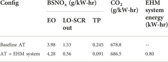
Table 10. Cold WHTC test results.
Figure 11 compares the baseline AT and the AT + EHM system configurations using LO-SCR average temperature, primary SCR inlet temperature, EO NOx, LO-SCR out NOx, TP NOx, the heater power consumption, and BSCO2 as the parameters for the cold WHTC. Adding heat during the cold start for NOx reduction is advantageous as the baseline LO-SCR is too cold to convert NOx for the first 400 s of the cycle. As observed in Figure 11, after 100 s, the AT starts to convert more NOx at the LO-SCR when it is equipped with the EHM system compared to the baseline configuration, which in turn helps reduce the overall TP NOx emissions by ∼ 63%. The overall NOx reduction efficiency with the AT + EHM system configuration for this cold cycle was 98%, with a 1% fuel penalty.
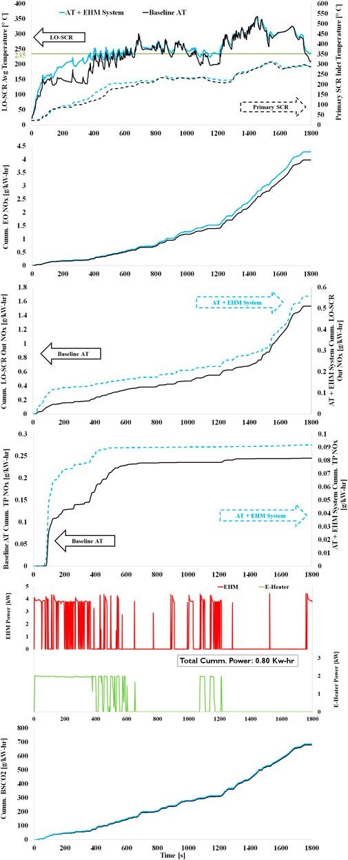
Figure 11. Comparing the baseline AT to the same equipped with the EHM system on a cold WHTC for the LO-SCR average temperature, primary SCR inlet temperature, EO NOx, LO-SCR out NOx, TP NOx, heater power consumption, and BSCO2.
Hot WHTC
Table 11 shows the numerical comparison of the baseline AT and AT + EHM system configurations for the hot WHTC. As observed, LO-SCR NOx out dropped by an additional threefold using the AT configuration equipped with the EHM system relative to the baseline and TP NOx by 125-fold. The EHM system control strategies are exactly like those described for the hot FTP cycle. The EHM system energy consumption was 0.57 kW-hr, which comprises of EHM and its embedded E-heater consuming 0.42 and 0.15 kW-hr, respectively. The EHM system uses 74% of the electrical energy for the EHM and 26% for its embedded E-heater.
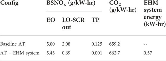
Table 11. Hot WHTC test results.
Figure 12 compares the baseline AT and the AT + EHM system configurations using LO-SCR average temperature, primary SCR inlet temperature, EO NOx, LO-SCR out NOx, TP NOx, the heater power consumption, and BSCO2 as the parameters for the hot WHTC.
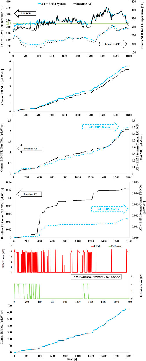
Figure 12. Comparing the baseline AT to the same equipped with the EHM system on a hot WHTC for the LO-SCR average temperature, primary SCR inlet temperature, EO NOx, LO-SCR out NOx, TP NOx, heater power consumption, and BSCO2.
Figure 12 reveals a drastic difference observed in the TP NOx values between the baseline and the AT equipped with EHM system configurations. Similar to the hot FTP cycle, the downstream primary SCR does not lose the thermal heat from the previous cycle in the AT + EHM system configuration as the exhaust gases are heated up before reaching the primary SCR helping achieve a near zero TP NOx on a hot WHTC with less than 1% fuel penalty. The low fuel penalty is because the engine was running more on the FE mode due to the AT temperatures, increasing the EO NOx and compensating the fuel penalty for powering the EHM system.
Summary of results
An EHM system added to a LO-SCR and conventional AT system was investigated on a 15 L heavy-duty diesel engine. The technology has a flexible control strategy embedded in a microcontroller (supplied by Emissol), providing ample opportunities for DEF injection well below 200°C in low-temperature operations and prolonged low-load cycles. In the study performed here, the EHM system was used on a hydrothermally aged Full Useful Life-aged catalyst AT system for optimal system NOx conversion, targeting to meet future NOx emission regulations, including California 2027 (0.02 g/hp-hr tailpipe NOx).
Tables 12 and 13 show the summary of all the test results for both the baseline AT and the AT + EHM system configurations during this work. Results with AT equipped with EHM system along with LO-SCR indicate the following:
• TP NOx in the FTP cycle was reduced by 3.3-fold (to 0.018 g/hp-hr) compared to the baseline, meeting CARB 2027 target.
• Likewise, TP NOx in LLC was reduced by 22.4-fold.
• In Beverage Cycle, TP NOx was reduced by 38-fold.
• In the Stay Hot cycle, TP NOx was reduced by 7.7-fold.
• TP NOx in WHTC was reduced by 10-fold to 0.014 g/kW-hr, likely meeting the upcoming EURO VII limit, which is expected to be ∼0.03–0.05 g/kW-hr (ICCT Comments and Technical Recommendations on Future Euro-7/VII Emission Standard, 2021).
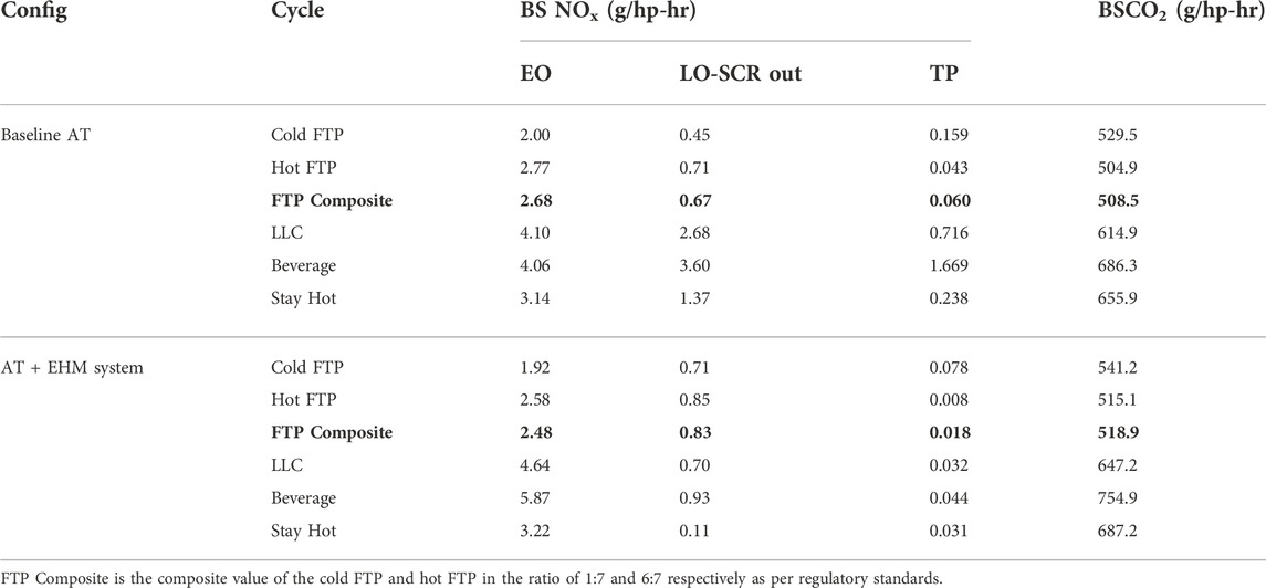
Table 12. Test results summary of drive cycles.
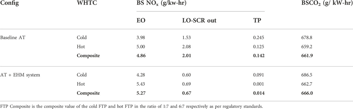
Table 13. Test results summary of European Regulatory Test Cycle WHTC.
Engine optimization/calibration was not performed in this study. Therefore, the observed results could be optimized via further calibration explorations, such as work to reduce the CO2 penalty. The production engine used in this work currently switches between different modes based on the primary SCR temperature. In the future, the engine calibration could be modified to also consider the LO-SCR temperature so that the engine can stay in fuel economy mode for a longer duration, helping reduce the fuel penalty. The NOx/CO2 tradeoff could also be improvised by combining additional technology with the engine, such as CDA.
Future work
The current work focused on thermal management of the AT system through external heaters. However, in addition to the EHM system, adding CDA to the engine can help reduce the fuel penalty for powering up the heaters because CDA technology reduces the exhaust flow rate of the engine, allowing the AT to stay hotter for a longer duration without cooling down, which in turn helps achieve higher fuel economy. This has been observed with one of the programs in the past with a CDA engine and an E-heater (Scott Sluder et al., 2005).
Likewise, the fuel penalty observed in some cycles could be alleviated by synergizing CDA and higher EO-NOx with engine-AT calibration optimization, largely unexplored in this study.
Future studies could focus on exploring the following, amongst others:
(i) Impact of the EHM system on deposit mitigation.
ii) More aggressive ammonia storage strategies in sustained low-temperature operations consistently below 200 C as the EHM system can form reductants “on-demand” for improved in-use compliance.
iii) Testing Real Driving Emissions (RDE) cycles for European applications.
iv) Using EHM (or EHM + E-Heater) for primary SCR.
v) Synergy with advanced engine technologies such as CDA.
Data availability statement
The original contributions presented in the study are included in the article/Supplementary Material, further inquiries can be directed to the corresponding author.
Author contributions
All authors were involved with planning the testing and reviewing the results. All authors contributed discussion to the paper, which was led by PM. All authors contributed to the figures. PM compiled the tables. All authors participated in the revision process.
Acknowledgments
The testing at SwRI for the work was funded by Eaton in cooperation with the SwRI team. This material is based on the work supported by the National Science Foundation under Grant no. 1831231. The latter acknowledgment refers solely to EHM™/ EHM system™ development and engineering support from Emissol.
Conflict of interest
PM, AM, and CS were employed by SwRI. JM was employed by the Eaton Corporation. MM, NP, and SN were employed by Emissol LLC.
The authors declare that this study received funding from the Eaton Corporation and Emissol supplied the EHM™/EHM System™ components (including its microcontroller) and engineering support for this investigation. Testing and analyses were performed by the SwRI team. Eaton, Emissol and SwRI were involved in planning the testing, reviewing the results, the writing of this article, and the decision to submit it for publication.
Publisher’s note
All claims expressed in this article are solely those of the authors and do not necessarily represent those of their affiliated organizations, or those of the publisher, the editors, and the reviewers. Any product that may be evaluated in this article, or claim that may be made by its manufacturer, is not guaranteed or endorsed by the publisher.
References
Berndt, C. (2019). An experimental study of A passive nox adsorber (pna) for the reduction of cold start diesel emissions. Houghton, MI: Michigan Technological University. Open Access Master's Thesis.
California adopts strong new regulation to further reduce smog-forming pollution from heavy-duty diesel trucks | California air Resources board, Available at: https://ww2.arb.ca.gov/news/california-adopts-strong-new-regulation-further-reduce-smog-forming-pollution-heavy-duty#:∼:text=The%20new%20standards%20will%20reduce, than%2023%20tons%20per%20day, 2022.
Dhanraj, F., Dahodwala, M., Joshi, S., and Koehler, E. (2022). Evaluation of 48V technologies to meet future CO2 and low NOx emission regulations for Medium heavy-duty diesel engines. SAE Technical Paper 2022-01-0555. doi:10.4271/2022-01-0555
Greenhouse Gas Standards for Medium- and Heavy-Duty Engines and Vehicles | California air Resources board, Available at: https://ww2.arb.ca.gov/our-work/programs/ghg-std-md-hd-eng-veh/about, 2022.
Harris, T., McCarthy, J., Sharp, C., Zavala, B., and Matheaus, A. (2021). Meeting future NOx emissions limits with improved total fuel efficiency”, presented at heavy-duty, on- and off-highway engines 2021 (ATZ). Rostock, Germany.
ICCT Comments and Technical Recommendations on Future Euro-7/VII Emission Standard (2021). Comments and technical Recommendations on future euro-7/VII emission standard. Available at: https://theicct.org/sites/default/files/eu-commission-euro-7-and-VI-may2021.pdf.
Joshi, M. C., Gosala, D. B., Allen, C. M., Vos, K., Van Voorhis, M., Taylor, A., et al. (2017). Reducing diesel engine drive cycle fuel consumption through use of cylinder deactivation to maintain aftertreatment component temperature during idle and low load operating conditions. Front. Mech. Eng. 8. doi:10.3389/fmech.2017.00008
Kasab, J. J., Hadl, K., Raser, B., Sacher, T., and Graf, G. (2021). Close-coupled SCR - an approach to meet ultra-low NOx requirements for heavy-duty diesel engines. presented at the 2021 CLEERS Virtual Workshop, Sept 13th – 17th.
Masoudi, M., Poliakov, N., and Noorfeshan, S. (2022). A new electrically heated mixer (EHM™) for efficient SCR of NOx in low load cycles. Indianapolis, IN, USA. Submitted to COMVEC.
Masoudi, M., Poliakov, N., Noorfeshan, S., Hensel, J., and Tegeler, E. (2022). A heated AdBlue/DEF mixer for high efficiency NOx reduction in low temperature drive cycles, RDE and city driving. Brussels, Belgium: To appear in Topics in Catalysis. Submitted to CAPoC-12 conference, 29-31 August.
Matheaus, A., Neely, G. A., Sharp, C. A., Hopkins, J., and McCarthy, J. (2021). Fast diesel aftertreatment heat-up using CDA and an electrical heater. SAE 2021-01-0211, April 6.
McCarthy, J., Matheaus, A., Zavala, B., and Sharp, C. (2022). Meeting future NOX emissions over various cycles using a fuel burner and conventional aftertreatment system. SAE Technical Paper 2022-01-0539. doi:10.4271/2022-01-0539
Meruva, P., Matheaus, A., Zavala, B., Sharp, C., and McCarthy, J. (2022). Model based controller for advanced aftertreatment. SAE International Journal of Commercial Vehicles. expected to publish in.
Milovanovic, N., Hamalian, S., Lewander, M., and Larson, K. (2016). The novel 599 SCR and PNA exhaust gas after treatment systems for diesel passenger cars. doi:10.1007/978-3-658-13255-2_4
MSPROG (2022). Hdlownox files workgroup. Available at: https://ww2.arb.ca.gov/sites/default/files/classic/msprog/hdlownox/files/workgroup_20190123/02-llc_ws01232019-1.pdf.
Ramesh, A. K., Gosala, D. B., Allen, C. M., Joshi, M. C., Shaver, G. M., McCarthy, J., et al. (2018). Cylinder deactivation for increased engine efficiency and aftertreatment thermal management in diesel engines, 3. SAE 2018-01-0384, Apr.
Rao, S., Sarlashkar, J., Rengarajan, S., and Sharp, C. (2020). A controls overview on achieving ultra-low NOx. SAE Technical Paper 2020-01-1404. doi:10.4271/2020-01-1404
Scott Sluder, C., Storey, J., Lewis, S., and Lewis, L. (2005). Low temperature urea decomposition and SCR performance. SAE Technical Paper 2005-01-1858. doi:10.4271/2005-01-1858
Sharp, C., Neely, G., Zavala, B., and Rao, S. (2021). CARB low NOX stage 3 program - final results and summary. SAE 2021-01-0589. doi:10.4271/2021-01-0589
Sharp, C., Webb, C., Neely, G., Sarlashkar, J., Rengarajan, S. B., Yoon, S., et al. (2017). Achieving ultra low NOx emissions levels with a 2017 heavy-duty on-highway TC diesel engine and an advanced technology emissions system - NOX management strategies. SAE Int. J. Engines 10 (4), 1736–1748. doi:10.4271/2017-01-0958
Summary of EPA proposal (2022). Heavy-duty clean trucks plan - mobility notes. Available at: https://mobilitynotes.com/summary-of-epa-proposal-heavy-duty-clean-trucks-plan/.
Zavala, Bryan, McCarthy, J., Matheaus, A., and Sharp, C. (2022). Fast diesel aftertreatment heat-up using CDA and an electrical heater between 1.2 and 5.0 kW. Front. Mech. Eng. expected publication date in 2022.
Keywords: heated mixer, advanced aftertreatment, reduced NOx emissions, electric heater, increase exhaust temperature, 130°C DEF injection
Citation: Meruva P, Matheaus A, Sharp CA, McCarthy JE Jr, Masoudi M, Poliakov N and Noorfeshan S (2022) Meeting future NOX emission regulations by adding an electrically heated mixer. Front. Mech. Eng 8:991579. doi: 10.3389/fmech.2022.991579
Received: 11 July 2022; Accepted: 02 August 2022;
Published: 17 October 2022.
Edited by:
Jinlong Liu, Zhejiang University, ChinaReviewed by:
Ruomiao Yang, Zhejiang Chinese Medical University, ChinaWanhui Zhao, Civil Aviation University of China, China
Juan Ou, Xihua University, China
Ziming Yan, Clemson University, United States
Copyright © 2022 Meruva, Matheaus, Sharp, McCarthy, Masoudi, Poliakov and Noorfeshan. This is an open-access article distributed under the terms of the Creative Commons Attribution License (CC BY). The use, distribution or reproduction in other forums is permitted, provided the original author(s) and the copyright owner(s) are credited and that the original publication in this journal is cited, in accordance with accepted academic practice. No use, distribution or reproduction is permitted which does not comply with these terms.
*Correspondence: M. Masoudi, bWFuc291ci5tYXNvdWRpQGVtaXNzb2wuY29t