 Atul Harmukh
 Abhilash Singh1
 S. G. Ganpule
- 1Department of Mechanical and Industrial Engineering, Indian Institute of Technology Roorkee, Roorkee, India
- 2Terminal Ballistic Research Laboratory, Defence Research and Development Organisation, Chandigarh, India
- 3Department of Design, Indian Institute of Technology Roorkee, Roorkee, India
Behind helmet blunt trauma is a significant health concern in modern warfare. The ballistic response of the human head under ballistic impact is highly sought. Towards this end, we conducted ballistic experiments on three different headforms. The following headforms were considered: a) National Institute of Justice based rigid headform, b) Hybrid-III based flexible headform, and c) head model based headform. Headforms b, c were assembled with the Hybrid-III neck. An advanced combat helmet was fitted to the headforms. Helmet-head assembly was subjected to a 9 mm × 19 mm full metal jacket projectile having velocities of 430 ± 15 m/s. The response of the head surrogate in the front, back, side, and crown orientations was studied. Back face deformation (BFD), head kinematics, and intracranial pressures in headforms were measured. In addition, equivalent stress and maximum principal strain in the brain were obtained using concurrent finite element simulations. Results suggest that both local (i.e., due to the localized crushing of the helmet) and global (i.e., due to the bulk motion of the helmet-head parenchyma) responses were dominant under investigated ballistic impacts. Further, the type of the headform affected the biomechanical response. As compared to the rigid headform, a statistically significant increase in head kinematics was observed with the flexible headforms; changes in BFD were statistically insignificant. The orientation dependent responses have been observed. Overall, these results provide novel insights regarding the ballistic response of the headforms with the combat helmet and underscore critical considerations during the ballistic evaluation of helmets.
1 Introduction
Protection against ballistic impact is vital in the design and development of military helmets and armor (Hamouda et al., 2012; Kulkarni et al., 2013; Feli and Jafari, 2017; Mortlock, 2018; Han et al., 2020; Hu et al., 2022; Li et al., 2022; Pinkos et al., 2022; Khodaei et al., 2023). Over the years, combat helmets have undergone significant modifications (Hamouda et al., 2012; Kulkarni et al., 2013; Mortlock, 2018; Hu et al., 2022; Li et al., 2022). In order to improve comfort and protection, cushion foam pads have been added. For better ballistic protection, the outer shell has been upgraded from metal to Kevlar. Due to the progress made in helmet design, some of the existing military helmets are generally capable of stopping the bullet within the helmet and do not perforate the helmet shell (Mortlock, 2018; Li et al., 2022), offering protection from lethal ballistic injuries. Despite this progress, behind helmet blunt trauma (BHBT), resulting from non-penetrating ballistic impact is a significant concern (Sarron et al., 2000; Hisley et al., 2011; Rafaels et al., 2015). In a non-penetrating ballistic impact, considerable kinetic energy is transferred to the helmet-head parenchyma due to the retardation of the bullet in a considerably limited space. This in turn can cause traumatic injuries to the head and the brain (Sarron et al., 2000; Sarron et al., 2004; Raymond et al., 2008; Liu et al., 2012; Freitas et al., 2014; Rafaels et al., 2015; Weisenbach et al., 2018; Li et al., 2023a). Investigations in post-mortem human subjects have reported skull fractures (Sarron et al., 2004; Freitas et al., 2014; Rafaels et al., 2015; Li et al., 2023a), brain contusions (Sarron et al., 2004; Rafaels et al., 2015; Li et al., 2023a), and injurious intracranial pressures (ICPs) (Sarron et al., 2004; Liu et al., 2012; Freitas et al., 2014) due to the non-penetrating ballistic impact.
The interaction of the bullet with the helmet-head parenchyma is characterized by three major dynamic events (Supplementary Figure S1) (National Research Council, 2012) with typical timescales marked in the bracket. a) localized crushing of the helmet due to the bullet impact (<0.5 ms) resulting in local back face deformation (BFD) of the helmet b) bulk motion of the helmet-head parenchyma (0.5–15 ms) resulting in the acceleration of the helmet and the head c) neck reaction due to the bullet impact (1–50 ms). Evaluating the ballistic performance of the helmet against each of these events is vital for overall performance.
To evaluate the military helmets for ballistic performance, several ballistic standards (National Institute of Justice, 1981; H.P. White Laboratory Inc., 1995; VPAM, 2010; National Research Council, 2012; NME, 2013), Table 1, are available and military helmets are generally evaluated using one or more of these standards. These standards specify a headform (consisting of head and neck) made up of a stiff material (e.g., magnesium or aluminum alloy) with infilled witness material (Table 1). A neck is an integral part of the headform and made of the same material as the head. For non-penetrating ballistic impact the stiff material of the headform makes the headform nearly rigid, barring the deformation of infilled witness material.
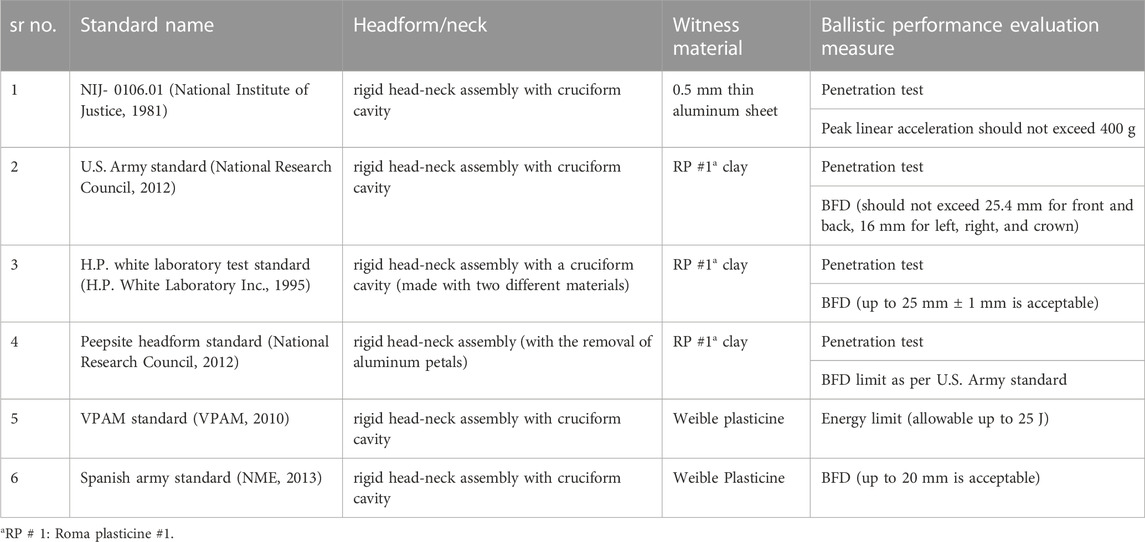
TABLE 1. Summary of the existing standards for the ballistic performance evaluation of the helmets.
For ballistic evaluation, the helmeted headform is mounted on the base. The bullet is fired onto the helmeted headform with the desired velocity. The evaluation of military helmets for ballistic performance is based on two main criteria a) perforation of the helmet shell by the bullet (National Institute of Justice, 1981; H.P. White Laboratory Inc., 1995; National Research Council, 2012; Crouch and Eu, 2017) and b) BFD of the helmet (National Research Council, 2012; NME, 2013; National Research Council, 2014; Crouch and Eu, 2017). None of these standards consider acceleration of the head as a metric for the evaluation of the ballistic performance of military helmets.
Several studies have evaluated the performance of ballistic helmets in terms of penetration resistance of helmet shells and BFD (Tham et al., 2008; Rodríguez-Millán et al., 2016; Miranda-Vicario et al., 2018; Palta et al., 2018). They found BFD values in the range of 4–16 mm. However, a direct correlation between BFD and head/brain injuries could not be established. Even though the aforementioned protocols for helmet evaluation against ballistic impact are routinely used, their robustness in evaluating the risk of BHBT is not known. The use of rigid or semirigid headform, rigid neck, and suitability of infill witness material as a head/brain substitute are a few of the testing protocol-related concerns. Further, it is unclear if the ballistic performance evaluation measures of perforation and BFD are sufficient to holistically evaluate mild and moderate injuries arising from the BHBT.
It is well known in the blunt impact literature (e.g., (Margulies et al., 1990; Rowson et al., 2012a; Kleiven, 2013; Wright et al., 2013; Ji et al., 2014; Zhao and Ji, 2016; Hernandez et al., 2019)) that acceleration and ICP of the head play an important role in causing mild and moderate brain injuries. However, data regarding head acceleration, ICP, and associated injuries is sparse in ballistic impact literature. Freitas et al. (2014) measured the head acceleration and ICP in a head surrogate, equipped with US Marine Corps helmet, during ballistic impact. They reported peak linear head acceleration and peak ICP of 500g and 120 kPa, respectively. Tan et al. (2012) measured the head acceleration on the Hybrid III head equipped with ballistic helmet. They found the head acceleration in the range of 150–400 g. In a recent study, Rodriguez-Millan et al. (2023) measured the considerable head acceleration (∼400 g), and neck motion in the Hybrid III headform. These data suggest that the head acceleration is a potential critical consideration during ballistic impact, especially for mild and moderate injuries. These investigations are encouraging, however, one-to-one tcomparison between BFD and associated head response (i.e., acceleration, ICP) is not available.
The goal of the present work was to examine the effect of the type of the headform on the biomechanical response of the head during ballistic impact. Towards this end ballistic response of a helmeted head for three different headforms, namely,: a) headform I: rigid headform, b) headform II: flexible headform, and c) headform III: a head model based headform was investigated. The headform I had an integrated rigid neck whereas the headform II and III were mounted on the Hybrid-III neck. The biomechanical response is evaluated in terms of BFD, head acceleration, ICPs, stresses, and strains. This information was used to comment on critical aspects during the ballistic evaluation of helmets.
Compared to the existing literature, the work is novel in several aspects: a) we holistically evaluate the ballistic performance of helmets in terms of BFD, head acceleration, brain and brain simulant pressures, and brain strains. The work provides new insights (detailed in results and discussion sections) based on these evaluations. b) To the best of our knowledge, we are the first to measure and quantify angular kinematics during ballistic impact. We demonstrate that the head undergoes considerable angular motion during ballistic impact. c) Using novel experiments and concurrent computational simulations, we provide detailed mechanistic understanding of the choice of headform on the biomechanical response of the head.
The manuscript is organized as follows. In the methods section, the details of the headforms, ballistic helmet, experimental setup, including universal weapon mounting systems, and ballistic testing have been described. In the result section, the mechanical responses of the headforms in terms of peak head accelerations, and BFD has been presented. For the headform III, brain simulant response is also presented in terms of ICP and brain strains (from the concurrent simulation). The effect of headform orientation and trauma mitigation pads is investigated. In the next section, results are discussed, with respect to existing literature, in the context of ballistic testing of helmets, measured mechanical parameters, and their significance in ballistic evaluation. The key findings are summarized in the conclusion section.
2 Methods
2.1 Drop test of witness material
Before conducting ballistic impact attenuation tests, it was necessary to cure the witness material and perform the drop tests on the witness material to ensure that the witness material was appropriately cured. This aspect was important in the subsequent measurement of BFD. To facilitate this, drop tests were conducted on the 400 mm × 400 mm x150 mm block of witness material (Supplementary Figure S2). In this work, Roma Plasticine No. 1 (i.e., R.P. #1) clay was used as a witness material. In the literature, R.P. #1 clay (Metker et al., 1975; Prather et al., 1977) is most widely used as a witness material to evaluate the performance of armor in terms of back face signature in ballistic testing. Prior to the drop tests, the texture of the clay was calibrated according to the National Institute of Justice (NIJ) standard (National Institute of Justice, 2008) by maintaining the clay at 35°C. The drop tests were conducted as per NIJ-0101.06 (National Institute of Justice, 2008). A steel ball of diameter 63.5 mm and mass of 1.04 kg was fixed to the electromagnet and dropped from a height of 2 m on the block of the clay. Five drop tests were performed, and the depth of indent in the clay was measured with the help of a depth gauge. It was ensured that the distance between indent locations was at least 77 mm to avoid boundary effects affecting the response. We found that the average indentation depth in the clay was within the specified range of 19 ± 2 mm as per NIJ-0101.06 standard (National Institute of Justice, 2008).
2.2 Headforms
Ballistic experiments on three headforms were conducted. The headform I was a rigid headform with a rigid neck, as shown in Figure 1A. The geometry of the headform I was based on NIJ-0106.01 standard (National Institute of Justice, 1981). The lower portion of the headform (including the neck) was made up of aluminum alloy (E = ∼69 GPa, ν = ∼0.31) (Naimon et al., 1975), and the upper portion was made up of nylon-66 (E = ∼2.7 GPa, ν = ∼0.42) (Yu et al., 2004). The headform had a cruciform cavity that was filled with witness material (i.e., R.P. # 1 clay (Prather et al., 1977)) before the ballistic tests. The mass of the headform I was 9.2 kg, including the rigid neck and the witness material. The headform II (Figure 1B) was a relatively flexible headform fully made of nylon-66. The geometry of the headform II was based on the Hybrid-III head. However, the geometry of the headform II was modified to accommodate a cruciform cavity (based on the NIJ-0106.01 standard (National Institute of Justice, 1981)). The headform was assembled with the Hybrid-III neck (Humanetics, Farmington Hills, MI). The mass of the headform II was 5.5 kg including the Hybrid-III neck and the witness material. In headforms I, II, top portion was made up of same material (i.e., nylon-66 (Yu et al., 2004)). This was done to ensure that the interaction of the helmet with the witness material and resulting BFD were not affected by different contact conditions arising due to the different materials.
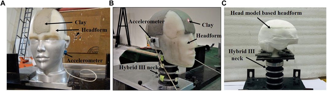
FIGURE 1. Photographs of headforms: (A) Headform I: rigid headform (B) Headform II: flexible headform (C) Headform III: a head model based headform (skin is not shown for the clarity of photograph).
The headform III consisted of a head model based head. The geometry of the headform III (Figure 1C) was based on the Global Human Body Models Consortium’s (GHBMC) 50th percentile male (Gayzik et al., 2011a; Mao et al., 2013). The GHBMC head were 3D printed, as described below. The headform III was mounted on the Hybrid-III neck. Note that 3D printing of facial features of GHBMC head and GHBMC neck was not possible due to the complex anatomy. The mass of the headform III was 4.8 kg, including the Hybrid-III neck.
The skin simulant (i.e., silicone with a shore hardness of 30A (Chanda et al., 2017; Dragon Skin)) of headform III was prepared from the 3D-printed skin mold. The skull simulant (i.e., nylon-66 (Yu et al., 2004)) was 3D printed. The brain simulant was prepared by mixing parts A and B of Sylgard-527 (ρ = 975 kg/m3, G = 1.5 kPa) (Zhang et al., 2006; Fontenier et al., 2016) in 1:1 proportion by weight. Brain simulant was poured into the cavity of the skull. Thermoplastic polyurethane (TPU) with an elastic modulus of ∼20 MPa mimicked the dura mater. The dura mater of thickness ∼2 mm was 3D printed. The skull and dura were 3D printed together using a bimaterial printer.
While selecting surrogate materials (skin, skull, brain, and dura mater) for the headforms, we attempted to match the densities and elastic/shear moduli of the head constituents with the corresponding human head counterparts (Mao et al., 2013). These two properties are critical for mimicking the dynamic response. Hence, these criteria were used while selecting surrogate materials. For the skull simulant (i.e., nylon-66 (Yu et al., 2004)), strength properties were also similar to the human skull properties (Falland-Cheung et al., 2017). Supplementary Table S1 tabulates the material properties of head constituents and corresponding surrogate material properties reported in the literature (Barber et al., 1970; McElhaney et al., 1970; Yu et al., 2004; Zhang et al., 2006; Groves et al., 2013; Budday et al., 2017; Falland-Cheung et al., 2017; Smith et al., 2020; Walsh et al., 2021). For the loading considered, there was no fracture or breakage of any of the headform material. Additional details regarding the preparation of head surrogates for headform III are available in Singh et al. (Singh et al., 2022).
2.3 Ballistic helmet
The medium-sized advanced combat helmet (ACH) was used in this work. ACH is designed for the ballistic threat level of IIIA (National Institute of Justice, 1985). The ACH helmet (Figure 2) consisted of Kevlar helmet shell of thickness 10 mm made up of Kevlar (K-29 with 16 layers), seven trauma mitigation foam pads of thickness 16 mm each made up of foam, and a chin strap. The helmet contained 1.5 mm thick protective plate (steel) at the end of Kevlar layers (i.e., just prior to the inner surface of the helmet shell), Figure 2C. The helmet mass was 1.29 kg. The standoff distance (i.e., the distance between the inner layer of the helmet shell and the outer layer of the head surface) was 16 ± 1 mm.
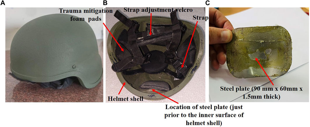
FIGURE 2. Photograph of Advanced Combat Helmet: (A) exterior view depicting a Kevlar shell (B) interior padding system showing a crown pad and 6 peripheral pads. (C) steel plate.
2.4 Experimental setup
The ballistic testing was carried out by using the Universal weapon mounting system (M.S. Instruments PLC ORPINGTON, BRS 48Q, U.K.). The Universal weapon mounting system (Figure 3) consisted of the firing pin, hammer, barrel holding chamber, adjustable valve, and barrel. This work used a barrel with an internal diameter of 9 mm. The system works on the momentum conservation principle, and chemical energy is converted to kinetic energy. On triggering, the hammer hits the firing pin, and then the firing pin hits the primer of the bullet, which causes the burning of the gunpowder and produces high-pressure gases pushing the bullet. This results in the ejection of the bullet from the barrel at a high velocity. In this system, different velocities can be achieved by changing the barrel length and the type of projectile used. This work used the 9 mm × 19 mm full metal jacket (FMJ) bullet. The mass of the bullet was 8 g. To measure the velocity of the bullet, the chronograph was placed at a distance of 2.5 m from the barrel end. It consisted of two optical-based sensors at the entry and exit. The velocity of the bullet was estimated from the time taken to traverse the entry and exit locations.
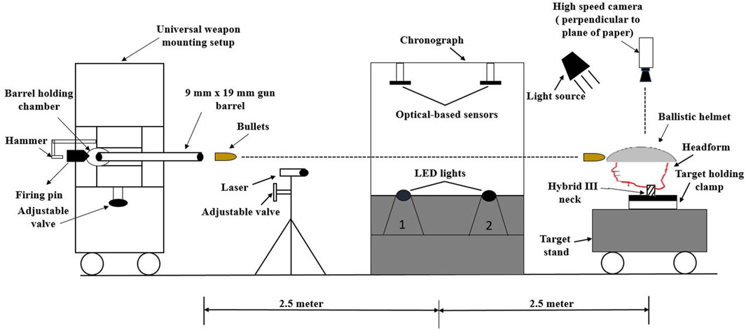
FIGURE 3. Schematic of universal weapon mounting system.
The target (i.e., headform) was clamped to the target stand located at a distance of 5 m from the barrel end. In this target stand, a 360° movable target holding clamp (both in the vertical and horizontal direction) was used to fix and rotate the headforms in front, back, left, right, and crown orientations, respectively. As described earlier, the headform cruciform cavity (for the headforms I and II) was filled with curated R.P. # 1 clay, and the helmet was adequately secured on the headform using a chin strap. Note that in the crown position, the bullet trajectory was coaxial with the vertical axis of the head and the Hybrid III neck. Before the ballistic testing, each helmet was physically checked for weight, manufacturing defects, or damage. After each bullet impact, the helmet was removed, and BFD was measured using a digital depth gauge.
The linear acceleration and angular velocity of the headform were measured using a triaxial linear accelerometer (Endevco® 7268C, range: ±2000 g, PCB Piezotronics, Depew, NY) and triaxial angular rate sensor (ARS3 PRO, range ±8,000 Deg/s, Diversified Technical System, Seal Beach, CA), respectively. The accelerometers were mounted on the left side of the head (below the ear) using double-sided tape (Figure 1). Angular accelerations were calculated by differentiating the angular velocity data using the forward difference method.
For headform III, in addition to the head acceleration, intracranial pressures (ICPs) were measured using piezoelectric pressure sensors (Kulite-HKS-375, range: ± 500 psi, Sensol Inc.). Note that the term ICP used here has a different connotation than the term “ICP” used in clinical practice. In the classical experiments, Nahum et al. (1977) measured the pressures in the brains of post-mortem human subjects at five different locations. He called these pressures ‘intracranial pressures (ICPs)’ as they were measured inside the cranium. Since then, this connotation has been routinely used for the measurement of brain pressure in the head injury biomechanics community (e.g., (Nahum et al., 1977; Liu et al., 2012; Skotak et al., 2013; Freitas et al., 2014; Du et al., 2022; Li et al., 2023b),), to the point it has become a standard terminology. Further, the ICP sensors were mounted in the anterior and posterior locations (Figure 4). Two 20 mm diameter holes were specified on the back surface of the skull during 3D printing. The pressure sensors were inserted in the brain simulant through each of these holes using two hollow aluminum pipes; the pipes had negligible weight. Piezoelectric ICP sensors are classically mounted in the brain tissue using pipes. This is a fairly standard practice that has been widely used (e.g., (Nahum et al., 1977; Nusholtz et al., 1984; Skotak et al., 2013; Feng et al., 2016; Shin et al., 2019)). Since these types of sensors are reasonably rigid, hence some arrangement is required to guide the sensors. The sensor probe was adequately aligned with the tip of the pipe, and it was ensured that the sensing surface was fully exposed to the brain simulant. After alignment, the sensor was tightened within the groove of the pipe to avoid relative motion (if any) between the pipe and the sensor. For the front and right orientations, two separate headforms were used, and sensors were pointed in front and right directions, respectively. The Slice Nano data acquisition system (Diversified Technical Systems, Inc., Seal Beach, CA) was used to acquire the head kinematics and ICP data at a sampling rate of 20,000 Hz with an antialiasing filter of 4000 Hz. During post-processing, signals were filtered using the channel filter class (CFC) 180.
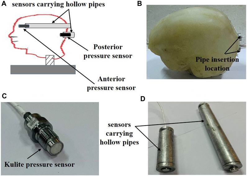
FIGURE 4. (A) schematic depicting the pressure sensor locations within the brain simulant (B) photograph of the headform III after inserting the pressure sensors (C) photograph of Kulite pressure sensor (D) sensors carrying hollow pipes.
In this work, for each of the headforms I and II, 10 helmets with pads and 5 helmets without pads were used. Ballistic testing was carried out in five orientations: front, back, left, right, and crown. For the headform III, 10 helmets with pads were used, and the ballistic testing was done in front and right orientations. Thus, the data presented in this work is based on a total of 170 ballistic experiments. Note that for the Headform III, we did not perform the experiments in back, and crown orientations due to the difficulty in mounting the ICP sensors. Left orientation was also not considered due to the left-right symmetry. Hence, the experiments with headform III were chosen judiciously.
For the without pad configuration, the experiments were conducted in the front, back, left, right, and crown orientations. For the front, back, left, and right orientations, the crown pad was not removed in order to maintain a consistent fit of the helmet on the headform. The presence of crown pad ensured the same stand-off distance at the front, back, and side orientations and proper helmet mounting on the headform. For the crown orientation, the crown pad was removed. So, the consistency in fitting was less definitive. However, since the head and neck were horizontal in this orientation, the helmet fitting effect on the head may not be a critical consideration.
2.5 Data analysis
From the measured acceleration-time histories, peak resultant linear acceleration, peak resultant angular velocity, and peak resultant angular acceleration were obtained for each headform and for each test configuration. In addition, head injury criteria (HIC) and brain injury criteria (BrIC) were estimated from Eqs 1 and 2, respectively. The HIC estimates the risk of head injury based on the resultant linear acceleration, whereas BrIC estimates the risk of brain injury based on the angular velocity. The HIC (Eq. 1) was calculated using the resultant linear acceleration-time histories measured on the headform.
where a(t) is the resultant linear acceleration at the C.G. of the head. t1 and t2 are time intervals between which HIC is calculated.
where wx, wy, and wz are measured peak angular velocities and wxc, wyc, and wzc are critical values of angular velocities in the x, y, and z directions, respectively. The values of critical angular velocities (wxc = 66.25 rad/s, wyc = 56.45 rad/s, and wzc = 42.87 rad/s) proposed by Takhounts et al. (2013) were used. Additional details of HIC can be found in Wilde et al. (2019), Mariotti et al. (2019), and BrIC in Takhounts et al. (2013), respectively. BFD was also measured for headforms I, II. For headform III, intracranial pressures were measured.
Experimental data were presented as mean ± standard deviation. An unpaired, two-tailed Student’s t-test with unequal variance was performed to assess statistical significance between various cases, and p-values of <0.05 were considered statistically significant.
2.6 Concurrent computational simulations
Concurrent computational simulations were performed to investigate brain biomechanical response, especially to compute stress and strain values. This work used the finite element human body model developed by the Global Human Body Models Consortium (GHBMC) in a standing position (Gayzik et al., 2011a; Gayzik et al., 2011b). The full-body human model, including the head model (Mao et al., 2013), has been extensively validated in the past under blunt impact loading through multi-institutional effort (Mao et al., 2013; Schoell et al., 2015; Arun et al., 2016; Devane et al., 2019; Perez-Rapela et al., 2019).
The head model (Mao et al., 2013), Figure 5, consisted of the scalp, skull, facial bones, sinuses, dura, pia, arachnoid, falx, tentorium, bridging veins, and brain. The brain was segmented into the cerebrum, cerebellum, ventricles, brainstem, thalamus, corpus callosum, and basal ganglia. The cerebrum was further segmented into white and gray matter. The model was meshed using 270,552 elements. Most of the head components were meshed using 8-noded hexahedral elements. The outer and inner skull were modeled as elastic-plastic, whereas the brain, scalp, and facial tissue were modeled as linear, viscoelastic. The rest of the components were modeled as a linear, elastic material. Supplementary Table S2 tabulates the material properties of GHBMC head model.
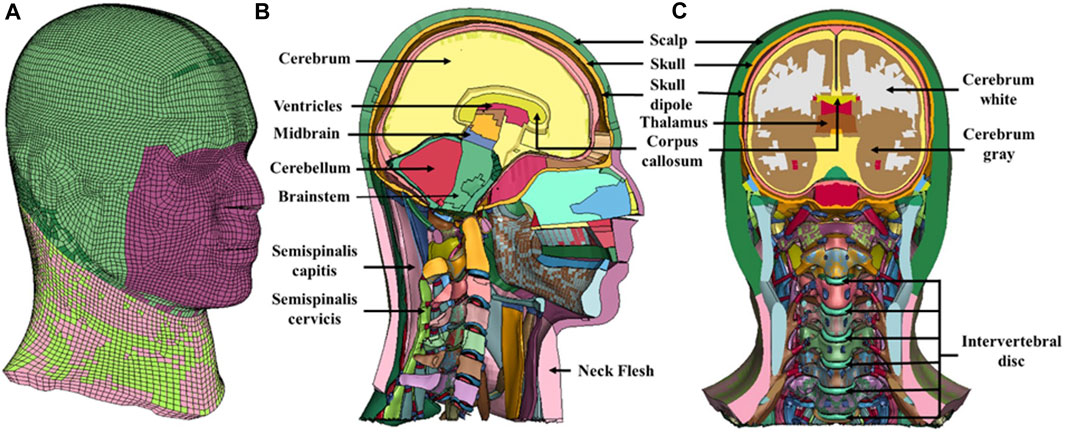
FIGURE 5. Computational head model used in this investigation. (A) isometric view (B) midsagittal view (C) midcoronal view.
Experimentally measured head kinematics (i.e., acceleration-time histories) for the headform III was used as an input to the simulations. Supplementary Figure S3 shows the acceleration-time curve, which was used as an input for the simulation. In the head model, the skull has three components: outer skull, skull dipole, and inner skull. Acceleration-time histories as an input can only be applied to rigid components/materials. Hence, to facilitate this, skull dipole was made rigid and acceleration-time histories were applied to the CG of the skull dipole. Kinematic coupling was used between the CG of the skull dipole and the rest of the nodes of the skull dipole. The skull-brain interface was modeled as tied. Since we were mainly interested in brain response (as opposed to the helmet damage response), explicitly modeling the interaction of the bullet with helmet-head parenchyma was not required. Specifying the experimentally measured head kinematics serves the purpose of the objectives of this work. Further, this approach also saves computational costs.
The simulations were carried out for front and right impact orientations. Each simulation was performed for 40 ms, and it was ensured that the peak values of stresses (ICP, von Mises stress) and strain (MPS) were established. ICP-time histories from the simulations were compared against ICP data from the experiments.
2.7 Parametric investigations for different headform masses and stiffness
Additional computational simulations using GHBMC head model were performed to study the sensitivity of mass and stiffness of the head on the brain biomechanical response. In this work, the mass of headform I (9.2 kg, including neck) was significantly larger than the masses of headforms II (5.5 kg, including neck) and III (4.8 kg, including neck). In the first case, for comparing the biomechanical response with different head masses, the GHBMC head mass was scaled from 4.5 kg to 9 kg by increasing the skull’s density (hence mass). Note that in the experiments, the overall size of the three headforms is approximately similar. Hence, changing the density to increase the mass is reasonable. In another case, the GHBMC head mass was scaled from 4.5 kg to 9 kg by increasing the brain’s density (hence mass). We note that the case with changing the skull mass in the simulations is closer to the experiments of this work, as the skull surrogate mass is changing in headforms I, II, and III. In these simulations, experimentally measured head kinematics (i.e., acceleration-time histories) for the headform III was used as an input for both the cases.
Further, to compare the different head stiffness, we changed the skull material to aluminum and Nylon-66. By changing the skull material to aluminum and Nylon-66, the mass of the GHBMC head was changed to 4.62 kg and 4.08 kg, respectively.
3 Results
3.1 Bullet velocities
Bullet velocities were calculated using the chronograph. Bullet velocities of 430 ± 15 m/s were obtained. These velocities correspond to a ballistic threat level of IIIA (National Institute of Justice, 1985).
3.2 Mechanical response of headforms
Figure 6 and Table 2 show the mechanical response for headforms I-III. The peak values of various mechanical parameters are depicted for each impact orientation. Compared to the headform I, we observed a statistically significant increase (p < 0.05) in the linear acceleration, angular velocity, angular acceleration, HIC, and BrIC values for headforms II and III, for all orientations. BFD values between headforms I and II were statistically insignificant (p > 0.05) except for the crown orientation.
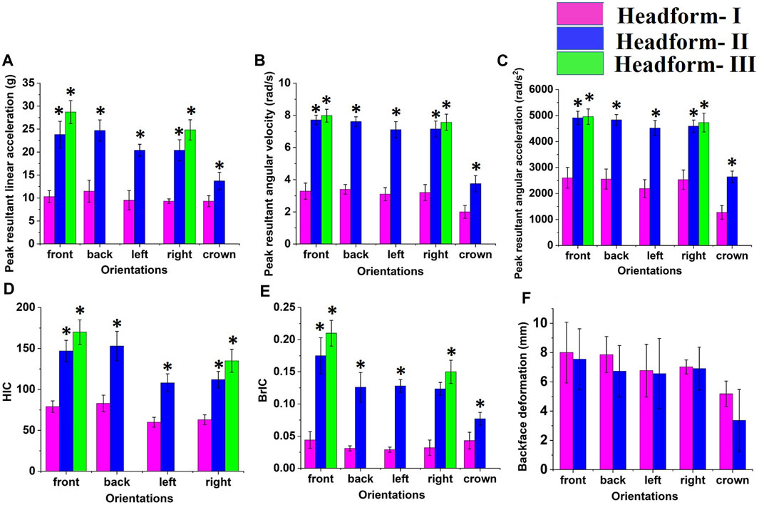
FIGURE 6. Mechanical response of headforms I, II, and III against ballistic impact: (A) peak resultant linear acceleration (B) peak resultant angular velocity (C) peak resultant angular acceleration (D) HIC (E) BrIC (F) BFD. * indicates the statistically significant changes, p < 0.05.
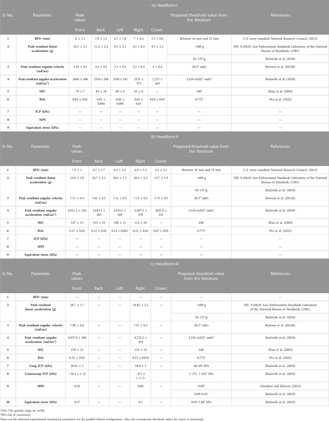
TABLE 2. Peak values of various biomechanical parameters obtained on the headforms due to the ballistic impact. Headforms were equipped with the ACH helmet having a Kevlar shell and trauma mitigation pads.
In headform II, peak values of linear acceleration, angular velocity, and angular acceleration were increased by ∼50% (average of all orientations), ∼55%, and ∼50%, respectively, compared to headform I. HIC and BrIC values were increased by ∼45% and 70%, respectively. Note that the HIC value for crown orientation was not estimated due to the poor signal quality. In contrast, BFD was decreased by ∼10% in all orientations.
In headform III, peak values of linear acceleration, angular velocity, and angular acceleration were increased by ∼63% (average of the front and right side orientation), ∼60%, and ∼50%, respectively, as compared to headform I. HIC and BrIC values were increased by ∼53% and ∼66%, respectively. The mechanical responses between headform II and III were marginally changed (within <10%), and the differences were statistically insignificant (p > 0.05).
3.3 Effect of impact orientation on the mechanical response of headform
We also investigated the effect of impact orientation on the mechanical response of the headforms (Figure 6). Statistically insignificant (p > 0.05) differences in the peak values of linear acceleration, angular velocity, angular acceleration, BFD, HIC, and BrIC were observed between various orientations, except for the crown orientation.
The linear acceleration, angular velocity, and angular acceleration responses for the front and back orientation were similar, with differences of <5% in the mechanical response. Compared to front and back orientation, these responses decreased in the lateral (i.e., left, right) orientations. With respect to the front orientation, linear acceleration, angular velocity, and angular acceleration were decreased by ∼15%, ∼8%, and ∼12%, respectively, in the lateral orientations. The HIC and BrIC values were also decreased in the lateral orientation compared to the front and back orientation. Among all orientations, kinematic responses were the least for the crown orientation. BFD values were maximum for the front orientation, followed by back, lateral, and crown orientations.
3.4 Mechanical response of the headforms with and without trauma mitigation pads
Figure 7 shows the mechanical response of the headform II, with and without trauma mitigation pads. Statistically insignificant (p > 0.05) differences in peak values of linear acceleration, angular velocity, angular acceleration, HIC, and BrIC were observed between these configurations for all orientations. In contrast, a statistically significant (p < 0.05) increase in BFD values was seen for the without pad configuration.
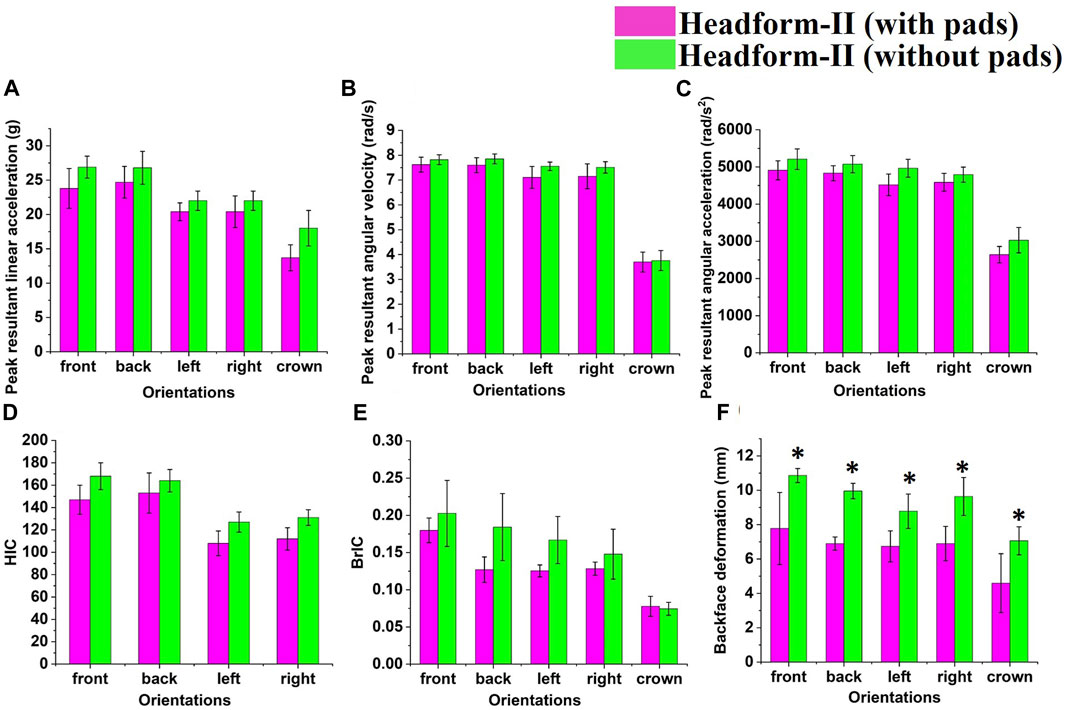
FIGURE 7. Mechanical response of the headform II with and without trauma mitigation pads: (A) peak resultant linear acceleration (B) peak resultant angular velocity (C) peak resultant angular acceleration (D) HIC (E) BrIC (F) BFD. * indicates the statistically significant changes, p < 0.05.
For the without pad configuration, peak values of linear acceleration, angular velocity, angular acceleration, and BFD values were increased by ∼17% (average of all orientations), ∼8%, ∼7%, and ∼42%, respectively, as compared to the with pad configuration. Further, HIC and BrIC values also increased by ∼18% and ∼24%, respectively. A similar trend with and without trauma mitigation pads has been observed for the headform I.
3.5 Measurement of ICPs
Figure 8 shows the experimentally measured ICP values for the headform III. A response from concurrent computational simulation is also shown. A coup-contrecoup pattern in ICP response was observed at the anterior and posterior locations, respectively. Peak positive ICP value of ∼20–25 kPa and positive phase duration of ∼2–3 ms have been observed at the anterior location. Peak negative ICP value of ∼8–10 kPa and negative phase duration of ∼3–4 ms have been observed at the posterior location. A reasonable agreement was seen between the computed and experimentally measured ICPs in terms of temporal evolution (Figure 8) and CORA scores (Table 3).
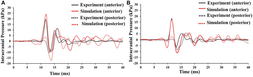
FIGURE 8. Experimentally measured ICPs (shown in black) in the Headform III, and ICPs obtained from the computational simulation (shown in red). (A) front orientation (B) right orientation. The starting 7 ms time was idle time (due to the triggering, triggering was earlier). Time t = 0 did not represent the time when bullet hits the helmet.
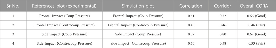
TABLE 3. CORA scores between the computational and experimentally measured ICPs.
The ICPs are mainly governed by the bulk modulus of the brain and are typically insensitive to the geometric complexities (e.g., (Teferra et al., 2018; Li et al., 2021)). The bulk modulus of the brain used in the computational head model (2.1 GPa (Mao et al., 2013)) and the bulk modulus of the brain simulant (i.e., Sylgard-527) used in the experiments (∼1.1 GPa (Zhang et al., 2009)) were on the order of GPa. Thus, in this work, the computational simulation and experiments showed a reasonable agreement in the ICP plots, despite the lack of geometric complexity of the computational head model in the simplified experimental headform (i.e., headform III).
3.6 Estimation of strains and stresses from the computational head model
The computational head model validated against experimental ICP response (Figure 8) was used to investigate the spatiotemporal evolution (Figure 9) of biomechanical quantities such as ICP, equivalent (von Mises) stress, and maximum principal strain (MPS). The spatiotemporal evolution of ICP, equivalent stress, and MPS was played out within ∼30 ms. Peak ICP, equivalent stress, and MPS of ∼25 kPa, ∼0.4 kPa, and ∼0.10, respectively, were observed.
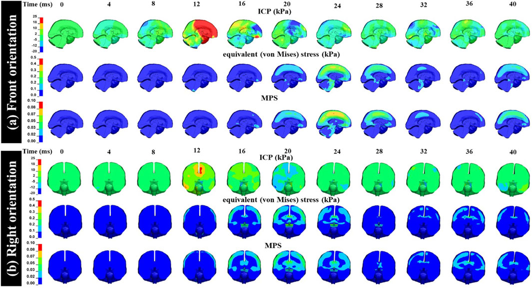
FIGURE 9. Spatiotemporal evolution of ICP, equivalent (von Mises) stress, and MPS obtained from the computational simulation. The model simulation range for the ICP is −20–25 kPa, fringe range for the equivalent stress is 0–0.5 kPa, and fringe range for the MPS is 0–0.10. (A) front orientation (B) right orientation.
3.7 Effect of mass and stiffness of the head on brain biomechanical response
Figure 10 shows the mechanical response in terms of ICP, von Mises stress, and MPS for different head masses. We observed that the ICP, von Mises stress, and MPS were marginally changed (within 2%) when the head mass was increased from 4.5 kg to 9 kg by increasing the skull’s density. Furthermore, when the head mass was increased from 4.5 kg to 9 kg by increasing the brain’s density, the ICP, von Mises stress, and MPS were significantly increased. The ICP was increased from 25 kPa to 140 kPa, von Mises stress was increased from 0.3 kPa to 0.9 kPa, and MPS was increased from 0.08 to 0.27.
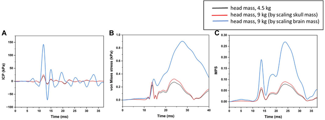
FIGURE 10. Sensitivity of brain response to the head mass (A) ICP (B) von Mises stress (C) MPS.
In addition to scaling the mass of head, the stiffness of the head was also changed. We changed the skull material to aluminum and Nylon-66. We did not find significant differences (Figure 11) in the brain’s biomechanical response (ICP, von Mises stress, and MPS).
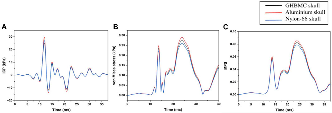
FIGURE 11. Sensitivity of brain response to the stiffness of the skull (A) ICP (B) von Mises stress (C) MPS.
4 Discussion
In this work, the biomechanical response of the head surrogates under the ballistic impact (bullet velocities 430 ± 15 m/s) has been investigated. Results suggest that the type of headform affects the biomechanical response. As compared to the rigid headform (headform I), a statistically significant increase (p < 0.05) in the head kinematics was observed with the flexible headforms (headforms II, III), Figure 6 and Table 2. Changes in BFD were statistically insignificant (p > 0.05), as BFD is a measure of local deformation at the impact site. Further, considerable resultant angular velocity (7–8 rad/s) and resultant angular acceleration (4000–5000 rad/s2) have been observed with the flexible headforms (Table 2; Figure 6). The mechanical responses between headform II and III were marginally changed (within <10%), and the differences were statistically insignificant (p > 0.05). The geometry of the headform II was based on the Hybrid-III head, whereas the geometry and head constituents of the headform III were based on the GHBMC head. Note that for the headform II, Hybrid-III head based geometry was chosen as it is simpler to manufacture and can be easily integrated with Hybrid-III neck. Differences in measured mechanical parameters between headforms II and III were statistically insignificant. Hence, the choice of headform II can be attractive as a potential headform for the futuristic laboratory evaluation of ballistic helmets. The 3D printing of the facial features, bimaterial 3D printing of the skull and dura, and the preparation of the skin and brain simulants of the headform III are cumbersome and challenging.
Our results suggest that both local (i.e., due to the localized crushing of the helmet) and global (i.e., due to the bulk motion of the helmet-head parenchyma) responses were dominant under the investigated ballistic impact. Thus, futuristic testing protocol and standards should adequately consider the biofidelic or reasonably realistic headform. Further, the evaluation of ballistic helmets using bullet perforation and BFD as only parameters may not be sufficient to evaluate the risk of BHBT. Additional quantities such as linear acceleration, angular velocity, and angular acceleration should be measured. Further, HIC and BrIC values should be computed from these measurements. If possible, these experimental measurements should be complemented with concurrent computational modeling to further investigate brain biomechanical response, especially to compute strains and stresses in various brain regions. Computational simulations provide an attractive alternative, provided they are robust.
The findings reported in this work are consistent with the finding in the literature. The BFD values obtained for headforms I and II (Table 2 a, b; Figure 6) are consistent with BFD values obtained in various computational and experimental investigations (Li et al., 2015; Rodríguez-Millán et al., 2016; Miranda-Vicario et al., 2018; Palta et al., 2018; Cai et al., 2020). Rodríguez-Millán et al. (2016), using experiments and computational modeling, studied the response of rigid headform with witness material (i.e., R.P. # 1) equipped with the ACH helmet against ballistic impact (9 mm FMJ bullet with a velocity of 425 ± 15 m/s). They obtained BFD value in the range of 9–12 mm in the witness material for front, back, left, and right and crown orientations. Using a computational model of ACH mounted on the rigid headform, Palta et al. (2018) reported BFD of 10–15 mm in the witness material for front, back, left, and right orientations for the 9 mm FMJ bullet with a velocity of 370 m/sec. In a similar study, Li et al. (2015) obtained a BFD of 11–16 mm in the clay for a bullet velocity of 370 m/s. Miranda-Vicario et al. (2018) experimentally investigated the response of the U.S. army headform with Weible Plasticine clay as a witness material. They obtained the BFD of 8–12 mm for front and back orientations and 4–6 mm for left and right orientations using the 9 mm FMJ bullet with a velocity of 300–380 m/sec. Cai et al. (2020) measured BFD in ACH equipped computational head model using a 9 mm bullet with a velocity of 400–460 m/sec. They found the BFD values 10–13 mm in front, back, left, right, and crown orientation. Even though these BFD measurements are encouraging, the direct correlation of BFD with the injury is lacking. Rafaels et al. (2015) studied the response of helmeted heads of post-mortem human subjects (PMHS) under non-perforating ballistic impact with velocities of 400–460 m/sec. They observed skull fractures, bruising of the dura, and severe local skin friction injuries due to the deformation of the helmet. However, the amount of BFD could not be quantified due to the use of PMHS. These findings suggest that efforts should be made to establish a relation between BFD and head, brain injuries.
We measured linear and angular kinematics and associated injury matrices (HIC and BrIC) for the headforms I, II, and III (Table 2; Figure 6). Due to the larger mass and rigid neck, the peak values of linear acceleration, angular velocity, and angular acceleration of the headform I were lower (∼45–60%) than the headforms II and III. In headforms II and III, we obtained a peak resultant linear acceleration of ∼20–29 g, peak resultant angular velocity of 7–8 rad/s, and peak resultant angular acceleration of 4000–5000 rad/s2. Aare and Kleiven (2007) studied the ballistic response of a computational head model with the Personal Armour System Ground Troops suspension (i.e., no pads) helmet against a 9 mm FMJ bullet for a velocity of 360 m/sec. The helmet shell was composed of either Aramide laminate or Titanium. Various helmet configurations with shell thickness, mass, and material properties were investigated. They obtained peak linear and angular accelerations of ∼80–138 g and ∼2,100–3,800 rad/s2, respectively. Jazi et al. (2014), using a computational model of the ACH helmet and the human head, obtained linear head acceleration in the range of 23–115 g. They observed that linear head acceleration was sensitive to the properties of the foam pad, especially the stiffness and strength of the foam. A less stiff pad was more efficient in absorbing the impact energy and reducing the acceleration of the head. Li et al. (2016) made similar observations regarding foam pad stiffness. Tse et al. (2014), using a computational model of the ACH helmet and human head, have reported a peak linear acceleration of ∼15–50 g for the ACH helmet. The linear and angular accelerations obtained in this work are generally commensurate with the aforementioned findings from the literature. Some of the quantitative differences can be attributed to the differences in helmet configuration (e.g., shell material, number of shell layers considered, properties of the foam pads, presence of steel plate in the current work) and lack of neck in computational investigations in the literature.
In this work, orientation-dependent biomechanical responses have been observed, with front orientation being the most severe (Figure 6). Higher peak values of various biomechanical parameters in the frontal orientation are attributed to the larger curvature, relatively smaller surface area, relatively smaller standoff distance between the interior of the helmet shell and the headform. This observation is consistent with the finding in the literature (Tan et al., 2012; Pasquali and Gaudenzi, 2017; Palta et al., 2018; Cai et al., 2020). Palta et al. (2018) observed the orientation-dependent BFD response in a computational model of ACH mounted on the rigid headform. BFD was highest for the front orientation, followed by back, left, and right orientations. They attributed the orientation-dependent response to the standoff distance, a curvature of the impact location, and the distance of the impact location from the edge of the helmet. Pasquali and Gaudenzi (2017) investigated the curvature effect on the impact resistance of woven fiber composite targets and observed that the curved surface of woven fabric composite has low ballistic resistance compared to the flat surface. Using a computational model of the ACH helmet and human head, Cai et al. (2020) obtained the maximum BFD in the front orientation.
Investigation with and without trauma mitigation pads revealed that the BFD values were significantly increased (by ∼42%) in the absence of pads (Figure 7). This can be attributed to the pads locally absorbing the impact energy resulting in lower BFD. Head kinematics and associated quantities (HIC, BrIC) were increased by ∼20%. However, this increase was statistically insignificant (p > 0.05). Li et al. (2016), using the computational model of the ACH helmet mounted on the human head, observed an increase in HIC (∼23%) in the absence of pads.
The helmet pads used in this study were mainly used for comfort and were not specifically designed for energy absorption. This may have an influence on obtained insignificant differences in head kinematics with and without pads. We also observed localized crushing of the pads, generating an indent in the Roma plasticine clay. This local deformation response may also have attributed to insignificant changes in the (global) acceleration profiles.
Computational simulations suggested that considerable ICP (20–25 kPa), equivalent stress (0.3–0.4 kPa), and MPS (0.08–0.10) were generated in the brain (Figures 8, 9, Table 2). The ICP, stress, and strain pattern were heterogenous, and evolution has a timescale of ∼30 ms. This is consistent with the findings in the literature (Jazi et al., 2014). Jazi et al. (2014) studied the response of the human brain with different densities of foam padding under ballistic impacts. They reported the peak ICP ∼21 kPa with low-density foam padding for a velocity of 360 m/sec. Aare and Kleiven (2007) have reported brain strain of 0.11–0.15 (cortex), 0.05–0.09 (corpus callosum) in a PASGT helmet equipped computational head model subjected to a 9 mm FMJ bullet with a velocity of 360 m/s.
Further, additional simulations were performed to study the sensitivity of head mass and stiffness on the brain biomechanical response. We observed that the brain biomechanical response (i.e., ICP, von Mises stress, and MPS) was not affected by the scaling (increasing/decreasing) of the mass of the skull (Figure 10). This is because the brain mass and contact area between the skull and the brain remain unchanged. It has been shown that the mass of the brain and the contact area between the brain and the skull govern the mechanical fields in the brain (Gibson, 2006; Liu et al., 2017; Ganpule et al., 2020). Further, it was observed that the brain biomechanical response was significantly affected when the mass of the brain was changed (Figure 10). The case with changing the skull mass in the simulations is closer to the experiments of this work, as the skull surrogate mass is changing in headforms I, II, and III. The mass of the clay in headform I, II was ∼2 kg, and mass of the brain stimulant in headform III was ∼1.7 kg.
We also compared the biomechanical response of the head by varying the stiffness of the skull. We changed the material of the skull to aluminum and Nylon-66. We found that there were minimal variations in the brain’s biomechanical response (Figure 11). This could be due to the fact that the brain mass and contact area between the skull and the brain remain unchanged. Note that, in these simulations, the effects due to stress wave propagation were not captured, as the interaction of the bullet with helmet-head parenchyma was not explicitly modeled. Stiffness/compliance of the head may affect the contribution from stress wave propagation. Fully addressing the effect of compliance will require explicit modeling of the interaction of the bullet with helmet-head parenchyma.
4.1 Assessment of peak biomechanical parameters against existing injury thresholds
Table 2 lists the peak values of various biomechanical parameters due to the ballistic impact. Corresponding proposed injury threshold values in the literature are also listed. Most of the proposed injury threshold values (except BFD) correspond to either the 25%–75% quartile range for mild Traumatic Brain Injury (mTBI) or 50% risk of concussion. While selecting the sources (references) for the threshold values, sources having biomechanical data with clinically confirmed concussions in humans were preferred, wherever possible. Based on data tabulated in Table 2, for the investigated helmet configuration, the values of angular acceleration and MPS were above the 25% quartile range. Values of all other parameters (BFD, linear acceleration, angular velocity, HIC, BrIc, ICP, and equivalent stress) were below the corresponding injury thresholds. This data suggests that measuring the aforementioned parameters and evaluating the performance of ballistic helmets against these parameters should be considered.
5 Limitations
This work has a few limitations. In this work, in the simulations, explicit interaction of the bullet with helmet-head parenchyma was not considered. Thus, only effects arising out of the bulk motion of the helmet-head parenchyma (0.5–15 ms) were considered, as this was the major focus of the manuscript. We have neglected effects due to localized crushing of the helmet due to the bullet impact (<0.5 ms), resulting in the local deformation of the helmet. Effects of localized crushing of the helmet can be significant if one is interested in studying BFD due to the localized crushing of the helmet. Crushing may generate additional strains and stresses in the brain or brain simulant, locally, beneath the region of crushing. The local response at the helmet-head (scalp) interface and corresponding stress wave propagation effects will also be missed out by not modeling the interaction of the bullet with helmet-head parenchyma. Wave propagation effects generally contribute to the stresses, especially at early times. The results of explicit modeling of the interaction of the bullet with helmet-head parenchyma will be reported in the future with a focus on BFD and damage of the helmet.
For the headforms considered in this work, C.G. lied inside the head (i.e., in the brain simulant or within the clay). For the experiments, mounting the accelerometer in the brain simulant or the clay was not possible. Hence, we mounted the accelerometer on the left side of the head (below the ear).
6 Conclusion
This work investigated the biomechanical response of the helmeted headforms against ballistic impact. NIJ based rigid headform (headform I), Hybrid-III, and head model based flexible headforms were considered. Five impact orientations (front, back, right, left, crown) were considered. Some of the key findings of the work are:
1) Response of the helmet-head parenchyma was dominated by the localized crushing of the helmet and bulk motion of the head, as indicated by measured BFD and head kinematics values, respectively.
2) For the investigated headforms peak resultant linear acceleration of 10–29 g, peak resultant angular velocity of 3–8 rad/s, and peak resultant angular acceleration of 1,200–5000 rad/s2 were observed.
3) Peak ICP of 20–25 kPa, peak equivalent stress of 0.3–0.4 kPa, and peak MPS of 0.08–0.10 were seen from the concurrent computational simulations.
4) Changes in peak values of the linear acceleration, angular velocity, and angular acceleration were statistically significant between rigid (headform I) and flexible headforms (headforms II, III). BFD values were statistically insignificant between these headforms.
5) The orientation dependent responses have been observed, with front and crown orientations being the most and least severe, respectively.
6) BFD value was significantly increased (by ∼42%) for the helmet without trauma mitigation pads. However, changes in head kinematics were statistically insignificant between with and without pad scenarios.
7) Peak resultant angular acceleration and peak MPS values exceeded the 25th percentile quartile limits proposed for the mTBI.
Taken together, these results provide detailed mechanistic insights into the biomechanical response of headforms during ballistic impact with implications in the evaluation of ballistic helmets.
Data availability statement
The original contributions presented in the study are included in the article/Supplementary Material, further inquiries can be directed to the corresponding author.
Author contributions
AH: Formal Analysis, Investigation, Methodology, Writing–original draft. AS: Formal Analysis, Writing–review and editing. PK: Investigation, Software, Writing–review and editing. SV: Methodology, Project administration, Resources, Writing–review and editing. PK: Project administration, Resources, Writing–review and editing. SG: Conceptualization, Funding acquisition, Methodology, Project administration, Resources, Supervision, Writing–review and editing.
Funding
The author(s) declare financial support was received for the research, authorship, and/or publication of this article. Funding Information Funder- Terminal Ballistic Research Laboratory, DRDO, Chandigarh, India Award Number- TBRL/CARS/110/2021.
Acknowledgments
Authors acknowledge Global Human Body Model Consortium owned GHBMC Model distributed to IIT Roorkee through a license agreement with the Elemance. The authors acknowledge assistance of the staff of the Terminal Ballistic Research Laboratory, Chandigarh in conducting the experiments. We also acknowledge the numerous discussions with Dr. Debarati Bhattacharjee. SG acknowledges the financial support from the Terminal Ballistic Research Laboratory, DRDO, Chandigarh, under the grant TBRL/CARS/110/2021.
Conflict of interest
The authors declare that the research was conducted in the absence of any commercial or financial relationships that could be construed as a potential conflict of interest.
Publisher’s note
All claims expressed in this article are solely those of the authors and do not necessarily represent those of their affiliated organizations, or those of the publisher, the editors and the reviewers. Any product that may be evaluated in this article, or claim that may be made by its manufacturer, is not guaranteed or endorsed by the publisher.
Supplementary material
The Supplementary Material for this article can be found online at: https://www.frontiersin.org/articles/10.3389/fmech.2023.1270905/full#supplementary-material
References
Aare, M., and Kleiven, S. (2007). Evaluation of head response to ballistic helmet impacts using the finite element method. Int. J. impact Eng. 34 (3), 596–608. doi:10.1016/j.ijimpeng.2005.08.001
Arun, M. W., Umale, S., Humm, J. R., Yoganandan, N., Hadagali, P., and Pintar, F. A. (2016). Evaluation of kinematics and injuries to restrained occupants in far-side crashes using full-scale vehicle and human body models. Traffic Inj. Prev. 17 (1), 116–123. doi:10.1080/15389588.2016.1197394
Barber, T. W., Brockway, J. A., and Higgins, L. S. (1970). The density of tissues in and about the head. Acta neurol. Scand. 46 (1), 85–92. doi:10.1111/j.1600-0404.1970.tb05606.x
Beckwith, J. G., Zhao, W., Ji, S., Ajamil, A. G., Bolander, R. P., Chu, J. J., et al. (2018). Estimated brain tissue response following impacts associated with and without diagnosed concussion. Ann. Biomed. Eng. 46 (6), 819–830. doi:10.1007/s10439-018-1999-5
Budday, S., Sommer, G., Birkl, C., Langkammer, C., Haybaeck, J., Kohnert, J., et al. (2017). Mechanical characterization of human brain tissue. Acta biomater. 48, 319–340. doi:10.1016/j.actbio.2016.10.036
Cai, Z., Huang, X., Xia, Y., Li, G., and Fan, Z. (2020). Study on behind helmet blunt trauma caused by high-speed bullet. Appl. bionics biomechanics 2020, 1–12. doi:10.1155/2020/2348064
Chanda, A., Unnikrishnan, V., Flynn, Z., and Lackey, K. (2017). Experimental study on tissue phantoms to understand the effect of injury and suturing on human skin mechanical properties. Proc. Institution Mech. Eng. Part H J. Eng. Med. 231 (1), 80–91. doi:10.1177/0954411916679438
Crouch, I., and Eu, B. (2017). “Ballistic testing methodologies,” in The science of armour materials (Elsevier), 639–673.
Devane, K., Johnson, D., and Gayzik, F. S. (2019). Validation of a simplified human body model in relaxed and braced conditions in low-speed frontal sled tests. Traffic Inj. Prev. 20 (8), 832–837. doi:10.1080/15389588.2019.1655733
Dragon Skin “Dragon Skin™ series addition cure silicone rubber compounds,” in 11 Technical bulletin, smooth on. Available online: https://www.smooth-on.com/productline/dragon-skin/. (Accessed February 15, 2023)
Du, Z., Li, Z., Wang, P., Wang, X., Zhang, J., Zhuang, Z., et al. (2022). Revealing the effect of skull deformation on intracranial pressure variation during the direct interaction between blast wave and surrogate head. Ann. Biomed. Eng. 50 (9), 1038–1052. doi:10.1007/s10439-022-02982-5
Falland-Cheung, L., Waddell, J. N., Chun Li, K., Tong, D., and Brunton, P. (2017). Investigation of the elastic modulus, tensile and flexural strength of five skull simulant materials for impact testing of a forensic skin/skull/brain model. J. Mech. Behav. Biomed. Mater. 68, 303–307. doi:10.1016/j.jmbbm.2017.02.023
Feli, S., and Jafari, S. (2017). Analytical modeling for perforation of foam-composite sandwich panels under high-velocity impact. J. Braz. Soc. Mech. Sci. Eng. 39, 401–412. doi:10.1007/s40430-016-0489-7
Feng, K., Zhang, L., Jin, X., Chen, C., Kallakuri, S., Saif, T., et al. (2016). Biomechanical responses of the brain in swine subject to free-field blasts. Front. neurology 7, 179. doi:10.3389/fneur.2016.00179
Fontenier, B., Hault-Dubrulle, A., Drazetic, P., Fontaine, C., and Naceur, H. (2016). On the mechanical characterization and modeling of polymer gel brain substitute under dynamic rotational loading. J. Mech. Behav. Biomed. Mater. 63, 44–55. doi:10.1016/j.jmbbm.2016.06.008
Freitas, C. J., Mathis, J. T., Scott, N., Bigger, R. P., and MacKiewicz, J. (2014). Dynamic response due to behind helmet blunt trauma measured with a human head surrogate. Int. J. Med. Sci. 11 (5), 409–425. doi:10.7150/ijms.8079
Ganpule, S., Sutar, S., and Shinde, K. (2020). Biomechanical analysis of woodpecker response during pecking using a two-dimensional computational model. Front. Bioeng. Biotechnol. 8, 810. doi:10.3389/fbioe.2020.00810
Gayzik, F., Moreno, D. P., Geer, C. P., Wuertzer, S. D., Martin, R. S., and Stitzel, J. D. (2011a). Development of a full body CAD dataset for computational modeling: a multi-modality approach. Ann. Biomed. Eng. 39 (10), 2568–2583. doi:10.1007/s10439-011-0359-5
Gayzik, F. S., Moreno, D. P., Vavalle, N. A., Rhyne, A. C., and Stitzel, J. D. (2011b). “Development of the global human body models consortium mid-sized male full body model,” in International workshop on human subjects for biomechanical research (Washington, DC, USA: National Highway Traffic Safety Administration).
Gibson, L. (2006). Woodpecker pecking: how woodpeckers avoid brain injury. J. Zoology 270 (3), 462–465. doi:10.1111/j.1469-7998.2006.00166.x
Giordano, C., and Kleiven, S. (2014). Evaluation of axonal strain as a predictor for mild traumatic brain injuries using finite element modeling. Stapp Car Crash J. 58 (14), 29–61. doi:10.4271/2014-22-0002
Groves, R. B., Coulman, S. A., Birchall, J. C., and Evans, S. L. (2013). An anisotropic, hyperelastic model for skin: experimental measurements, finite element modelling and identification of parameters for human and murine skin. J. Mech. Behav. Biomed. Mater. 18, 167–180. doi:10.1016/j.jmbbm.2012.10.021
Hamouda, A., Sohaimi, R., Zaidi, A., and Abdullah, S. (2012). “Materials and design issues for military helmets,” in Advances in military textiles and personal equipment, 103–138.
Han, R., Qu, Y. J., Yan, W. M., Qin, B., Wang, S., and Wang, J. Z. (2020). Experimental study of transient pressure wave in the behind armor blunt trauma induced by different rifle bullets. Def. Technol. 16 (4), 900–909. doi:10.1016/j.dt.2019.11.010
Hernandez, F., Giordano, C., Goubran, M., Parivash, S., Grant, G., Zeineh, M., et al. (2019). Lateral impacts correlate with falx cerebri displacement and corpus callosum trauma in sports-related concussions. Biomechanics Model. Mechanobiol. 18 (3), 631–649. doi:10.1007/s10237-018-01106-0
Hisley, D. M., Gurganus, J. C., and Drysdale, A. W. (2011). Experimental methodology using digital image correlation to assess ballistic helmet blunt trauma. J. Appl. Mech. 78 (5). doi:10.1115/1.4004332
Hu, Q. R., Shen, X., Qian, X., Huang, G., and Yuan, M. (2022). The personal protective equipment (PPE) based on individual combat: a systematic review and trend analysis. Def. Technol. 28 (1), 195–221. doi:10.1016/j.dt.2022.12.007
Jazi, M. S., Rezaei, A., Karami, G., Azarmi, F., and Ziejewski, M. (2014). A computational study of influence of helmet padding materials on the human brain under ballistic impacts. Comput. methods biomechanics Biomed. Eng. 17 (12), 1368–1382. doi:10.1080/10255842.2012.748755
Ji, S., Zhao, W., Li, Z., and McAllister, T. W. (2014). Head impact accelerations for brain strain-related responses in contact sports: a model-based investigation. Biomechanics Model. Mechanobiol. 13 (5), 1121–1136. doi:10.1007/s10237-014-0562-z
Khodaei, M., Safarabadi, M., Haghighi-Yazdi, M., and Farzannia, M. A. (2023). On the ballistic impact behavior of foam-filled honeycomb core/composite skin sandwich panels. J. Braz. Soc. Mech. Sci. Eng. 45 (5), 244. doi:10.1007/s40430-023-04172-3
Kleiven, S. (2013). Why most traumatic brain injuries are not caused by linear acceleration but skull fractures are. Front. Bioeng. Biotechnol. 1, 15. doi:10.3389/fbioe.2013.00015
Kulkarni, S. G., Gao, X. L., Horner, S., Zheng, J., and David, N. (2013). Ballistic helmets–their design, materials, and performance against traumatic brain injury. Compos. Struct. 101, 313–331. doi:10.1016/j.compstruct.2013.02.014
Li, Y., Li, X., and Gao, X.-L. (2015). Modeling of advanced combat helmet under ballistic impact. J. Appl. Mech. 82 (11), 111004. doi:10.1115/1.4031095
Li, X., Gao, X.-L., and Kleiven, S. (2016). Behind helmet blunt trauma induced by ballistic impact: a computational model. Int. J. Impact Eng. 91, 56–67. doi:10.1016/j.ijimpeng.2015.12.010
Li, X., Zhou, Z., and Kleiven, S. (2021). An anatomically detailed and personalizable head injury model: significance of brain and white matter tract morphological variability on strain. Biomechanics Model. Mechanobiol. 20, 403–431. doi:10.1007/s10237-020-01391-8
Li, Y., Fan, H., and Gao, X.-L. (2022). Ballistic helmets: recent advances in materials, protection mechanisms, performance, and head injury mitigation. Compos. Part B Eng. 238, 109890. doi:10.1016/j.compositesb.2022.109890
Li, Y., Adanty, K., Vakiel, P., Ouellet, S., Vette, A. H., Raboud, D., et al. (2023a). Review of mechanisms and research methods for blunt ballistic head injury. J. biomechanical Eng. 145 (1), 010801. doi:10.1115/1.4055289
Li, Y., Vakiel, P., Adanty, K., Ouellet, S., Vette, A. H., Raboud, D., et al. (2023b). Evaluating the intracranial pressure biofidelity and response repeatability of a physical head-brain physical model in frontal impacts. Ann. Biomed. Eng. 51, 1–18. doi:10.1007/s10439-023-03198-x
Liu, H., Kang, J., Chen, J., Li, G., Li, X., and Wang, J. (2012). Intracranial pressure response to non-penetrating ballistic impact: an experimental study using a pig physical head model and live pigs. Int. J. Med. Sci. 9 (8), 655–664. doi:10.7150/ijms.5004
Liu, Y., Qiu, X., Ma, H., Fu, W., and Yu, T. (2017). A study of woodpecker's pecking process and the impact response of its brain. Int. J. Impact Eng. 108, 263–271. doi:10.1016/j.ijimpeng.2017.05.016
Mao, H., Zhang, L., Jiang, B., Genthikatti, V. V., Jin, X., Zhu, F., et al. (2013). Development of a finite element human head model partially validated with thirty five experimental cases. J. biomechanical Eng. 135 (11), 111002. doi:10.1115/1.4025101
Margulies, S. S., Thibault, L. E., and Gennarelli, T. A. (1990). Physical model simulations of brain injury in the primate. J. biomechanics 23 (8), 823–836. doi:10.1016/0021-9290(90)90029-3
Mariotti, G. V., Golfo, S., Nigrelli, V., and Carollo, F. (2019). Head injury criterion: mini review. Am. J. Biomed. Sci. Res. 5 (5), 406–407. doi:10.34297/ajbsr.2019.05.000957
McElhaney, J. H., Fogle, J. L., Melvin, J. W., Haynes, R. R., Roberts, V. L., and Alem, N. M. (1970). Mechanical properties of cranial bone. J. biomechanics 3 (5), 495–511. doi:10.1016/0021-9290(70)90059-x
Metker, L. W., Prather, R. N., and Johnson, E. M. (1975). A method for determining backface signatures of soft body armors. Edgewood Arsenal Aberdeen Proving Ground MD.
Miranda-Vicario, A., Bravo, P., and Coghe, F. (2018). Experimental study of the deformation of a ballistic helmet impacted with pistol ammunition. Compos. Struct. 203, 233–241. doi:10.1016/j.compstruct.2018.07.012
Mortlock, R. F. (2018). Protecting American soldiers: the development, testing, and fielding of the enhanced combat helmet (ECH). Proj. Manag. J. 49 (1), 96–109. doi:10.1177/875697281804900107
Nahum, A. M., Smith, R., and Ward, C. C. (1977). Intracranial pressure dynamics during head impact. SAE Technical Paper.
Naimon, E., Ledbetter, H., and Weston, W. (1975). Low-temperature elastic properties of four wrought and annealed aluminium alloys. J. Mater. Sci. 10 (8), 1309–1316. doi:10.1007/bf00540820
National Institute of Justice (1981). NIJ standard for ballistic helmets-0106.01. National Institute of Justice.
National Institute of Justice (1985). Ballistic resistance of police body armor-NIJ standard 0101.02. National Institute of Justice.
National Institute of Justice (2008). Ballistic resistance of body armor NIJ standard-0101.06. National Institute of Justice.
National Research Council (2012). Testing of body armor materials: phase III. Washington, DC: National Academies Press.
National Research Council (2014). Review of Department of Defense test protocols for combat helmets. National Research Council.
NME (2013). Requisitos técnicos para la homologación del casco de combate. NME-2786, Ministerio de Defensa de España.
Nusholtz, G. S., Lux, P., Kaiker, P., and Janicki, M. (1984). “Head impact response—skull deformation and angular accelerations,” in SAE transactions, 800–833.
Palta, E., Fang, H., and Weggel, D. C. (2018). Finite element analysis of the Advanced Combat Helmet under various ballistic impacts. Int. J. Impact Eng. 112, 125–143. doi:10.1016/j.ijimpeng.2017.10.010
Pasquali, M., and Gaudenzi, P. (2017). Effects of curvature on high-velocity impact resistance of thin woven fabric composite targets. Compos. Struct. 160, 349–365. doi:10.1016/j.compstruct.2016.10.069
Perez-Rapela, D., Markusic, C., Whitcomb, B., and Pipkorn, B. (2019). “Comparison of the simplified GHBMC to PMHS kinematics in far-side impact,” in Proceeding of IRCOBI conference.
Pinkos, J., Stempien, Z., and Smędra, A. (2022). Experimental analysis of ballistic trauma in a human body protected with 30 layer packages made of biaxial and triaxial Kevlar® 29 fabrics. Def. Technol. 21 (1), 73. doi:10.1016/j.dt.2022.07.004
Prather, R. N., Swann, C. L., and Hawkins, C. E. (1977). Backface signatures of soft body armors and the associated trauma effects. Army armament research and development.
Rafaels, K. A., Cutcliffe, H. C., Salzar, R. S., Davis, M., Boggess, B., Bush, B., et al. (2015). Injuries of the head from backface deformation of ballistic protective helmets under ballistic impact. J. forensic Sci. 60 (1), 219–225. doi:10.1111/1556-4029.12570
Raymond, D. E., Crawford, G. S., Van Ee, C. A., and Bir, C. A. (2008). “The effect of soft tissue on the biomechanics of skull fracture due to blunt ballistic impact: preliminary analysis and findings,” in Summer bioengineering conference (American Society of Mechanical Engineers).
Rodríguez-Millán, M., Ito, T., Loya, J., Olmedo, A., and Miguélez, M. (2016). Development of numerical model for ballistic resistance evaluation of combat helmet and experimental validation. Mater. Des. 110, 391–403. doi:10.1016/j.matdes.2016.08.015
Rodriguez-Millan, M., Rubio, I., Burpo, F., Olmedo, A., Loya, J., Parker, K., et al. (2023). Impact response of advance combat helmet pad systems. Int. J. Impact Eng. 181, 104757. doi:10.1016/j.ijimpeng.2023.104757
Rowson, S., Duma, S. M., Beckwith, J. G., Chu, J. J., Greenwald, R. M., Crisco, J. J., et al. (2012a). Rotational head kinematics in football impacts: an injury risk function for concussion. Ann. Biomed. Eng. 40 (1), 1–13. doi:10.1007/s10439-011-0392-4
Rowson, S., Duma, S. M., Beckwith, J. G., Chu, J. J., Greenwald, R. M., Crisco, J. J., et al. (2012b). Rotational head kinematics in football impacts: an injury risk function for concussion. Ann. Biomed. Eng. 40, 1–13. doi:10.1007/s10439-011-0392-4
Sarron, J. C., Caillou, J. P., Da Cunha, J., Allain, J. C., and Trameçon, a. A. (2000). Consequences of nonpenetrating projectile impact on a protected head: study of rear effects of protections. J. Trauma Acute Care Surg. 49 (5), 923–929. doi:10.1097/00005373-200011000-00021
Sarron, J.-C., Dannawi, M., Faure, A., Caillou, J. P., Da Cunha, J., and Robert, R. (2004). Dynamic effects of a 9 mm missile on cadaveric skull protected by aramid, polyethylene or aluminum plate: an experimental study. J. Trauma Acute Care Surg. 57 (2), 236–243. doi:10.1097/01.ta.0000133575.48065.3f
Schoell, S. L., Weaver, A. A., Urban, J. E., Jones, D. A., Stitzel, J. D., Hwang, E., et al. (2015). Development and validation of an older occupant finite element model of a mid-sized male for investigation of age-related injury risk. Stapp car crash J. 59, 359–383. doi:10.4271/2015-22-0014
Shin, J., Yan, Y., Bai, W., Xue, Y., Gamble, P., Tian, L., et al. (2019). Bioresorbable pressure sensors protected with thermally grown silicon dioxide for the monitoring of chronic diseases and healing processes. Nat. Biomed. Eng. 3 (1), 37–46. doi:10.1038/s41551-018-0300-4
Singh, A., Harmukh, A., and Ganpule, S. (2022). Investigation of role of falx and tentorium on brain simulant strain under impact loading. J. Biomechanics 144, 111347. doi:10.1016/j.jbiomech.2022.111347
Skotak, M., Wang, F., Alai, A., Holmberg, A., Harris, S., Switzer, R. C., et al. (2013). Rat injury model under controlled field-relevant primary blast conditions: acute response to a wide range of peak overpressures. J. neurotrauma 30 (13), 1147–1160. doi:10.1089/neu.2012.2652
Smith, D. R., Guertler, C. A., Okamoto, R. J., Romano, A. J., Bayly, P. V., and Johnson, C. L. (2020). Multi-excitation magnetic resonance elastography of the brain: wave propagation in anisotropic white matter. J. biomechanical Eng. 142 (7), 071005. doi:10.1115/1.4046199
Takhounts, E. G., Craig, M. J., Moorhouse, K., McFadden, J., and Hasija, V. (2013). Development of brain injury criteria (BrIC). Stapp car crash J. 57, 243–266. doi:10.4271/2013-22-0010
Tan, L. B., Tse, K. M., Lee, H. P., Tan, V. B. C., and Lim, S. P. (2012). Performance of an advanced combat helmet with different interior cushioning systems in ballistic impact: experiments and finite element simulations. Int. J. Impact Eng. 50, 99–112. doi:10.1016/j.ijimpeng.2012.06.003
Teferra, K., Tan, X. G., Iliopoulos, A., Michopoulos, J., and Qidwai, S. (2018). Effect of human head morphological variability on the mechanical response of blast overpressure loading. Int. J. Numer. Methods Biomed. Eng. 34 (9), e3109. doi:10.1002/cnm.3109
Tham, C., Tan, V., and Lee, H.-P. (2008). Ballistic impact of a KEVLAR® helmet: experiment and simulations. Int. J. Impact Eng. 35 (5), 304–318. doi:10.1016/j.ijimpeng.2007.03.008
Tse, K., Tan, L., Yang, B., Tan, V., Lim, S., and Lee, H. (2014). “Ballistic impacts of a Full-Metal Jacketed (FMJ) bullet on a validated Finite Element (FE) model of helmet-cushion-head,” in 5th international conference on computational methods (ICCM2014) (Cambridge, UK.
Walsh, D. R., Ross, A. M., Newport, D. T., Zhou, Z., Kearns, J., Fearon, C., et al. (2021). Mechanical characterisation of the human dura mater, falx cerebri and superior sagittal sinus. Acta Biomater. 134, 388–400. doi:10.1016/j.actbio.2021.07.043
Weisenbach, C. A., Logsdon, K., Salzar, R. S., Chancey, V. C., and Brozoski, F. (2018). Preliminary investigation of skull fracture patterns using an impactor representative of helmet back-face deformation. Mil. Med. 183 (1), 287–293. doi:10.1093/milmed/usx210
Wilde, K., Tilsen, A., Burzynski, S., and Witkowski, W. (2019). “On estimation of occupant safety in vehicular crashes into roadside obstacles using non-linear dynamic analysis,” in MATEC web of conferences (EDP Sciences).
Wright, R. M., Post, A., Hoshizaki, B., and Ramesh, K. T. (2013). A multiscale computational approach to estimating axonal damage under inertial loading of the head. J. neurotrauma 30 (2), 102–118. doi:10.1089/neu.2012.2418
Wu, T., Sato, F., Antona-Makoshi, J., Gabler, L. F., Giudice, J. S., Alshareef, A., et al. (2022). Integrating human and nonhuman primate data to estimate human tolerances for traumatic brain injury. J. biomechanical Eng. 144 (7), 071003. doi:10.1115/1.4053209
Yu, Z. Z., Yan, C., Yang, M., and Mai, Y. (2004). Mechanical and dynamic mechanical properties of nylon 66/montmorillonite nanocomposites fabricated by melt compounding. Polym. Int. 53 (8), 1093–1098. doi:10.1002/pi.1498
Zhang, L., Yang, K. H., and King, A. I. (2004). A proposed injury threshold for mild traumatic brain injury. J. biomechanical Eng. 126 (2), 226–236. doi:10.1115/1.1691446
Zhang, J., Yoganandan, N., Pintar, F. A., and Gennarelli, T. A. (2006). “Experimental and finite element modeling of penetrating traumatic brain injury,” in Proceedings of international conference on the biomechanics of impact (Madrid.
Zhang, J., Yoganandan, N., Pintar, F. A., and Gennarelli, T. A. (2009). Experimental study of blast-induced traumatic brain injury using a physical head model. SAE Technical Paper.
Keywords: helmet, headform, ballistic impact, BFD, mechanical response, testing, and evaluation
Citation: Harmukh A, Singh A, Kumar P, Verma SK, Kumar PD and Ganpule SG (2023) Mechanical analysis of helmeted headforms under ballistic impact with implications in performance evaluation of ballistic helmets. Front. Mech. Eng 9:1270905. doi: 10.3389/fmech.2023.1270905
Received: 01 August 2023; Accepted: 13 October 2023;
Published: 17 November 2023.
Edited by:
Kshitiz Upadhyay, Louisiana State University, United StatesReviewed by:
Kadir Gunaydin, General Electric, United StatesAshfaq Adnan, University of Texas at Arlington, United States
Copyright © 2023 Harmukh, Singh, Kumar, Verma, Kumar and Ganpule. This is an open-access article distributed under the terms of the Creative Commons Attribution License (CC BY). The use, distribution or reproduction in other forums is permitted, provided the original author(s) and the copyright owner(s) are credited and that the original publication in this journal is cited, in accordance with accepted academic practice. No use, distribution or reproduction is permitted which does not comply with these terms.
*Correspondence: S. G. Ganpule, Z2FucHVsZUBtZS5paXRyLmFjLmlu