 Waqas Sarwar Abbasi
 Muhammad Ehsan1
 Hamid Rahman
 Zia Uddin
 Mohammad Mehedi Hassan
- 1Department of Mathematics, Air University, Islamabad, Pakistan
- 2Department of Mathematics and Statistics, Women University Swabi, Swabi, Pakistan
- 3Software and Service Innovation, Oslo, Norway
- 4Information Systems Department, College of Computer and Information Sciences, King Saud University, Riyadh, Saudi Arabia
- 5Department of Computer Sciences and Engineering, College of Applied Studies and Community Service, King Saud University, Riyadh, Saudi Arabia
The interaction mechanism of external flow with two inline rectangular cylinders having different aspect ratios under the impact of gap spacing (G) is the subject of this research. The gap spacing between the cylinders was varied from 0.25 to 20 times their size. Both cylinders were vertically mounted, with the first having a higher aspect ratio than the second. The results revealed five distinct flow patterns under the influence of G: single slender body, shear layer reattachment, intermittent shedding, binary vortex street, and single-row vortex street. The mean pressure on both cylinders was found to vary due to changes in flow patterns. Both cylinders bore the same shedding frequency but had different pressure variations. The second cylinder placed in the wake of first experienced negative average drag force for some spacing values, while the first cylinder had positive average drag values for all chosen G. Due to the change in flow pattern from shear layer reattachment to intermittent shedding flow, the negative drag force on the second cylinder jumped to a positive drag. It was also observed that the rms values of drag and lift force coefficients, as well as their amplitudes for the second cylinder, were mostly higher than corresponding values for the first cylinder at all selected G. This study revealed that G = 4 and 8 are the critical gap spacing values due to sudden changes in fluid force parameters.
1 Introduction
Computational fluid dynamics (CFD) is an interesting, complex, state-of-the-art field due to the rapid development of computer technology and newly developed numerical techniques and programming languages. One of the most significant aspects of CFD is the analysis of fluid–solid interactions and resulting outcomes. Much research has examined fluid flow around bluff bodies (commonly termed “cylinders”). The study of the wake structure mechanism behind cylindrical objects is important to many practical applications in various engineering disciplines. For example, such cylindrical objects appear in most civil designs, such as high-rise buildings, chimneys, suspension bridges, and many internal and external supporting components of such structures. Electronic chips are mostly rectangular/square in cross section, thus resembling rectangular cylinders. The flow mechanism and characteristics behind these objects depend on parameters such as the blockage ratio (B), Reynolds number (Re), inflow velocities, shape, size, arrangement, and quantity of structures in the flow field.
Many numerical and experimental studies relevant to circular and rectangular/square cylindrical structure flow characteristics are apparent from the literature. Mittal and Raghuvanshi (2001) conducted numerical analysis of vortex shedding behind circular cylinders for laminar flows by considering Re ranging from 60 to 100. They found that, as the Re increases the average drag coefficient (CDmean) decreases while the Strouhal number (St) increases. Belloli et al. (2014) experimentally analyzed flow around circular cylinders at high Re up to 6 × 10⁵ and found that drag was approximately 0.85 for the flat surface conditions at Re = 105 and dropped to 0.3 at Re = 2.5 × 10⁵. Kuzmina and Marchevsky (2021) simulated flow interactions with circular cylinders by considering Re ranging from 20 to 200. The two flow regimes they observed were i) stable, where the flow was symmetric, and ii) vortex shedding, where they observed the von Karman vortex street. Furthermore, the separation point changed with a variation in Re. Comparing the fluid flow features, it is apparent that the circular cylinder displayed an unfixed boundary layer detachment, but the square/rectangular cylinder displayed a stable detachment point only from its edges. Due to this detachment phenomenon, the flow modes and wake structure mechanism differ in both geometries. Zhang and Zhang (2012) analyzed low-Re flow past a square cylinder that ranged from 25 to 150. They found two stable symmetric vortices behind the cylinder at Re = 25 and 50, indicating steady flow. They also found that pressure gradually rose while moving toward the cylinder from the inlet and dropped in the down-wake area. Perumal et al. (2012) studied the flow around a single square cylinder by considering Re ranging from 4 to 150. They found laminar, steady, and slightly separated flow from the cylinder at extremely low Re. At higher Re, the flow split into a pair of symmetrical vortices about the channel central line. They also observed that the flow appeared uniform at low B while, for moderated B = 10, an instability developed within the flow field for Re = 51. Ahmad et al. (2021) analyzed the flow characteristics around a rectangular cylinder at low aspect ratios (AR) and Re. They found that, for AR = 0.05, the vortex formed instantly behind the back surface of the cylinder. They also reported the sinusoidal nature of drag coefficient (CD) for all AR. Islam et al. (2012) conducted numerical simulations of rectangular cylinder flows with distinct aspect ratios by considering Re = 100, 150, 200, and 250 and AR varying from 0.15 to 4. They observed that the results for AR = 0.15 at Re = 100 indicated dual parallel rows of clockwise and anticlockwise vortices. At AR = 0.5, the vortices appeared at the top and bottom sides of the cylinder for a shorter duration. Octavianty et al. (2016) experimentally studied the radiation of sound and flow structure around a rectangular cylinder at various Re and AR with Mach numbers ((Ma) below 0.16. According to this research, the vortex formation region was extremely close to the back surface of the cylinder where the maximum spectrum line (SPL) occurred.
In the case of multiple obstacles, gap spacing (G) is another important parameter which significantly affects flow characteristics. Several studies have examined the combined effects of Re and G on fluid flows around two inline circular or square or rectangular cylinders (Shiraishi et al., 1986; Su et al., 2002; Su et al., 2004; Kuo et al., 2008; Huang et al., 2012; Mithun and Tiwari, 2014; Gnatowska et al., 2020; Rajpoot et al., 2021; Shui et al., 2021; Wang et al., 2022). Important findings of these studies are highlighted in Table 1. From fluid–solid interaction analyses in the literature, it is well-known that bluff bodies of similar dimensions, if arranged differently, such as side-by-side, staggered, or tandem to the incoming flow, have significant differences in fluid force behavior as well as near wakes formed behind them. Chakraborty et al. (2022) analyzed the influence of gap spacing on flow past two circular cylinders placed side by side by considering Re = 5 × 10⁵ and G = 2 to 14. They observed that the pressure at the front of both cylinders was greater than the pressure on the back, resulting in a positive drag force for all G. Sarvghad et al. (2011) also conducted a numerical simulation of flow over similarly arranged cylinders by considering Re = 100 and 200 and 1.5
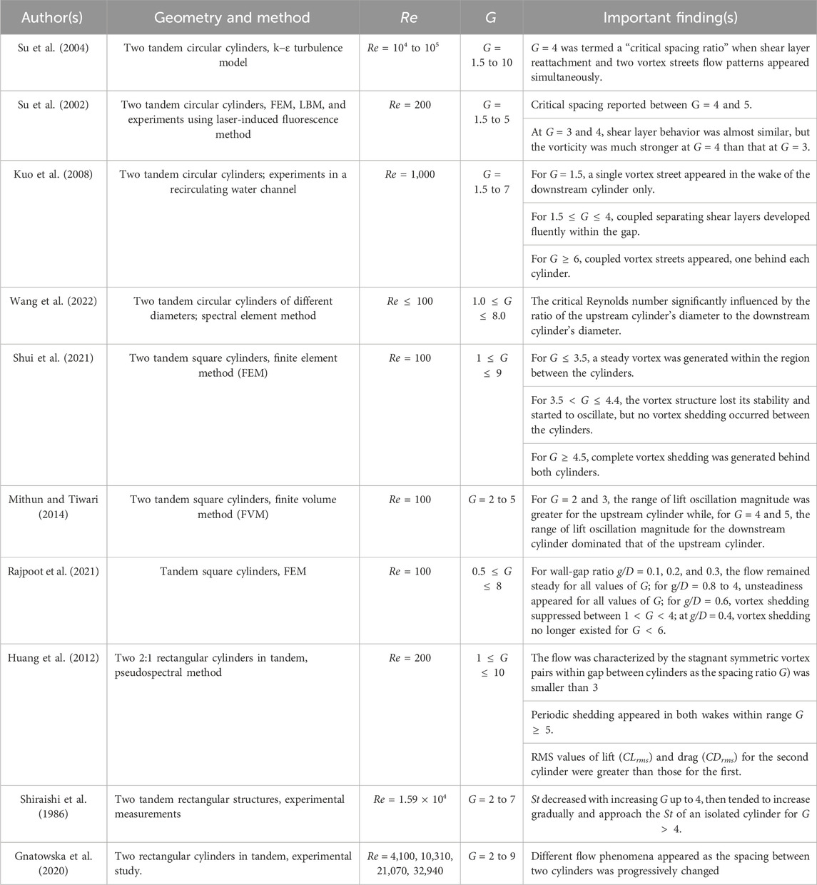
TABLE 1. Fluid flow characteristics around two bluff bodies reported in literature.
When multiple objects (more than two) appear in the fluid flow stream, the resulting forces and flow structure may significantly differ from those seen in case of two or a single body even at the same Reynolds number or gap spacings. Alam et al. (2017) observed the flow around three tandem circular cylinders by considering Re = 200, gap spacing between first and second cylinder (G1) = 3.5 to 5.25, and gap spacing between the second and third cylinder (G2) in the range 3.6–5.5. They categorized the flow structures as in-phase, antiphase, and intermediate, depending on G1 and G2. Eizadi et al. (2022) analyzed the transitions in the wake of six circular obstacles placed inline at Re = 40 to 180 and G = 0.5 to 18. They concluded that wake transitions of multiple cylinders depend not only on Re but also on G. Song et al. (2017) observed the flow patterns and force variations over four inline square cylinders by considering Re = 300 and G = 1.5 to 8. They reported that, when G
Studies describing the fluid flow around other geometries like airfoils have also been conducted (Bajalan et al., 2011; Mirzaei et al., 2012; Rangan and Santanu Ghosh, 2022; Abdolahipour, 2023). Another aspect of fluid–solid interactions is flow control around bluff bodies. Utilizing flow control strategies, efficient devices have been designed to save energy by minimizing flow-induced forces and controlling wake flow structures. Among various available flow controlling strategies, flow control through modulated pulse jet (Abdolahipour et al., 2021; Abdolahipour et al., 2022) and plasma actuator (Salmasi et al., 2013; Mohammadi and Taleghani, 2014; Taleghani et al., 2018) are frequently studied by researchers.
It can be concluded from this literature that the flow characteristics of multiple bodies are influenced by many parameters, including Re, G, B, AR, and
2 Numerical method
The current analysis utilizes the well-known numerical methodology, the lattice Boltzmann method (LBM). The simplified nature, easy implementation, and accuracy features of LBM make it more suitable than conventional methods for simulating fluid dynamics problems (Mohammad, 2011). This method involving two main steps, streaming and collision, has several advantages over the Navier–Stokes (NS) solvers. It has an explicit nature with conditional stability conditions (Chen and Doolen, 1998). The nonlinearity appearance in the case of NS equations does not appear in this method because the Boltzmann equation (BE) is quasi-linear. Pressure can be obtained through a simple procedure from the equation of state instead of dealing with the Laplace equation in each time step. LBM contains a variety of discrete models for simulating fluid flows. The current study is based upon the well-known two-dimensional nine-velocity directions (D2Q9, D indicates dimensions and Q the number of velocity directions) model (Figure 1) (Sukop and Throne, 2006).
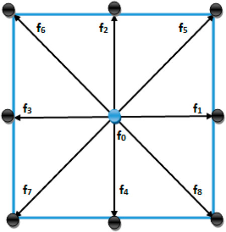
FIGURE 1. D2Q9 lattice model.
The discrete BE along a specified direction is
where
After discretization through finite differencing, the lattice Boltzmann equation (LBE) takes the following form:
where
For the current study, the following form of
where

TABLE 2. Weighting coefficients for the D2Q9 model.
Here, w0 are weight-associated with rest particle, wa are weights for particles moving along the axis, and wd are weights for particles moving diagonally.
Density and velocity are expressed in terms of
The fluid kinematic viscosity is expressed as
The values of
For some recent developments of LBM schemes regarding applications in different fields, readers are referred to Noori et al. (2019) and Noori et al. (2020).
3 Problem statement
The problem’s schematic diagram considered in this study is shown in Figure 2. This figure depicts a channel containing the two tandem rectangular cylinders placed in a fluid stream to be analyzed here. The height of the first cylinder (C1) is h1 and of the second cylinder (C2) is h2, and the width of both cylinders is denoted by D. In this study, h1 and h2 are discretized so as to have 40 and 30 lattices, respectively, while the width D has 20 lattices. Each cylinder is of a different aspect ratio (AR = height of cylinder/width of cylinder): the first cylinder has AR = 2:1 while the second has AR = 3:2. Xu = 10D is the distance from the channel entrance position to C1, and Xd = 20D is the distance from C2 to the domain outlet. The distance from the upper surface of C1 to the upper boundary is Yu = 8D, while Yb = 8D is the distance from the lower surface of C1 to the lower boundary of the domain. These lengths are selected based on the recommendations of previous research in order to have a minimal effect of domain size on results (Perumal et al., 2012). Channel length L varies as the gap between cylinders (G = s/D) varies, while the height H is fixed. All lengths in this study are non-dimensionalized using the characteristic length (D = 20).
FIGURE 2. Geometry of the problem.
The boundary conditions in this study are applied in terms of distribution functions. At the inlet position, uniform incoming flow (
4 Grid independence and code validation study
4.1 Grid independence
In order to ensure grid independence, we considered three different grid sizes (10, 20, and 40 points) around the outer surface of a single square cylinder at Re = 100 (Table 3). In terms of percentage variation, the values of physical variables like CDmean, St, and CLrms are more significantly impacted by the 10-point grid than the 40-point results. In comparison, the 20-point grid produced superior outcomes relative to 10 points. Furthermore, the convergence of a 40-point grid required significantly longer time, and there was no great variation in results at 20- and 40-point grid sizes. Therefore, we considered the 20-point grid for analysis for this study. This grid size follows recommendations based on lattice Boltzmann simulations for both single and multiple objects (Islam et al., 2018; Rahman et al., 2021). Note that the uniform meshing (
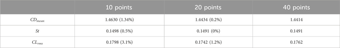
TABLE 3. Impact of spatial resolution on the physical properties of flow past a single square cylinder at Re = 100.
4.2 Code validation
For code validation, we performed computations for flow around a single square cylinder and quantitatively compared our results with the experimental and numerical results of other research considering Re = 100 (Table 4). Note that the results for the geometry considered in current work are not available in the literature. Therefore, the code validation study was performed for flow around a single square cylinder. This was based on the fact that the flow around a single cylinder serves as a benchmark problem for flow around bluff bodies. This practice was adopted in most previously published studies. Table 4 demonstrates good agreement among the current results and with those of other studies. Some minor deviations in results also appear. Note that the exact matching of results is not possible because several parameters, including the accuracy of the underlying numerical technique, mesh size, domain dimensions, and the dimensions of cylinders influence the outcomes. The overall agreement of current and previous results indicates that the current code calculated the results efficiently. Furthermore, we refer readers for the details of quantitative as well as qualitative validation in the case of flow around two and more inline arranged cylinders to Abbasi et al. (2018) and Abbasi et al. (2020).
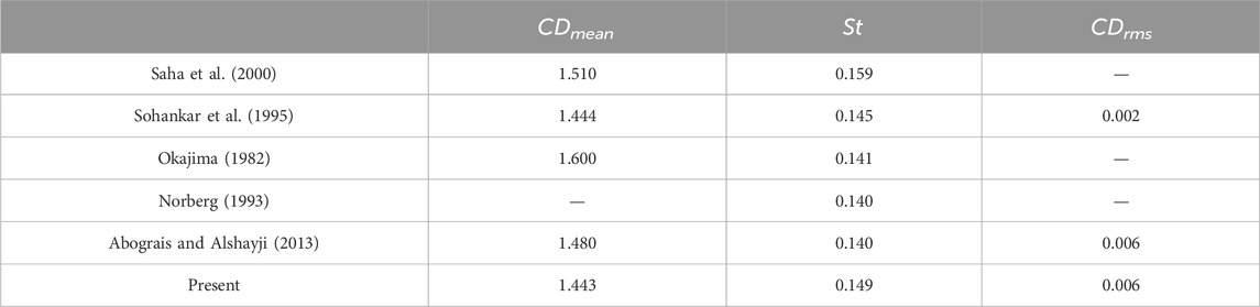
TABLE 4. Code validation in terms of single square cylinder at Re = 100.
It may therefore be concluded that our code is well established and that we can use it for flow around tandem arranged cylinders, done in the present study.
5 Results and discussion
The flow around two tandem rectangular cylinders with distinct aspect ratios was simulated at Re = 100 by considering different values of G progressively varying from 0.25 to 20. From previous studies, we can conclude that the flow structure mechanism around multiple rectangular cylinders appears to be a complicated phenomenon that depends on several parameters, including Re, G, and AR (Islam et al., 2018; Rahman et al., 2021). In the current study, the resulting flow regimes are specified into different patterns in terms of the creation of different shape vortices, wake structure mechanism, and the behavior of shear layers detaching from cylinder corners and interacting with each other. These different flow patterns depend on increasing values of G in this study. The prominent flow patterns observed in this study are the single slender body (SSB) flow found in the range G = 0.25–0.75, the shear layer reattachment (SLR) flow found in the range G = 1–4, the intermittent shedding (IS) flow mode found in the range G = 4.25–5.25, and the binary vortex street (BVS) flow found for G = 5.5–20, except at G = 8 where the single-row vortex street (SRVS) flow was observed. Similar flow patterns have been reported by Zdravkovich (1987) for flow around tandem bodies with different characteristics. In the following subsections, a comprehensive illustration for each flow pattern is presented and discussed.
5.1 Single slender body
The flow pattern noticed here at smaller gaps between two tandem rectangular cylinders is the SSB flow in the range 0.25
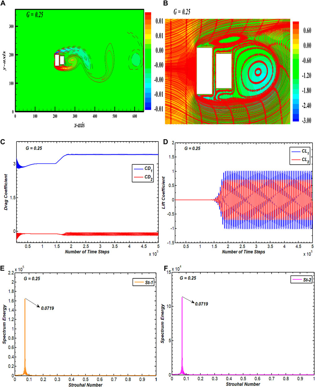
FIGURE 3. (A) Vorticity contour, (B) pressure streamlines, (C, D) drag and lift coefficients, and (E, F) spectral energy of CL for single slender body flow.
5.2 Shear layer reattachment
The second flow regime seen from current simulation results is SLR flow which extents in the range 1
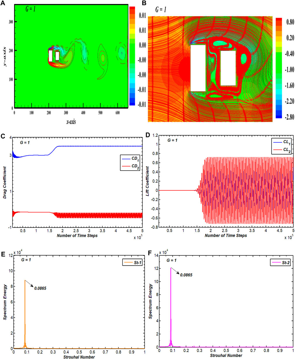
FIGURE 4. (A) Vorticity contour, (B) pressure streamlines, (C, D) drag and lift coefficients, and (E, F) power spectrum of CL for alternate reattachment flow.
5.3 Intermittent shedding
With increased distance between the cylinders, the flow structure mechanism and interactions of separated flow with C2 become entirely different from the SSB and SLR flow patterns (see Figure 5). In Figure 5A, the vorticity contour shows that the boundary layers separated out of the top and bottom sides of C1 join to form vortices in the gap before interacting with C2 because of the larger space between the cylinders. After that, these vortices impinge on C2 and form a vortex street in its wake (Figure 5A). There seems no definite pattern for movement of vortices, as was in case of SSB and SLR patterns. Furthermore, the structures of vortices in street differ from each other, and it can also be observed that the strength of vortices in this case is increased more than those seen in previous flow patterns. The pressure exhibits a fluctuating pattern, with alternating regions of maximum and minimum pressure (Figure 5B). These pressure variations correspond to irregularly shedding vortices. At the back of C1, the pressure reduces, implying the creation of a low-pressure zone, followed by a rapid increase in pressure as the flow merges to C2. The pressure becomes minimal in the near wake zone of C2. These alternately repeated pressure patterns generate a characteristic waviness in the pressure contour. From Figure 5B, the location, size, and behavior of the vortices shedding from both cylinders along with the wake pattern behind the cylinders is indicated by streamlines. These show that the fluid detachment occurs at the leading edges of C1 and that a recirculating eddy appears behind C1. The fluid then moves toward C2 where it splits again, forming another recirculating eddy in the near lower corner of C2. Both cylinders generate their own eddies because of the wider gap between them. The streamlines emerging from the bottom frontal edge of C1 move toward the upper frontal corner of C2, indicating irregularity of fluid movement within the gap. A similar trend prevails in the wake region, as indicated by streamlines. Due to such chaos and amalgamation in flow, this flow pattern is classified as IS flow, and it is seen in the range 4.25
FIGURE 5. (A) Vorticity contour, (B) pressure streamlines, (C, D) drag and lift coefficients, and (E, F) power spectrum of CL for intermittent shedding flow.
5.4 Binary vortex street
The BVS flow pattern ranges over the spacing values G = 5.5–20, except for G = 8, where a single-row vortex street (SRVS) pattern appeared (discussed in the next section) (Figure 6). In Figure 6A, the associated vorticity pattern for BVS is given, depicting that each cylinder generates its own vortex street and that the vortex street behind C2 is binary because the movement of the vortices is in a parallel dual line of clockwise and anticlockwise vortices. The vortices after C2 are elliptically shaped with almost similar sizes. Zdravkovich (1987) also reported similar characteristics of BVS for flow-past coupled tandem circular cylinders for the spacing range G > 3.4 to 3.8. Figure 6B shows that the pressure varies randomly inside the domain in this flow pattern. Instead of a minimal pressure zone in the back of C2, as was seen in previous flow patterns, the pressure now seems minimal at the corners of C1. This distribution of pressure corresponds to the single cylinder case. This can be attributed to the increased gap spacing in which wake interference effects are minimized. This phenomenon becomes more prominent in BVS flow as G further increases. The streamlines in contour show larger recirculation zones within the gaps and after C2. In this case, the eddies appearing within the gap region and after C2 differ in shape and size due to changed vortex structures from the other flow patterns in this study. The CD for C1 has periodic variations, while the CD for C2 has initial fluctuating behavior which eventually settles to being periodic (Figure 6C). The lift coefficients become periodic for both cylinders after a short interval of linear behavior (Figure 6D). The CL oscillations have sufficiently higher amplitudes than SSB, SLR, and IS flow patterns due to the elliptically shaped vortices appearing after the cylinders. The periodic oscillation of the lift force demonstrates the domination of wake frequency within the spectrum energy graph (Figures 6E,F). There thus appears only a single peak in each case of the power spectrum plot.
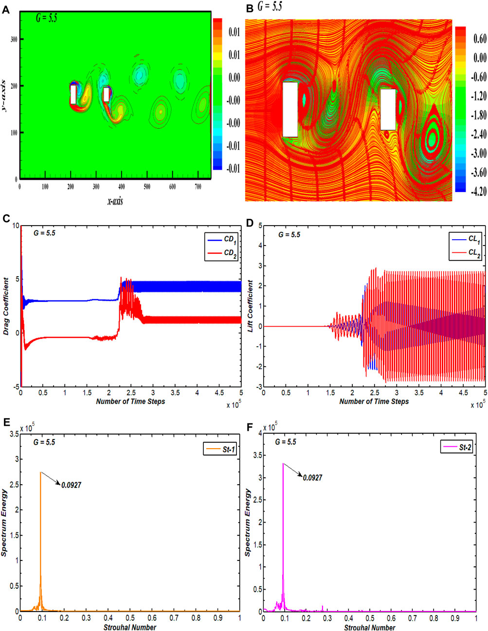
FIGURE 6. (A) Vorticity profile, (B) pressure streamlines, (C, D) drag and lift coefficients, and (E, F) power spectrum of CL for binary vortex street flow.
5.5 Single-row vortex street
The SRVS flow pattern in the wake of both cylinders is observed at only one gap spacing value—G = 8 in this study (Figure 7). The corresponding vorticity contour for the SRVS flow pattern is presented in Figure 7A, which shows that the vortices travel in a single row throughout the computational domain. The vortices in the wake of each cylinder are elongated and merge in the wake of C2. The pressure seems to be higher at the front surface of C1 and minimal at the corners and at back surface of C2 (Figure 7B). Here, the stagnation point is generated, showing that the flow is slowed due to the presence of the cylinder. The flow separates from the corners of the cylinders, indicating a low-pressure area. The lowest pressure value appears at back surface of C2. This low-pressure area causes the periodic shedding of vortices in the wake of each cylinder. In Figure 7B, the streamlines depict a distinct pattern of alternating vortex shedding from each cylinder. The streamlines appear to be curvy and firmly packed together in the center of the wake, indicating the existence of strong vorticity. Due to this, the drag as well as lift coefficients appear to be significantly impacted for both cylinders (Figures 7C,D). Since each cylinder sheds its own SRVS, the lift on the second cylinder is more stabilized than the IS and BVS flow pattern. The amplitude of consecutive cycles of the lift coefficients for both cylinders lessen compared to the IS and BVS flow patterns. This can be attributed to the individual shedding of vortices from both cylinders in a single row. A comparison with the SSB and SLR flow patterns reveals a significant rise in the amplitude of consecutive CL cycles for both cylinders due to the elongated recirculating regions of vorticity in the wake of both cylinders. These graphs also show that the amplitude of both force coefficients is higher in the case of second cylinder than of first. This is due to wake interference effect of C1 on the second cylinder. Due to SRVS flow pattern and the smooth passage of vortices in the domain, the power spectrum of the lift coefficient graph for both cylinders indicates a similar peak value (Figures 7E,F).
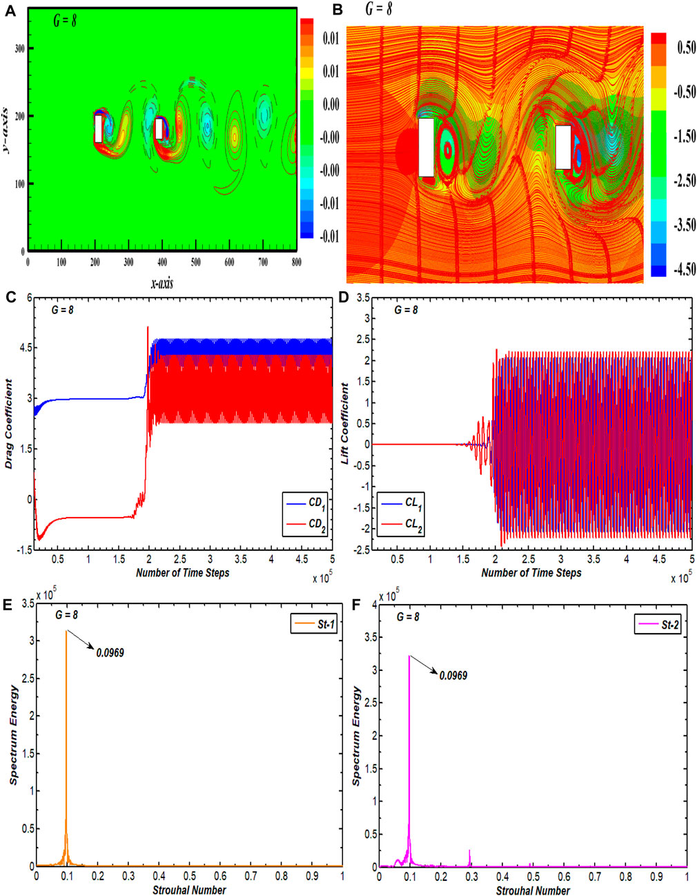
FIGURE 7. (A) Vorticity profile, (B) pressure streamlines, (C, D) drag and lift coefficients, and (E, F) power spectrum of CL for single vortex street flow.
6 Force statistics
Variations of various fluid force parameters acting on both cylinders with varying gap spacing is presented in this section in order to analyze the influence of G on the forces. The parameters considered for this purpose are CDmean, St, CDrms, CLrms, amplitude of the drag coefficient (CDamp), and amplitude of the lift coefficient (CLamp). Figure 8 presents the effect of G on variations of these parameters at Re = 100.
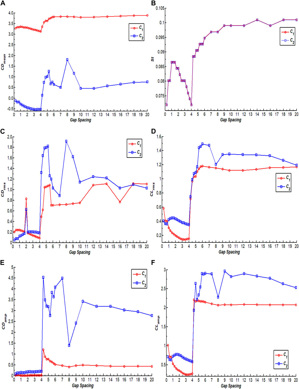
FIGURE 8. Gap spacing effect on the variation of (A) CDmean, (B) St, (C) CDrms, (D) CLrms, (E) CDamp, and (F) CLamp.
The variation of CDmean for flow around two tandem rectangular cylinders with increasing G is presented in Figure 8A. It can be observed that CDmean of C1 is greater than CDmean of C2 for all chosen values of G because the incoming flow initially interacts with C1 and thus exerts maximum drag force on C1. Another possible reason that C1 experiences significantly higher drag force than C2 is that it has higher AR. Relating the variations of drag force coefficient, it is apparent that the change in flow patterns significantly affects the drag force. In the range G = 0.25 to 1, the average drag on C1 slightly increases and then shows decreasing behavior until G = 4. It then increases with increasing G and approaches its maximum value at G = 20. Note that, at G = 1, the flow pattern changes from SSB to SLR, while after G = 4, the flow pattern changes from SLR to IS. The CDmean of C2 is negative and initially decreases until G = 4. Huang et al. (2012) also observed the negative value of CDmean for C2 for flowing past 2:1 rectangular cylinders in tandem at Re = 200. After G = 4, it jumps from negative to positive values due to a change in flow pattern from SLR to IS. The negative values of CDmean indicate that the drag force acts as a thrust force, thus generating a backflow due to narrow gaps between cylinders. The minimum value of CDmean for both cylinders can be seen at G = 4, while the maximum for C2 occurs at G = 8, and CDmean of C1 is maximum at G = 20. Figure 8A also shows that, after G = 10, the influence of gap spacing on CDmean of both cylinders decreases. Figure 8B presents the variation of St of both cylinders with G. Both cylinders have same St for all G, indicating that the vortices shed from both cylinders with same frequency notwithstanding whether both cylinders have different ARs. Rahman et al. (2021) also found similar behavior in St for flow past three rectangular cylinders. Initially for G = 0.25 to 0.75, St shows increasing behavior. SSB flow was observed in this range of gap spacing. In the range G = 1.75 to 4, it shows decreasing behavior, which indicates that the shedding frequency decreases due to the push of shear layers inside the gaps between cylinders. After that it increases with increasing G and approaches the local maximum value for both cylinders at G = 14. The minimum value of St can be observed at G = 4 for both cylinders where the SLR flow pattern was seen. The variation of CDrms of both cylinders at different values of G is presented in Figure 8C. Initially, when G = 0.25 to 1, the CDrms of C1 slightly increased and then showed decreasing behavior in the range G = 1.25 to 1.75 where the SLR flow is observed. The CDrms of C2 show increasing behavior in the range G = 0.25 to 1.75. The CDrms of both cylinders jump to higher values at G = 2 and then again show decreasing behavior until G = 4. After G = 4, it jumps to higher values due to a change in flow pattern from SLR to IS. The CDrms of both cylinders show a mix of increasing and decreasing behaviors as G increases further. The minimum value of CDrms for both cylinders can be noticed at G = 4, while the maximum value of CDrms of C1 appears at G = 18, and CDrms of C2 is maximum at G = 8 where the SRVS flow pattern was reported. The effect of varying G on CLrms of both cylinders is shown in Figure 8D. This graph depicts that, in the range G = 0.25 to 4, the CLrms of C1 shows decreasing behavior. After that, it increases with increasing G and thus approaches its local maximum value at G = 6. The CLrms of C2 shows decreasing behavior initially in the SSB flow pattern regime and, after that, slightly increases and then shows decreasing behavior until G = 4. The CLrms curves then show an increasing trend to higher values for both cylinders. Note that the IS flow pattern is observed in this range. At G = 4.5 to 7.75, the value of CLrms of C2 increases and then suddenly decreases, which can be observed at G = 8 because of flow pattern change from BVS to SRVS flow. The variation of CDamp for both cylinders with varying G is shown in Figure 8E. It can be observed that, until G = 4, CDamp for both cylinders is almost constant, indicating little change in amplitude of drag force in this spacing range. After G = 4, CDamp jumps to the highest values for both cylinders due to the appearance of the IS flow pattern. Note that, in this flow pattern, the vortices appear to be in an irregular pattern in the wake of both cylinders. This graph also shows that the higher spacing values result in higher amplitude drag force than the smaller spacing values. The variation of CLamp of both cylinders shown in Figure 8F indicates that the C2 bears higher amplitude than C1 at almost all spacing values. This is due to the wake interference effects of C1 on C2. Shui et al. (2021) also reported similar results in CLamp for flow around two tandem square cylinders. Initially, CLamp corresponding to C1 decreased until G = 4 but, after G = 4, it suddenly increased to a higher value and became almost independent of G, showing negligible modifications. In the range G = 0.25 to 0.75, the CLamp of C2 shows decreasing behavior. After G = 4, the CLamp of both cylinders has sudden jumps (Figure 8F). The minimum value of CLamp of both cylinders can be observed at G = 4 where the SLR flow pattern is observed. Its maximum value for C1 appears at G = 4.25 and the maximum value for C2 at G = 9.
7 Conclusion
Numerical calculations were performed to analyze the fluid flow around two vertically positioned rectangular cylinders in tandem arrangement using the lattice Boltzmann method. The cylinders considered in this study were of different aspect ratios. The main goal of this study was to determine the wake structures under the effect of gap spacing in the range G = 0.25 to 20 at Re = 100. The results were presented and discussed in the form of vorticity contour visualizations, pressure streamline contours, variation of drag, and lift coefficient against time. Fluid force parameters of average drag coefficient, Strouhal number, rms values of drag, lift coefficients, and the amplitudes of these force coefficients were also analyzed under the impact of changing gaps between cylinders. The important findings of this study are:
(1) Bearing various characteristics, five different wake flow patterns were observed in this study depending on various ranges of gap spacings: i) single slender body, ii) shear layer reattachment, iii) intermittent shedding, iv) binary vortex street, and v) single-row vortex street.
(2) The single slender body flow pattern, observed in the range G = 0.25 to 0.75, consists of single vortex street in the down wake area of C2, without any gap flow, similar to the flow around a single bluff body. The fluid forces in this flow pattern varied periodically with similar amplitude as time proceeded.
(3) In the range G = 1 to 4, the shear layer reattachment flow was observed. In this flow pattern, the strength of vortices increased in the down wake region. The amplitude of lift force coefficient on both cylinders also increased more than single slender body flow. The secondary cylinder interaction frequency impact was also observed in this flow pattern.
(4) In the range G = 4.25 to 5.25, the intermittent shedding flow pattern was observed. In this flow pattern, the vortices did not exhibit any proper pattern, but instead chaos was observed in the flow structure. The CD varied irregularly with random dips and peaks due to the flow structure transitions between larger and smaller sized vortices.
(5) The binary vortex street flow pattern was found in the range G = 5.5 to 20 except at G = 8, where the single-row vortex street flow pattern was observed. In the binary vortex flow pattern, both cylinders generated their own vortex street, while the vortex street in the down wake region traveled in a double row of parallel vortices. The vortex formation region enlarged in this range of gap spacing, corresponding to both flow patterns, which resulted in higher magnitude drag and lift forces on cylinders.
(6) It was observed that C2 experienced negative drag in the spacing range between G = 0.25 to 4, while C1 had positive values of CDmean for all G. The negative drag force on C2 jumped to positive as the flow pattern changed from shear layer reattachment to intermittent shedding flow. Furthermore, the CLrms, CDrms, CLamp, and CDamp for C2 were mostly higher than corresponding values on C1 for all values of G.
(7) Although C2 was shielded by C1 and faces low pressure at smaller spacing values, it was also subjected to pressure change due to the changes in flow patterns as gap spacing progressively increased. Furthermore, the magnitude of pressure on both cylinders changed due to change in flow patterns.
(8) At G = 4 and 8, the fluid force parameters like CDmean, St, CDrms, CLrms, CDamp, and CLamp achieved either maximum or minimum values or had sudden jumps in values. The flow structure at these spacing values also exhibits complexity. Both spacing values are hence critical for fluid flow dynamics around the geometry considered in this study.
Data availability statement
The raw data supporting the conclusions of this article will be made available by the authors without undue reservation.
Author contributions
WA: conceptualization, project administration, supervision, and writing–review and editing. ME: formal analysis, methodology, validation, and writing–original draft. HR: visualization and writing–review and editing. ZU: funding acquisition, resources, and writing–review and editing. MH: funding acquisition, supervision, and writing–review and editing. KS: funding acquisition and writing–review and editing.
Funding
The author(s) declare that financial support was received for the research, authorship, and/or publication of this article. This work was supported by King Saud University, Riyadh, Saudi Arabia, under Researchers Supporting Project Number RSP2024R18.
Conflict of interest
The authors declare that the research was conducted in the absence of any commercial or financial relationships that could be construed as a potential conflict of interest.
Publisher’s note
All claims expressed in this article are solely those of the authors and do not necessarily represent those of their affiliated organizations or those of the publisher, the editors and, the reviewers. Any product that may be evaluated in this article, or claim that may be made by its manufacturer, is not guaranteed or endorsed by the publisher.
References
Abbasi, W. S., Islam, S. U., Faiz, L., and Rahman, H. (2018). Numerical investigation of transitions in flow states and variation in aerodynamic forces for flow around square cylinders arranged inline. Chin. J. Aeronautics 31 (11), 2111–2123. doi:10.1016/j.cja.2018.08.020
Abbasi, W. S., Mahmood, R., and Naheed, A. (2020). On the wake interference effects for flow around tandem bodies. J. Braz. Soc. Mech. Sci. Eng. 42, 53. doi:10.1007/s40430-019-2137-5
Abdolahipour, S. (2023). Effects of low and high frequency actuation on aerodynamic performance of a supercritical airfoil. Front. Mech. Eng. 9, 1290074. doi:10.3389/fmech.2023.1290074
Abdolahipour, S., Mani, M., and Taleghani, A. S. (2021). Parametric study of a frequency-modulated pulse jet by measurements of flow characteristics. Phys. Scr. 96, 125012. doi:10.1088/1402-4896/ac2bdf
Abdolahipour, S., Mani, M., and Taleghani, A. S. (2022). Experimental investigation of flow control on a high-lift wing using modulated pulse jet vortex generator. J. Aerosp. Eng. 35 (5). doi:10.1061/(ASCE)AS.1943-5525.0001463
Abograis, A., and Alshayji, A. (2013). Reduction of fluid forces on a square cylinder using passive control methods. Boston, USA: COMSOL Conference.
Aboueian, J., and Sohankar, A. (2017). Identification of flow regimes around two staggered square cylinders by a numerical study. Theory Comput. Fluid Dyn. 31, 295–315. doi:10.1007/s00162-017-0424-2
Adeeb, E., Haider, B. A., and Sohn, C. H. (2018). Flow interference of two side-by-side square cylinders using IB-LBM- Effect of corner radius. Results Phys. 10, 256–263. doi:10.1016/j.rinp.2018.05.039
Ahmad, S., Islam, S. U., Nazeer, G., and Zhou, C. Y. (2021). Numerical investigation of Strouhal number discontinuity and flow characteristics around single rectangular cylinder at low aspect ratios and Reynolds numbers. J. Braz. Soc. Mech. Sci. Eng. 43 (315), 1–26. doi:10.1007/s40430-021-03040-2
Alam, Md. M., Bai, H., and Zhou, Y. (2016). The wake of two staggered square cylinders. J. Fluid Mech. 801, 475–507. doi:10.1017/jfm.2016.303
Alam, Md. M., Derakhshandeh, J. F., Zheng, Q., Rehman, S., Ji, C., and Zafar, F. (2017). “The flow around three tandem circular cylinders,” in The world congress on Advances in Structural Engineering and Mechanics (ASEM 17), Ilsan(Seoul), Korea, August 28 - September 1, 2017.
Bajalan, S., Shadaram, A., Hedayat, N., and Taleghani, A. S. (2011). Experimental study of frequency behavior for a circular cylinder behind an airfoil. World Acad. Sci. Eng. Technol. Int. J. Aerosp. Mech. Eng. 5, 2349–2353.
Belloli, M., Giappino, S., Morganti, S., Muggiasca, S., and Zasso, A. (2014). Vortex induced vibrations at high Reynolds numbers on circular cylinders. Ocean. Eng. 94, 140–154. doi:10.1016/j.oceaneng.2014.11.017
Burattini, P., and Agrawal, A. (2013). Wake interaction between two side-by-side square cylinders in channel flow. Comput. Fluids 77, 134–142. doi:10.1016/j.compfluid.2013.02.014
Chakraborty, S., Chaterjee, S., and Kumar, R. (2022). Effect of gap ratio on flow influenced actions of two circular cylinders in side-by-side arrangement. J. Mines, Metals Fuels 70 (3A), 15–20. doi:10.18311/jmmf/2022/30662
Chen, S., and Doolen, G. D. (1998). Lattice Boltzmann method for fluid flows. Annu. Rev. Fluid Mech. 30, 329–364. doi:10.1146/annurev.fluid.30.1.329
Eizadi, H., An, H., Zhu, H., Chang, L., and Cheng, L. (2022). Wake transitions of six tandem circular cylinders at low Reynolds numbers. Phys. Fluids 34 (2), 1–49. doi:10.1063/5.0080268
Gnatowska, R., Sobczyk, J., and Wodziak, W. (2020). Stability of flow around two rectangular cylinders in tandem. Appl. Phys. Mech. Material Eng. 138 (2), 295–298. doi:10.12693/APhysPolA.138.295
Huang, Z., Xi, G., and Zhang, W. (2012). Numerical simulation of spacing effects on the flow past two 2:1 rectangular cylinders in tandem at Re = 200. Proc. Am. Soc. Mech. Eng. 2012, 1–9. doi:10.1115/FEDSM2012-72157
Islam, S. U., Manzoor, R., Ying, Z. C., and Islam, Z. U. (2018). Numerical investigation of different aspect ratios for flow past three inline rectangular cylinders. J. Braz. Soc. Mech. Sci. Eng. 40, 410. doi:10.1007/s40430-018-1334-y
Islam, S. U., Zhou, C. Y., Shah, A., and Xie, P. (2012). Numerical simulation of flow past rectangular cylinders with different aspect ratios using the incompressible lattice Boltzmann method. J. Mech. Sci. Technol. 26 (4), 1027–1041. doi:10.1007/s12206-012-0328-4
Kuo, C. H., Chein, S. M., and Hsieh, H. J. (2008). Self-sustained oscillations between two tandem cylinders at Reynolds number 1000. Exp. Fluids 44, 503–517. doi:10.1007/s00348-007-0409-9
Kuzmina, K., and Marchevsky, I. (2021). Flow simulation around circular cylinder at low Reynolds numbers. J. Phys. Conf. Ser. 1715, 1–7. doi:10.1088/1742-6596/1715/1/012067
Lee, S. J., Mun, G. S., Park, Y. G., and Ha, M. Y. (2019). A numerical study on fluid flow around two side-by-side rectangular cylinders with different arrangements. J. Mech. Sci. Technol. 33 (7), 3289–3300. doi:10.1007/s12206-019-0624-3
Ma, S., Kang, C.-W., Lim, T.-B. A., Wu, C.-H., and Tutty, O. (2017). Wake of two side-by-side square cylinders at low Reynolds numbers. Phys. Fluids 29, 1–23. doi:10.1063/1.4979134
Marson, F., Thorimbert, Y., Chopard, B., Ginzburg, I., and Latt, J. (2021). Enhanced single-node lattice Boltzmann boundary condition for fluid flows. Phys. Rev. E 103 (5), 053308. doi:10.1103/physreve.103.053308
Mirzaei, M., Taleghani, A. S., and Shadaram, A. (2012). Experimental study of vortex shedding control using plasma actuator. Appl. Mech. Mater. 186, 75–86. doi:10.4028/www.scientific.net/amm.186.75
Mithun, M. G., and Tiwari, S. (2014). Flow past two tandem square cylinders vibrating transversely in phase. Jpn. Soc. Fluid Mech. 46, 055509–055532. doi:10.1088/0169-5983/46/5/055509
Mittal, S., and Raghuvanshi, A. (2001). Control of vortex shedding behind circular cylinder for flows at low Reynolds numbers. Int. J. Numer. Methods Fluid 35, 421–447. doi:10.1002/1097-0363(20010228)35:4<421::aid-fld100>3.0.co;2-m
Mohammad, A. A. (2011). Lattice Boltzmann method: fundamentals and engineering applications with computer codes. Berlin: Springer.
Mohammadi, M., and Taleghani, A. S. (2014). Active flow control by dielectric barrier discharge to increase stall angle of a naca0012 airfoil. Arabian J. Sci. Eng. 39, 2363–2370. doi:10.1007/s13369-013-0772-1
Noori, M. S., Rahni, M. T., and Taleghani, A. S. (2020). Effects of contact angle hysteresis on drop manipulation using surface acoustic waves. Theor. Comput. Fluid Dyn. 34, 145–162. doi:10.1007/s00162-020-00516-0
Noori, S. M. S., Rahni, M. T., and Taleghani, S. A. S. (2019). Multiple-relaxation time color-gradient lattice Boltzmann model for simulating contact angle in two-phase flows with high density ratio. Eur. Phys. J. Plus 134, 399. doi:10.1140/epjp/i2019-12759-x
Norberg, C. (1993). Flow around rectangular cylinders: pressure forces and wake frequencies. J. Wind Eng. Industrial Aerodynamics 49, 187–196. doi:10.1016/0167-6105(93)90014-f
Octavianty, R., Asai, M., and Inasawa, A. (2016). Experimental study on vortex shedding and sound radiation from a rectangular cylinder at low Mach numbers. Jpn. Soc. Aeronautical Space Sci. 59 (5), 261–268. doi:10.2322/tjsass.59.261
Okajima, A. (1982). Strouhal numbers of rectangular cylinders. J. Fluid Mech. 123, 379–398. doi:10.1017/s0022112082003115
Perumal, D. A., Kumar, V. S., and Dass, K. A. (2012). Numerical simulation of viscous flow over a square cylinder using lattice Boltzmann method. ISRN Math. Phys. 2012, 1–16. doi:10.5402/2012/630801
Rahman, H., Islam, S. U., Abbasi, W. S., Manzoor, R., Amin, F., and Alam, Z. (2021). Numerical computations for flow patterns and force statistics of three rectangular cylinders. Math. Problems Eng. 2021, 1–12. doi:10.1155/2021/9991132
Rajpoot, R. S., Anirudh, K., and Dhinakaran, S. (2021). Numerical investigation of unsteady flow across tandem cylinders near a moving wall at Re = 100. Case Stud. Therm. Eng. 26, 1–14. doi:10.1016/j.csite.2021.101042
Rangan, M. L. N. V. K., and Santanu Ghosh, S. (2022). A face-based immersed boundary method for compressible flows using a uniform interpolation stencil. Front. Mech. Eng. 8, 903492. doi:10.3389/fmech.2022.903492
Saha, A. K., Muralidhar, k., and Biswas, G. (2000). Transition and chaos in two-dimensional flow past a square cylinder. J. Eng. Mech. 126, 523–532. doi:10.1061/(asce)0733-9399(2000)126:5(523)
Salmasi, A., Shadaram, A., and Taleghani, A. S. (2013). Effect of plasma actuator placement on the airfoil efficiency at poststall angles of attack. IEEE Trans. Plasma Sci. 41 (10), 3079–3085. doi:10.1109/tps.2013.2280612
Sarvghad, , Hesam, M., and Navid, N. (2011). Numerical simulation of flow over two side-by-side circular cylinders. J. Hydrodynamics 23 (6), 792–805. doi:10.1016/S1001-6058(10)60178-3
Shiraishi, N., Matsumoto, M., and Shirato, H. (1986). On aerodynamic instabilities of tandem structures. J. Wind Eng. Industrial Aerodynamics 23, 437–447. doi:10.1016/0167-6105(86)90061-9
Shui, Q., Duan, C., Wang, D., and Gu, Z. (2021). New insights into numerical simulations of flow around two tandem square cylinders. AIP Adv. 11, 1–14. doi:10.1063/5.0042797
Sohankar, A., Davidson, L., and Norberg, C. (1995). “Numerical simulation of unsteady flow around a square two-dimensional cylinder.” in. Twelfth Australasian Fluid Mechanics Conference the University of Sydney, Australia, 4-8 December 2022, 517–520.
Song, Y., Zhu, R., Simon, T. W., and Xie, G. (2017). Computational fluid dynamics modeling patterns and force characteristics of flow over in-line four square cylinders. Therm. Sci. 21 (00), 2553–2563. doi:10.2298/tsci170211035s
Su, Z., Liu, Y., and So, R. M. C. (2004). Numerical simulation of two tandem circular cylinders in a turbulent flow. Flow-Induced Vib. 2004, 297–302.
Su, Z. D., Guo, Z. L., So, R. M. C., and Liu, Y. (2002). “Two- and three-dimensional study of two tandem circular cylinders in a cross flow,” in Conference on Bluff Body Wakes and Vortex-Induced Vibrations, Port Douglas, Australia, 17-20 December 2002, 1–5.
Sukop, M. C., and Throne, D. T. (2006). Lattice Boltzmann modeling: an introduction for geo-scientists and engineers. Berlin: Springer.
Taleghani, A. S., Abdollah Shadaram, A., Mirzaei, M., and Abdolahipour, S. (2018). Parametric study of a plasma actuator at unsteady actuation by measurements of the induced flow velocity for flow control. J. Braz. Soc. Mech. Sci. Eng. 40, 173. doi:10.1007/s40430-018-1120-x
Tao, S., He, Q., Chen, B., Yang, X., and Huang, S. (2018). One-point second-order curved boundary condition for lattice Boltzmann simulation of suspended particles. Comput. Math. Appl. 76 (7), 1593–1607. doi:10.1016/j.camwa.2018.07.013
Wang, J., Shan, X., and Liu, J. (2022). First instability of the flow past two tandem cylinders with different diameters. Phys. Fluids 34, 1–19. doi:10.1063/5.0098204
Wolf-Gladrow, D. A. (2000). Lattice-gas cellular automata and lattice Boltzmann models: an introduction. Berlin: Springer.
Ye, Z.-H., Sun, X., and Zhang, J.-Z. (2019). Flow-induced vibrations of two staggered circular cylinders at low Reynolds number. J. Vib. Test. Syst. Dyn. 3 (1), 39–53. doi:10.5890/jvtsd.2019.03.004
Zdravkovich, M. M. (1987). The effects of interference between circular cylinders in cross flow. J. Fluids Struct. 1, 239–261. doi:10.1016/s0889-9746(87)90355-0
Zhang, Z., and Zhang, X. (2012). Direct simulation of low-Re flow around a square cylinder by numerical manifold method for Navier-Stokes equations. J. Appl. Math. 2012, 1–14. doi:10.1155/2012/465972
Nomenclature
Keywords: rectangular cylinders, aspect ratio, flow structure, drag, gap spacing, lift
Citation: Abbasi WS, Ehsan M, Rahman H, Uddin Z, Hassan MM and Saleem K (2024) Analysis of the wake mechanism in external flow around tandem bluff bodies with different aspect ratios. Front. Mech. Eng 10:1341618. doi: 10.3389/fmech.2024.1341618
Received: 20 November 2023; Accepted: 03 January 2024;
Published: 05 February 2024.
Edited by:
Arash Shams Taleghani, Aerospace Research Institute, Tehran, IranReviewed by:
Shi Tao, Dongguan University of Technology, ChinaSoheila Abdolahipour, Aerospace Research Institute, Iran
Mahdi Sheikholeslam, K.N.Toosi University of Technology, Iran
Copyright © 2024 Abbasi, Ehsan, Rahman, Uddin, Hassan and Saleem. This is an open-access article distributed under the terms of the Creative Commons Attribution License (CC BY). The use, distribution or reproduction in other forums is permitted, provided the original author(s) and the copyright owner(s) are credited and that the original publication in this journal is cited, in accordance with accepted academic practice. No use, distribution or reproduction is permitted which does not comply with these terms.
*Correspondence: Waqas Sarwar Abbasi, d2FxYXMtNTU1QGhvdG1haWwuY29t