 I. Elvira
 J. Soler
 J. Herguido
 M. Menéndez
- Catalysis and Reactor Engineering Group (CREG), Aragon Institute for Engineering Research (I3A), Department of Chemical and Environmental Engineering, Universidad de Zaragoza, Zaragoza, Spain
A new kind of ceramic-polymeric membranes has been prepared and characterized towards its use in membrane reactors for synthesis of methanol from CO2 and hydrogen. In this way, PBI membranes were prepared on a ceramic support by varying parameters of the preparation process. The effect of those parameters on the separation of the compounds involved in the reaction was measured under conditions (temperature, pressure and gas composition) simulating those of the reaction. The prepared membranes were able to selectively remove water from a mixture containing hydrogen and CO2. H2O/CO2 and H2O/H2 separation factors over 18 and 12, respectively, were achieved at 160°C. The separation factors decreased by increasing the temperature with a 3-layer membrane but were quite stable with a 4-layer membrane.
1 Introduction
Our society is in the way from the fossil fuels dependence to a sustainable use of renewable energy, and the use of liquid fuels derived from renewable hydrogen and CO2 is one of the most powerful tools to achieve this change (Kamkeng et al., 2021). One of the most interesting substitutes for fossil fuels is e-methanol. The paradigm of the methanol economy was proposed two decades ago as an alternative to the current model of fossil fuel consumption by the Nobel Prize in Chemistry George A. Olah (Olah, 2005). Methanol synthesis is an equilibrium reaction in which hydrogen and carbon dioxide react to form methanol and water. One of the biggest problems posed by this synthesis is that the equilibrium of the reaction is only slightly shifted towards the formation of products, so high yields of methanol are not achieved even using a very high pressure.
For this reason, the use of membrane reactors has been proposed, in which the membrane separates the products (usually water is the removed product) from the reaction mixture as they are formed, to shift the equilibrium towards the formation of products, according to the Le Chatelier’s principle. Leonzio, (2018) reviewed the literature on the production of methanol from CO2/H2 mixtures.
To date, mainly three types of materials have been disclosed as membranes for membrane reactors for methanol production: silica-alumina composites (Sea and Lee, 2003; Farsi and Jahanmiri, 2011), zeolites (Menéndez et al., 1999; Barbieri et al., 2002; Gallucci et al., 2004; Gorbe et al., 2018) and polymers (Struis et al., 1996).
The use of Nafion in a membrane reactor was proposed but the maximum operating temperature of this polymer is around 200°C, which is lower than the usual reaction temperature (Struis and Stucki, 2001). To try to avoid this drawback, polymer–ceramic membranes have been used in fields like pervaporation (Liu et al., 2012) and high temperature proton exchange membrane fuel cells (Eguizábal et al., 2011). Silicone rubber membranes deposited on ceramic supports can selectively remove water from a mixture of gases containing hydrogen and CO2 at temperatures up to 220°C (Juarez et al., 2021).
Polybenzimidazole (PBI) has been explored for fabricating hollow fiber membranes (HFMs) employed in liquid and gas separations since the 1970s because it exhibits exceptional thermal and chemical stability (Cong et al., 2021). More attention has been given to identify and functionalize new types of fillers such as covalent organic frameworks with excellent H2/CO2 separation characteristics to enhance their compatibility with PBI and therefore its separation performance (Bitter and Tashvigh, 2022). At the moment, PBI-based HFMs exhibit great potential in the fields of wastewater reuse, organic solvent recovery, and efficient H2 and CO2 separation for hydrogen production and CO2 capture (Wang et al., 2022).
The objective of this work is to know the behavior of several polymeric-ceramic composite membranes to be employed in membrane reactors for the methanol synthesis reaction. To do this, a series of PBI membranes will be prepared, varying certain parameters of the preparation process to determine the effect that these parameters have when separating H2, CO2 and H2O. Subsequently, the different membranes will be analyzed, carrying out tests under diverse temperature and pressure conditions, to know the working conditions that most favor the separation of water from gases. A series of tests will be carried out in which a mixture of hydrogen, carbon dioxide and water vapor will be fed at conditions simulating those of methanol production, in order to know their separation capacity (i.e., H2O permeance and H2O/H2 and H2O/CO2 separation factors) if they were used in a membrane reactor.
2 Materials and methods
2.1 Membrane preparation
Three different techniques have been utilized for the preparation of polymeric membranes on the internal side of ceramic supports. The supports were alumina microfiltration membranes (Inocermic GmbH) with a thin separation layer in the internal side with 200 nm pores. The ceramic supports were 10 mm o. d. and 7 mm i. d., with a permeable length of 5 cm. In all cases, a solution of PBI dissolved in di-methyl-acetamide (DMAc) was used as a precursor for the polymeric membrane, in different concentrations, to verify the effect that the concentration of the polymer in the starting solution has on the properties of the membrane when separating gases. The techniques used were: dip-coating, suction and emptying and external vacuum deposition.
- The dip-coating technique consisted of placing the ceramic support vertically and introducing the PBI solution in DMAc through the upper part of the cylindrical support until the entire support is filled and extracting the solution from below with the suction of a peristaltic pump, so that a thin layer of solution is deposited on the support. When the solvent evaporates, a layer of polymer remains. Several membranes have been synthesized by this method using different extraction speeds of the solution to know the effect that speed has on the functioning of the membrane.
- The suction and emptying technique consisted of placing the ceramic support vertically and placing a pipette sucker on top of the support. The lower part of the support is introduced into a flask containing the PBI solution and the solution is sucked until the support is filled to the top with it. Subsequently, the pipette sucker is released from the support and the PBI solution is allowed to freely fall through the bottom of the support, leaving a thin layer of solution deposited. This technique is equivalent to a dip-coating with a high speed of descent of the solution.
- The technique with external vacuum consisted of filling the ceramic support completely with PBI solution, and then introducing the solution-filled support in a container, which is evacuated, with the intention that the vacuum outside the support forces the solution into the pores of the ceramic support. Subsequently, the excess solution inside the support is poured out.
After depositing the solution on the inner wall of the ceramic support, the solvent was evaporated so that only a thin layer of polymer remains. The evaporation of the solvent was carried out both by drying it in the air at room temperature and by drying it in an oven at 60°C, to also verify the effect that this drying temperature can have on the functioning of the membrane. After some preliminary experiments, the concentration chosen to deposit the polymer layer was 40% PBI in DMAc and the solvent was dried overnight in an oven at 60°C.
2.2 Membrane characterization
Membrane characterization was carried out in a high temperature module. Before installing the synthesized membranes, the air permeance at room temperature was measured. If the air permeance at room temperature was high (e.g., more than 10–6 mol/m2.s.Pa), it indicated that the synthesized membrane had defects and it was not suitable for further characterization.
This prior measurement system was a plastic module, which was a cylinder inside which the membrane was placed, in which a tube with pressurized air was connected, which passed through the inner of the membrane. A plug was placed at the other end of the membrane so that no air can pass through, and only air can pass through the membrane. A tube came out of the module that was connected to a bubble meter to measure the flow of permeate. With the inlet pressure and the permeate flow, the permeance of the membrane was calculated with the following Eq. 1.
where. F is the permeance, mol/(m2. s. Pa). Q is the flow rate of air passing through the membrane, m3/s. R is the ideal gas constant, 8.314 m3.Pa/(mol.K). T is the air temperature, K. P is the air pressure, Pa. ΔP is the pressure difference between the two sides of the membrane, Pa. A is the area of the membrane, m2.
The experiments at reaction temperature consisted of introducing a stream of mixed gases inside the membrane and a stream of argon to the outer side as sweep gas. The feed gas mixture was composed of hydrogen, carbon dioxide and water steam. The flow rates at each side were 133 cm3 (STP)/min and the gas concentrations in the two streams are shown in Table 1.
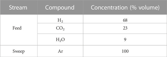
TABLE 1. Concentration values of the compounds used in the tests in the streams.
The separation factor between two compounds a and b (SFab) was experimentally calculated as the ratio of the partial pressure of those compounds in permeate and retentate according to Eq. 2.
where: pi is the partial pressure of compound i, Pa.
2.3 Experimental setup
The experimental system used to carry out the experiments consisted of the following components.
- High-pressure gas cylinders from which the gases used in the tests were fed. The gases fed from the bottles were: H2, CO2 and Ar. (Air liquid).
- Flow controllers that adjusted the flow of the different gases. (Brooks 5850 TR).
- HPLC pump that fed the flow of water used in the tests from the burette to the evaporator with the chosen flow. (Shimadzu LC10AT).
- Heating plate with a water evaporator to which the water was fed from a burette in the liquid state, and where the water was evaporated to feed it to the module in the vapor state. (Stuart CC162).
- Electrical resistances that preheated the gas mixture before feeding it to the reactor. These resistors wrapped the tubes through which the gases go to feed the module. The outlet tubes of the module were also heated to avoid condensation.
- Electric oven inside which was the membrane module, which maintained the necessary working temperature in the membrane.
- Membrane module: the membrane was placed inside. It had two inputs (feed and purge gas) and two outputs (retentate and permeate streams). The feed circulated in the internal side of the membrane, and the purge gas was fed through the exterior of the membrane, obtaining the permeate on the exterior side.
- Condensers at the outlet of the retentate and permeate streams that condensed the supplied water vapor, to subsequently measure the amounts of water in each stream.
- Back pressure controllers that maintained the pressure in the module at which the experiment is carried out (6, 16 and 26 bar). (Brooks SLA5800).
- Gas chromatograph that analyzed the concentrations of hydrogen and carbon dioxide in the two outlet streams. (Varian CP-3800).
3 Results and discussion
The experiments carried out consisted of introducing a stream of mixed gases through the interior of the membrane and a stream of argon through the exterior of the membrane as sweep gas. The gas feed included hydrogen, carbon dioxide and water steam. The ceramic support with the membrane is placed in a steel module that has two inputs and two outputs, for the input of feed and output of the retentate (inside the membrane) and sweep gas and permeate (outside the membrane).
The aforementioned streams were introduced in the tests, and the concentrations of the different gases at the outlet were measured both in the retentate and in the permeate with the gas chromatograph. In the case of water vapor, it condensed at the outlet of the two streams and the amount of condensed water (after c. a. 8 h of experiment) was weighed, to know the average concentration over the time of the experiment.
A series of tests were carried out with each synthesized membrane at different temperatures (160°C, 180°C and 200°C) and at different pressures (6, 16 and 26 bar), to determine the effect that these variables have on the separation of the introduced gases. The rest of the parameters used in the experiments were kept constant in order to see the effect of the other variables mentioned (pressure, temperature, number of layers, etc.).
Among the techniques used to prepare the polymeric membranes, the dip-coating technique provided the best results. Moreover, it was the one with the least reagent loss, since the amount of hydrogen and carbon dioxide that passes through is small, and the one that eliminated the greatest amount of water, thus achieving the desired objective of separation.
Another factor to consider is the quality of the prepared membrane. It was observed that the amount of polymer deposited on the ceramic support was not as important for performance as was the quality of the membrane (defined in terms of its homogeneity, absence of irregularities and/or deformations, as well as the permanence of its homogeneous appearance when subjected to the reaction conditions). This suggest that with a small amount of membrane imperfections (such as small open pores or pinholes), the gases (H2 and CO2) will easily pass through the membrane through the imperfections and this will reduce the separation of water from the gases.
The number of layers influenced the separation capacity of the membrane. Figure 1 shows the results with four membranes prepared with a different number of layers. Roughly speaking, the higher the number of layers, the higher the water vs gas separation factors obtained. This trend was expected since a new layer will cover the defects of the previous one, which leads to an improved selectivity. There was also a trend towards a decrease in the permeance of the compounds with the increase in the number of layers. This general trend may be expected, as a thicker membrane would have lower permeance. This trend did not strictly occur in all cases and tests carried out. This was because the quality of the synthesized membrane played a considerably more important role.
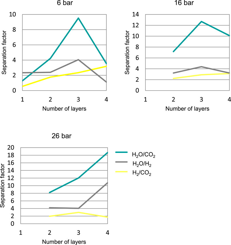
FIGURE 1. Separation factor, SFab at 160°C obtained with different membranes prepared by dip-coating, depending on the number of membrane layers, at different pressures.
The 4-layer membrane at low pressure did not give the expected separation results, obtaining worse separations at 6 bar than the 2- and 3-layer membranes. These poor results are probably due to a greater number of imperfections in the 4-layer membrane than in the other ones, causing the membrane to lose selectivity. The fact that the 3-layer and 4-layer membranes gave the best results led to more detailed studies being carried out with them, modifying the operating conditions (temperature and pressure).
Table 2 shows the variation in water permeance with the number of layers and the corresponding change in membrane thickness (calculated from the mass increase of the sample). In general, the higher the membrane thickness, the lower the water permeance, as may be expected if most water permeation occurs through the polymer and not through defects.
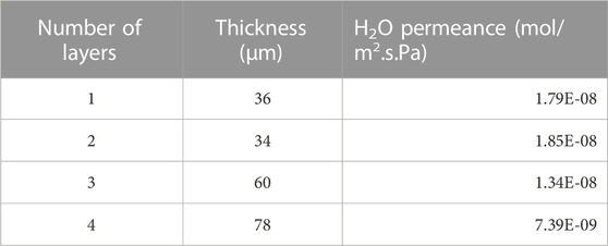
TABLE 2. Change in water permeance with the thickness of the membrane (160°C, 6 bar).
3.1 3-layer membrane
These membranes were prepared by the dip-coating method, depositing three times on the ceramic support. Figure 2 shows the evolution of the permeance of each compound with temperature at a pressure of 6 bar. It can be seen H2 and CO2 permeance increased with increasing temperature unlike the H2O permeance that decreases with increasing temperature.
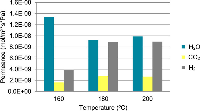
FIGURE 2. Permeance of the different compounds as a function of temperature at 6 bar.
The separation results as a function of temperature can be seen in Figure 3. In general, the separation factor of water (H2O/CO2 and H2O/H2) decreased as the temperature increased, although with a slight increase when going from 180°C to 200°C. This result may be explained by a decreased sorption of water in the intermolecular spaces of the polymer when the temperature was raised. The lower sorption of water would facilitate the diffusion of CO2 and H2, in a similar way as it was previously observed with microporous inorganic membranes (Gorbe et al., 2018). A quite surprising result is that the separation factor H2/CO2 increased with temperature in all the cases.
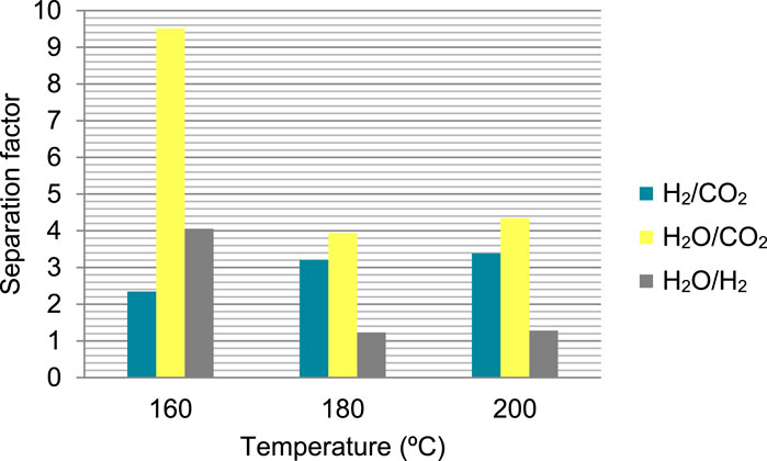
FIGURE 3. Separation factor, SFab as a function of temperature at 6 bar.
The evolution of the permeance with the working pressure is shown in Figure 4 for a temperature of 160°C. In the case of hydrogen and carbon dioxide, their permeance decreases as the pressure in the module increases, which suggest and increased blockage of pores by water adsorption. In the case of water, the effect of pressure was the same, the decrease in permeance with increasing pressure. This suggests that the solubility of water in the membrane does not increase linearly with the partial pressure of water above a certain value, which would correspond to a Langmuir-type adsorption isotherm.
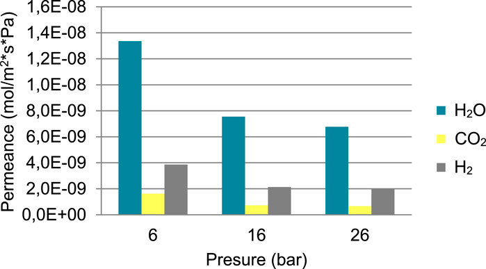
FIGURE 4. Permeance of the different compounds as a function of pressure, at 160°C.
The evolution of the separation factor of the different compounds as a function of the working pressure is shown in Figure 5. As can be seen in the graph, by increasing the pressure from 6 to 16 bar in the module, the separations H2O/H2 and H2O/CO2 increase. But going from 16 to 26 bar, the separations drop very slightly, which may be due to the fact that at such a high level of pressure the effect of membrane imperfections is amplified enough to favor the passage of gases over the passage of water.
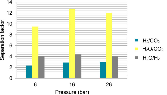
FIGURE 5. Separation factor, SFab of the gases analyzed as a function of pressure at 160°C.
3.2 4-layer membranes
Carrying out tests at a constant pressure and modifying the temperature (Figure 6), permeance increases with temperature. This increase occurs especially in the case of H2O.
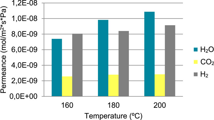
FIGURE 6. Permeance of the different compounds as a function of temperature at 6 bar.
Figure 7 shows the evolution of the separation factors with temperature. This evolution does not follow the same behavior as the rest of the analyzed membranes. In this case the separation factor of water versus permanent gases increased with increasing temperature, which is the opposite effect to that observed in all other membranes.
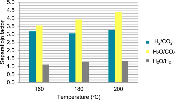
FIGURE 7. Separation factor, SFab of the gases analyzed as a function of temperature, at 6 bar.
The effect of pressure on permeance was roughly similar to the previous case, as shown in Figure 8. In the case of hydrogen and carbon dioxide, permeance decreased as the working pressure increased, while in the case of water, the permeance increased when going from 6 to 16 bar but it was smaller at 26 bar than at 16. An explanation for the decrease in the permeance of permanent gases is the increased occupation of the intermolecular spaces (between polymer chains) by water, which would decrease the available space for hydrogen or CO2 diffusion.
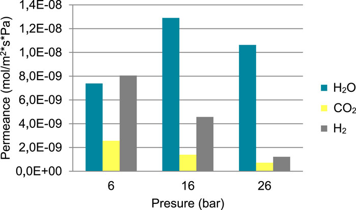
FIGURE 8. Permeance of the different compounds as a function of pressure at 160°C.
Figure 9 shows the evolution of the separation factors with pressure. This evolution followed the same trend as the 3-layer membrane, except for the H2/CO2 separation factor, that is, the separation increased with increasing working pressure. In this membrane, the highest values obtained for the separation of water with respect to gases can also be observed, obtaining higher separation values than the previous membrane.
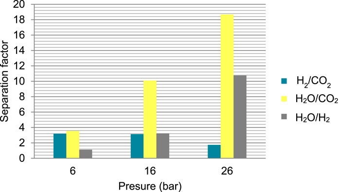
FIGURE 9. Separation factor, SFab of the gases analyzed as a function of pressure at 160°C.
4 Conclusion
A series of membranes were prepared by dip-coating, suction and emptying and external vacuum deposition techniques. The best results were obtained with the dip-coating technique. Membranes from 1 to 4 layers of polymer deposited on a ceramic support were prepared by this technique to see the effect that this variable had on the separation of reaction gases. Those prepared with 3 and 4 layers exhibited the best results.
In general, the membranes prepared with 3-layers performed better at low pressures while the 4-layers did better when working at high pressures.
It was found that, for 3-layer membranes, when the temperature was increased, the permeability increased for permanent gases but decreased for water. As a consequence, the water separation factor decreased significantly. For 4-layer membranes the water permeability also increased and, as a consequence, the H2O/CO2 separation factor increased slightly with temperature. The H2O/H2 separation increased slightly, but was near one at 6 bar at all the tested temperatures for this membrane.
The variation of the working pressure resulted in a decrease in the permeance of permanent gases and therefore an increase in the separation factor. This effect was more drastic for the 4-layer membrane, which provided the highest observed separation factors, at 26 bar and 160°C of 18.7 and 10.7 for H2O/CO2 and H2O/H2, respectively.
Data availability statement
The raw data supporting the conclusion of this article will be made available by the authors, without undue reservation.
Author contributions
IE: Validation, Writing–review and editing. JL: Validation, Writing–review and editing. JS: Conceptualization, Methodology, Writing–original draft. JH: Conceptualization, Methodology, Writing–original draft. MM: Conceptualization, Methodology, Supervision, Writing–review and editing.
Funding
The author(s) declare financial support was received for the research, authorship, and/or publication of this article. Authors gratefully acknowledge financial support from Agencia Española de Investigación (project PID 2019-106196RB-I00AEI/10.13039/501100011033).
Conflict of interest
The authors declare that the research was conducted in the absence of any commercial or financial relationships that could be construed as a potential conflict of interest.
Publisher’s note
All claims expressed in this article are solely those of the authors and do not necessarily represent those of their affiliated organizations, or those of the publisher, the editors and the reviewers. Any product that may be evaluated in this article, or claim that may be made by its manufacturer, is not guaranteed or endorsed by the publisher.
References
Barbieri, G., Marigliano, G., Golemme, G., and Drioli, E. (2002). Simulation of CO2 hydrogenation with CH3OH removal in a zeolite membrane reactor. Chem. Eng. J. 85 (1), 53–59. doi:10.1016/S1385-8947(01)00143-7
Bitter, J. H., and Tashvigh, A. A. (2022). Recent advances in polybenzimidazole membranes for hydrogen purification. Ind. Eng. Chem. Res. 61, 6125–6134. doi:10.1021/acs.iecr.2c00645
Cong, S., Wang, J., Wang, Z., and Liu, X. (2021). Polybenzimidazole (PBI) and benzimidazole-linked polymer (BILP) membranes. Green Chem. Eng. 2 (1), 44–56. doi:10.1016/j.gce.2020.11.007
Eguizábal, A., Lemus, J., Urbiztondo, M., Moschovi, A. M., Ntais, S., Soler, J., et al. (2011). Ammonium based ionic liquids immobilized in large pore zeolites: encapsulation procedures and proton conduction performance. J. Power Sources 196 (9), 4314–4323. doi:10.1016/j.jpowsour.2010.12.019
Farsi, M., and Jahanmiri, A. (2011). Application of water vapor and hydrogen-permselective membranes in an industrial fixed-bed reactor for large scale methanol production. Chem. Eng. Res. Des. 89 (12), 2728–2735. doi:10.1016/j.cherd.2011.05.012
Gallucci, F., Paturzo, L., and Basile, A. (2004). An experimental study of CO2 hydrogenation into methanol involving a zeolite membrane reactor. Chem. Eng. Process. 43 (8), 1029–1036. doi:10.1016/j.cep.2003.10.005
Gorbe, J., Lasobras, J., Francés, E., Herguido, J., Menéndez, M., Kumakiri, I., et al. (2018). Preliminary study on the feasibility of using a zeolite A membrane in a membrane reactor for methanol production. Sep. Purif. 200, 164–168. doi:10.1016/j.seppur.2018.02.036
Juarez, E., Lasobras, J., Soler, J., Herguido, J., and Menéndez, M. (2021). Polymer – ceramic composite membranes for water removal in membrane reactors. Membranes 11, 472. doi:10.3390/membranes11070472
Kamkeng, A. D. N., Wang, M., Hu, J., Du, W., and Qian, F. (2021). Transformation technologies for CO2 utilisation: current status, challenges and future prospects. Chem. Eng. J. 409, 128138. doi:10.1016/j.cej.2020.128138
Leonzio, G. (2018). State of art and perspectives about the production of methanol, dimethyl ether and syngas by carbon dioxide hydrogenation. J. CO2 Util. 27, 326–354. doi:10.1016/j.jcou.2018.08.005
Liu, G., Wei, W., Jin, W., and Xu, N. (2012). Polymer/ceramic composite membranes and their application in pervaporation process. Chin. J. Chem. Eng. 20 (1), 62–70. doi:10.1016/s1004-9541(12)60364-4
Menéndez, M., Piera, E., Coronas, J., and Santamaría, J. (1999). Reactor de membrana zeolítica para la obtención de metanol y otros alcoholes a partir de gas de síntesis. Madrid (Spain): Oficina Española de Patentes y Marcas. Spanish Patent No 2,164,544.
Olah, G. A. (2005). Beyond oil and gas: the methanol economy. Angew. Chem. Int. Ed. 44 (18), 2636–2639. doi:10.1002/anie.200462121
Sea, B., and Lee, K.-W. (2003). Methanol synthesis from carbon dioxide and hydrogen using a ceramic membrane reactor. React. Kinet. Catal. Lett. 80 (1), 33–38. doi:10.1023/A:1026015705619
Struis, R. P. W. J., and Stucki, S. (2001). Verification of the membrane reactor concept for the methanol synthesis. Appl. Catal. A Gen. 216 (1–2), 117–129. doi:10.1016/s0926-860x(01)00548-8
Struis, R. P. W. J., Stucki, S., and Wiedorn, M. (1996). A membrane reactor for methanol synthesis. J.Membr. Sci. 113 (1), 93–100. doi:10.1016/0376-7388(95)00222-7
Keywords: ceramic-polymer membranes, PBI membranes, membrane preparation, e-methanol synthesis, membrane reactors, CO2 use
Citation: Elvira I, Lasobras J, Soler J, Herguido J and Menéndez M (2023) Preparation of polymeric-ceramic composite membranes for use in the methanol synthesis reaction. Front. Membr. Sci. Technol. 2:1267374. doi: 10.3389/frmst.2023.1267374
Received: 26 July 2023; Accepted: 10 October 2023;
Published: 26 October 2023.
Edited by:
Andreas Sapalidis, National Centre of Scientific Research Demokritos, GreeceReviewed by:
Giuseppe Barbieri, National Research Council (CNR), ItalyDavid Alfredo Pacheco Tanaka, Tecnalia Research & Innovation, Spain
Copyright © 2023 Elvira, Lasobras, Soler, Herguido and Menéndez. This is an open-access article distributed under the terms of the Creative Commons Attribution License (CC BY). The use, distribution or reproduction in other forums is permitted, provided the original author(s) and the copyright owner(s) are credited and that the original publication in this journal is cited, in accordance with accepted academic practice. No use, distribution or reproduction is permitted which does not comply with these terms.
*Correspondence: M. Menéndez, bWlndWVsLm1lbmVuZGV6QHVuaXphci5lcw==