 Samer Alfayad1*
 Mohamad El Asswad1
 A. Abdellatif1
 Fethi B. Ouezdou1
 Arnaud Blanchard2
 Nils Beaussé2
 Philippe Gaussier2
- 1Laboratoire d’Ingénierie des Systèmes de Versailles (LISV), EA4048 Université de Versailles Saint-Quentin-en-Yvelines, Paris-Saclay University, Vélizy, France
- 2Equipes Traitement de l’Information et Systèmes (ETIS), UMR 8051/École Nationale Supérieure de l’Electronique et de ses Applications (ENSEA), University of Cergy-Pontoise, CNRS, Cergy-Pontoise, France
In the framework of the HYDROïD humanoid robot project, this paper describes the modeling and design of an electrically actuated head mechanism. Perception and emotion capabilities are considered in the design process. Since HYDROïD humanoid robot is hydraulically actuated, the choice of electrical actuation for the head mechanism addressed in this paper is justified. Considering perception and emotion capabilities leads to a total number of 15 degrees of freedom for the head mechanism, which are split into four main sub-mechanisms: the neck, the mouth, the eyes, and the eyebrows. Biological data and kinematics performances of human head are taken as inputs of the design process. A new solution of uncoupled eyes is developed to possibly address the master-slave process that links the human eyes as well as vergence capabilities. Modeling each sub-system is carried out in order to get equations of motion, their frequency responses, and their transfer functions. The neck pitch rotation is given as a study example. Then, the head mechanism performances are presented through a comparison between model and experimental results validating the hardware capabilities. Finally, the head mechanism is integrated on the HYDROïD upper-body. An object tracking experiment coupled with emotional expressions is carried out to validate the synchronization of the eye rotations with the body motions.
1. Introduction
The design of a humanoid robot capable of interacting with humans and the environment is still a challenging problem. This leads to the development of a wide variety of full size humanoid prototypes, such as ASIMO (Hirai et al., 1998), WABIAN (Ogura et al., 2006), HRP-4 (Kaneko et al., 2011), ATLAS (Banerjee et al., 2015), and the underdevelopment HYDROïD (Alfayad, 2011). Such prototypes offer several capabilities to ensure physical interaction with the environment through either manipulating objects or walking in a domestic environment.
Some other small size humanoid robots are dedicated to entertainment or educational and research applications. In this class of humanoid robots, the main ones are NAO (Gouaillier et al., 2009), DARwIn-OP (Ha et al., 2011), and NimbRo-OP (Schwarz et al., 2013). The last class of humanoid robots deals with the middle size prototypes, such as iCub (Beira et al., 2006) and Poppy (Lapeyre et al., 2013).
The three classes of humanoid robots given before exhibit perception capabilities, mostly based on vision to ensure the recognition of the environment as well as the tracking of human face. Providing emotional and friendly reactions like a human being is still an open question in the design of humanoid robot heads. Some prototypes offer emotional capabilities based on more or less complex mechanisms, such as WE-4RII (Arent et al., 2008), Kismet (Breazeal, 2003), NEXI (Delaunay et al., 2009), ROMAN (Hirth et al., 2007), and FLOBI (Lutkebohle et al., 2010). When starting designing a humanoid robot head, two main choices are offered. Indeed, one aims to get a robotic head as a “copy” of a human head. The other aims to get a more optimized technical mechanism (a technomorphic head).
The advantage of a technomorphic head is that there is no restriction in design parameters, such as head size or shape. This option greatly reduces the effort for the mechanical design. On the other hand, human-like heads need realistic facial expressions to support communication between a robot and the human. This inherently leads to complex mechanisms to reproduce emotional capabilities.
Another challenge in the design of humanoid heads deals with the choice of sub-mechanisms in order to reach acceptable perception and emotional capabilities. Analyzing main functional components present in the human head leads us to identify four main sub-parts that are the neck, the eyes, the eyebrows, and the mouth. The two first sub-parts are required to perception capabilities, while the two last are necessary to display some facial expressions. This decomposition was clearly adopted in ARMAR III (Asfour et al., 2008), iCub, FLOBI, WE-4RII, Kismet, and Nexi prototypes.
Moreover, almost all existing robotic head prototypes are based on electrical actuation. This choice is mainly due to the low cost, easiness in usage, and control contrary to hydraulic or pneumatic actuation. Such features make electric actuation the most suitable technology as stated by Arent et al. (2008).
Since our aim behind the HYDROïD robot is to have a fully functional hydraulic humanoid robot, the choice of the kind of actuation of the proposed robotic head has to be justified. The main advantage of developing HYDROïD humanoid robot is to have one of the first hydraulic integrated humanoid robot with the ability to transfer the hydraulic power without the need of hydraulic pipes (Alfayad, 2009). Hence, the first choice may be based on hydraulic actuation even for the head. Nevertheless, the required power to actuate the four sub-parts already mentioned above does not justify the use of hydraulic transmission since this would inherently lead to a complex technomorphic head. Moreover, careful analysis of possible use cases of robotic head leads us to the idea of developing a new humanoid head that can be used either as a necessary sub-mechanism to complete HYDROïD humanoid robot or as a separate test bed for research on human interaction through perception and emotion capabilities. The last will be called desk version of the addressed head prototype.
Finally, the eye mechanisms of almost all other head prototypes are based on coupled eyes. The concept of uncoupled eye mechanism was first introduced by Ouezdou et al. (2006). Such functionality ensures the vergence capability present in the human vision system, which allows the two eyes to concentrate on the same point in the space. This makes the proposed head prototype a suitable test bed for studying strabismus and ametropia (especially with children) (Puig et al., 2002). Moreover, it will allow to possibly address the eyes master-slave control process used by humans.
The paper is organized as follows. At first, a bio-mechanical study of the human head mechanisms is detailed in Section 2. This leads us to carry out a detailed mathematical model for the head subsystem in Section 3. Then, the mathematical model analysis is detailed in Section 5 to identify system natural frequencies. Section 4 deals with the estimation of mass and inertia of the whole mechanism, which is needed for the positional control of the different joints of the mechanism presented in Section 6. Meanwhile, the mechanical design is discussed in Section 7. Then, an experimental evaluation of the proposed robotic head mechanism is shown in Section 8. A visual tracking experiment of a moving target is shown in sub-section 8.2, while basic expressive capabilities were demonstrated in sub-section 8.3. Finally, the conclusion and the future works are presented in Section 9.
2. Head Bio-Mechanical Study
To be able to design a humanoid head mechanism, the specifications of a human head should be identified. These specifications deal with dimensions, rotation ranges, and motion speeds. Therefore, a bio-mechanical study should be carried out in order to specify the inputs of the mechanical design process. The analysis focuses on the main parts of the human head (neck, eye, and mouth), which are detailed in the following three main sub-sections: 2.1, 2.2, and 2.3.
To describe the human head correctly, the head length, width, circumferences, the eyes dimensions, the eyes separating distance, and the mouth dimensions have to be known. The human head has an average length that varies from 19.5 to 23.3 cm with an average width varying from 15.4 to 15.9 cm. The circumference varies from 56.5 to 58.5 cm. The human head has an average height, excluding the neck, varying from 22.3 to 23.3 cm as stated by Haley (1988).
2.1. Human Neck Bio-Mechanical Study
The average human neck dimensions are stated by Haley (1988), where the average neck circumference varies from 36.5 to 40.6 cm. Meanwhile, the average neck length varies from 8.3 to 8.5 cm. The human neck motions include flexion/extension (pitch rotation), the vertical rotation (yaw rotation), and the lateral bending (roll rotation) (Fitzpatrick, 2010). The flexion movement with a canonical range of 50° allows the head to bend toward the chest, while the extension with a range of 57.5° ensures the head to tilt back. These two motions can be considered as the lower pitch rotation of the neck. The vertical neck rotation is described as turning motion of the head to the right and to the left. The range of rotation is 70°, starting from the main head axis. This motion can be considered as the yaw rotation of the neck. The lateral bending is the motion that allows the head to bend toward the shoulder. The bending angle of motion is 45°. This is called the roll rotation. All of these motions are shown in Figure 1.
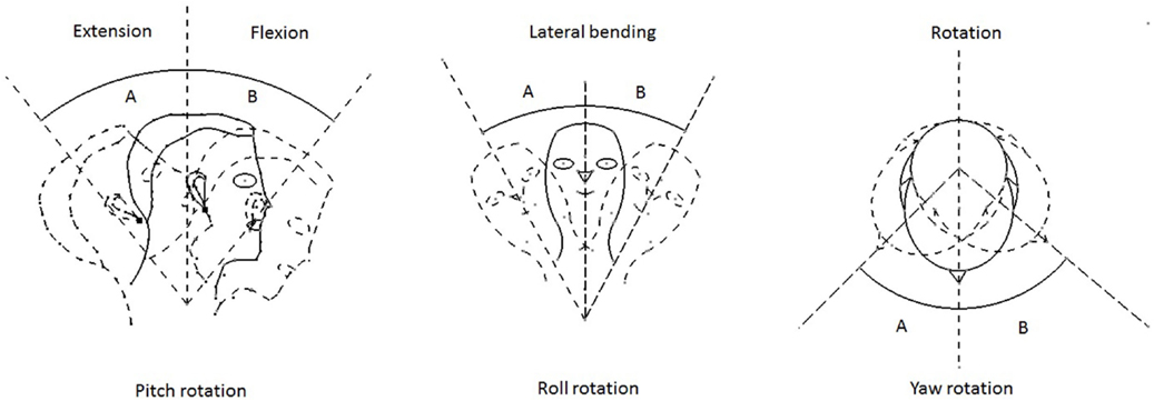
Figure 1. Human neck motions.
To complete the mechanical design, the speed specifications for each joint have to be fixed. As stated by Fitzpatrick (2010), the neck velocities reach a maximum value of 360°/s for the roll rotation, 430°/s for the pitch rotation, and 467°/s for the yaw rotation.
2.2. Human Eye Bio-Mechanical Study
The average eye dimensions differ according to the human age (Gross et al., 2008). At the age of 13 years, the eyeball reaches its full size diameter of 24 mm. The inter-pupillary distance (IPD) (which is the distance between the centers of the two pupils) has an average range of 56 to 72 mm. The pupil diameter has an average range of 2 to 8mm. Also, it is known that the eye performs approximately a range of motion of 35° up and down, to the right and to the left.
Jacob (1993) stated that the eye performs sudden and rapid motion called saccades. It moves with 1–40° in 30–120 ms. Then, this is followed by a period of stability called fixation, needed to recognize the objects. This period is estimated by 200–600 ms.
The approximate field of view of the eye is as shown in Figure 2, with 105° away from the nose, 85° downward, 70° toward the nose, and 50° upward. The total forward field of view of the human eye, with the movement of the neck, is almost 180°(Fitzpatrick, 2010).
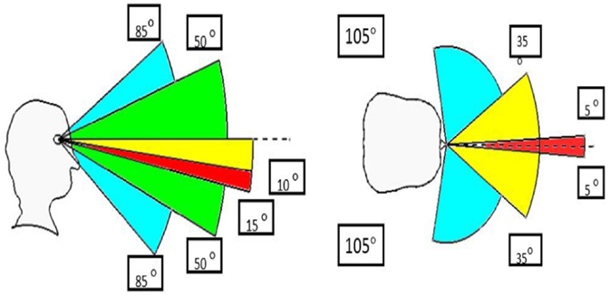
Figure 2. Eyes fields of view.
For the eye movements, a maximum angular velocity of 570°/s for yaw and pitch movements can be observed.
2.3. Human Mouth Bio-Mechanical Study
The average human mouth considered at the maximum opening has a value of 57.2 mm (Fitzpatrick, 2010). The human mouth consists of two lips that represent its movements. The movements of the upper and the lower lips of the mouth give the different facial expressions. The mouth motion includes the jaw and the lips motions. The jaw motion differs according to the human age and gender. For the lips motion, it differs according to the facial expressions. Meanwhile, the mouth motion reaches a maximum velocity of 286 mm/s.
3. Mathematical Model of the Head Mechanism
The aim of this section is to establish the system mathematical model in order to get the equation of motion, the frequency response, and the transfer function. Through the bio-mechanical analysis carried out in the previous section, the total number of degrees of freedom (DOF) taken in consideration is 15. These DOF are split over the four sub-parts as follows: three DOF for the neck; two independent DOF for each eye, and five DOF for the mouth mechanism. Finally, each eyebrow has two DOF independently and one DOF in common between the two eyebrows. There are similarities between the pitch and yaw movements of the neck and the eyes. Hence, to avoid repetition, the neck pitch movement is given in detail in the following, while only the final result for neck yaw is presented. The equations of motion as well as the transfer functions of the eye movement can be also deduced from the neck ones thanks to the similarities mentioned above. Due to the need of power, the mouth and the eyebrows are actuated by servos, with a very small range of motion. Thus, it is not necessary to carry out the modeling of those two sub-systems as there is no need for a detailed transfer function.
To establish the mathematical model for the pitch movement, both neck and eye sub-systems can be modeled as an inverted pendulum as depicted on Figure 3. An elastic element (i.e., a transmission belt) with a given stiffness is considered between the input electric motor and the corresponding head block that represents all parts of the considered sub-mechanism.
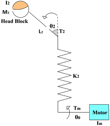
Figure 3. Adopted model for pitch rotation.
First of all, we have to consider the two following dynamic equations on the motor axis:
where the acceleration of the motor is denoted as ; is the acceleration of the subsystem; Tm is the motor torque; T2 is the applied torque on the subsystem; k2 is the stiffness of the belt; θ0 is the angular position of the motor; θ2 is the angular position of the subsystem; Im is the moment of inertia of the motor; I2 is moment of inertia of the subsystem, and M2 is the mass of the subsystem.
Let n2 be the reduction ratio between the motor axis and the output axis,
For the term sinθ, Taylor expansion is consider for small angles, and sinθ can be approximated to For simplicity, only the first term is taken into account.
By combining the previous equations, the two following relations can be deduced:
By equating the two previous relations and considering the relation between the output system torque T2 and the input motor torque Tm (T2 = μn2Tm with μ the efficiency coefficient of the belt), the following θ2 expression can be established:
Equation (7) can be generalized to obtain the transfer functions of all the other DOFs of the head, namely yaw and roll of the neck sub-mechanism and pitch and yaw of the eyes. For the yaw rotations (neck and eye sub-mechanisms), there is no effect of gravity and the corresponding term in equation (7) has to be avoided. Consequently, the yaw motion transfer function of the neck can be established as follows:
where Im is the motor moment of inertia; I1 is the yaw sub-system moment of inertia; Tm is the input torque; θ1 is the neck yaw angle; k1 is the stiffness of the flexible element, and μ its corresponding efficiency coefficient.
The above established equations (7) and (8) will be used to carry out, respectively, the position control of the neck pitch and yaw rotations, as it will be shown in Section 6.
4. Mechanism Parameters Estimation
Thanks to the bio-mechanical analysis, HYDROïD head will have a weight of about 1.7 kg and a total number of 15 DOF. The total mass of the head, including the neck is distributed into its four main parts, where the neck weighs 1 kg, the eyes weigh 0.35 kg, the mouth weighs 0.175 kg, and the eyebrows weigh 0.175 kg. All these values include the electronics and motors masses. The moments of inertia of the neck are estimated to: 4 gm2 around the yaw axis; 1 gm2 around the pitch axis, and 2 gm2 around the roll one. For the eyes, the moment of inertia is equal to 0.06 gm2 around the yaw axis and 0.04 gm2 around the pitch one. For the mouth, it equals to 0.3 gm2 around the roll axis, while the eyebrows have a moment of inertia of 0.1 gm2 around the considered axis of movement.
To actuate the total 15 DOF, electric motors were chosen. This choice is motivated by the required powers for all joints that are quite small. Moreover, the hydraulic actuation will inherently lead to complex mechanisms that will bring drawbacks without any benefit in this case (reduced required power). Hence, for the neck, an EC 20 flat brushless motor of 5 W with integrated electronics, a nominal torque of 0.0075 N⋅m, a nominal speed of 6000 rpm, a gear ratio of 128:1 with a mass of 37 g is chosen for each rotation. For the eye yaw and pitch rotations, an Athlonix 12G88 motor is selected with a nominal torque of 0.00368 N m, a nominal speed of 8670 rpm, a stall torque 0.0068 N⋅m, 2.5 W as an output power, and a total mass of 15 g. For the mouth as well as for the eyebrows, GWS Naro servomotors are chosen with a range of motion of 180°, a torque of 0.12 N m, and a mass of 8.8 g.
5. Model Analysis
The head mechanism system has to achieve accurate motion. The vibration response may need to be modified in order to bring the overall system response within acceptable range, mainly when achieving perception capabilities, such as position tracking as will be discussed in Section 6. Hence, in order to apply the needed vibration analysis, the natural frequency of the system has to be identified. This will allow us, for instance, to avoid resonance phenomena. Hence, the input frequency of the system must be lower than its natural frequency to avoid resonance and phase shift. Although if the input frequency is higher than the natural frequency, resonance is avoided, but the system will have no time to reach its full bandwidth. Once again, the model analysis will be detailed only for the pitch motion of the neck in the following subsection. The same analysis was carried out for yaw motion of the neck sub-mechanism and for yaw and pitch motions of the eyes.
5.1. Natural Frequency of Pitch Rotation of Neck Subsystem ωnp
For the pitch rotation movement, the equations describing such system of the neck up right position (α = 0) were already given in the previous section [see equations (1) and (2)]. To start the vibration analysis, let us assume sinusoidal function of time for the input θ0:
In this case, the output θ2 can be also written as sinusoidal function of time as following:
Therefore, by substituting θ0 and θ2 in equations (1) and (2), the following two relations can be established:
Thus, the previous system of equations can be written in a matrix form as following:
The natural frequency ωnp for this subsystem is a solution of nullifying the determinant of the previous system of equations as can be expressed in the following form:
This leads to the following four order polynomial equation in ωnp:
Knowing that Im (motor inertia) is much smaller than I2, the last equation can be simplified as following:
This new equation [equation (16)] is solved using quadratic formula and only positive solutions are considered. Thus, the natural frequency ωnp is calculated by the following expression:
where and
The same methodology is used to get the natural frequency of the yaw rotation ωny. In this case, the gravity effects have to be removed from equation (16) while using the corresponding parameters. The equation becomes simpler and the natural frequency ωny is the following:
5.2. Effects of Input Frequency on the Head Rotation
It is well known that the frequency applied on the system, denoted Ω, should avoid the value of the natural frequencies ωny and ωnp. This is because of the resonance phenomena (Rao, 2003) that may make the system malfunctioning. Hence, the applied frequency Ω should be chosen higher or lower than the natural frequency. Nevertheless, thanks to the established mathematical model, we observe that increasing the value of the applied frequency leads to a drastically decreasing of the motion bandwidth. Hence, this leads to undesirable rotations of the neck in pitch and yaw directions. The values of the natural frequencies were estimated thanks to the mathematical model and an estimation parameters of the neck mechanism based on bio-mechanical data is given in Section 4. The simulated results for the neck lead to ωny = 62.6 rad/s for the yaw rotation and ωnp = 4.5 rad/s for the pitch one. Moreover, the eyes natural frequencies are estimated to ωey = 20 rad/s for the yaw rotation and to ωep = 18 rad/s for the pitch motion.
Figure 4A shows that by increasing the value of the applied Ω, the bandwidth of motion decreases. As a result, the range of applicable Ωy for the yaw rotation is between 0 and 10 rad/s as shown in Figure 4B. For the pitch rotation, the range of applicable Ωp is between 0 and 4 rad/s.
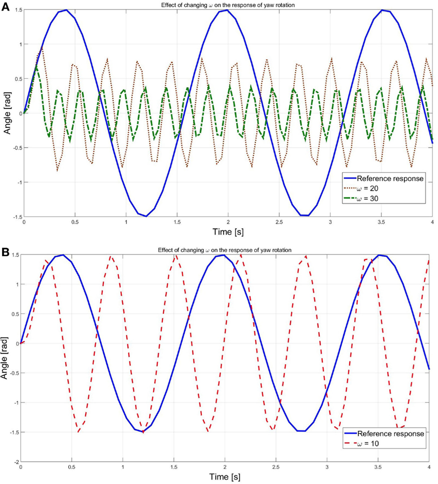
Figure 4. Effect of input frequency on the neck yaw rotation response. (A) the output response for the undesired frequencies (Ωp = 20 and Ωp = 30) (in green and in orange) is compared to the desired response (in blue). (B) the output response for the accepted frequency (Ωp = 10)(in red) is compared to the desired response (in blue).
6. Position Control Algorithm
In order to check the position response of the proposed head mechanism, the transfer functions already determined in Section 3 are used. These functions are included in a simulated model based on MATLAB-Simulink as shown in Figure 5. For the neck mechanism, the reference θ1 for yaw and θ2 for pitch are simulated as an input sine wave of frequency value equals to 1.5 rad/s for the yaw motion and to 1 rad/s for the pitch one. These values are chosen in the range of the acceptable frequencies calculated in the previous Section 5. Therefore, vibration effects disturbing the response are avoided.
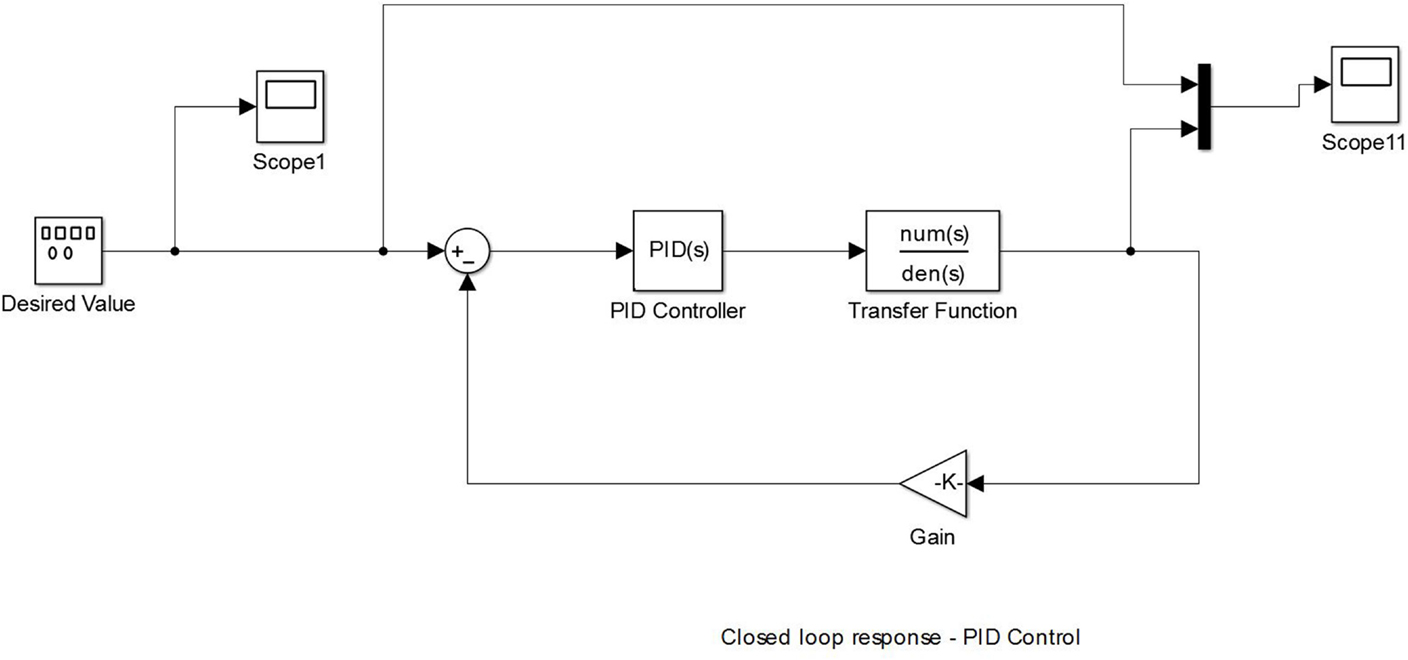
Figure 5. Simulation model for the pitch rotation mechanism with a PID control using the calculated transfer function.
The simulated results for the neck movements are detailed in the following sub-sections. The aim of the carried simulation is to determine the appropriate PID gains to apply to the mechanism.
6.1. Position Control for Yaw Neck’s Motion
The open loop response of the rotation in the yaw direction is shown in Figure 6A. A noticeable error between the desired and the simulated responses is pointed out.
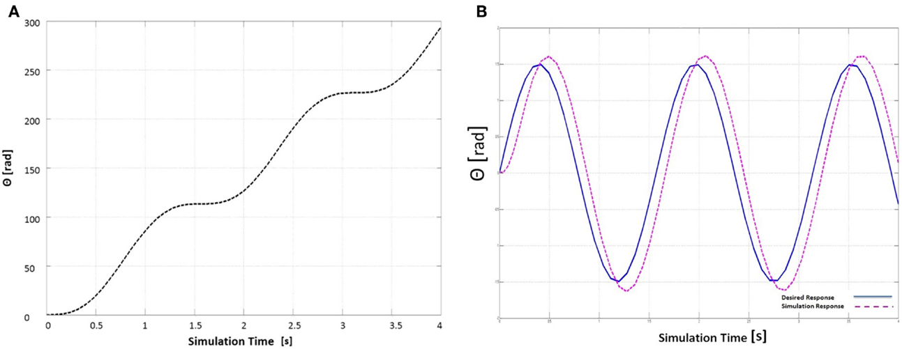
Figure 6. Yaw neck’s rotation with (A) open loop response of the simulated position tracking and (B) closed loop with applied PID gains.
A closed loop is added to the model and a sinusoidal input having an amplitude of 1.5 rad is applied to the system. The simulated response shows a delay in rise time equals to 0.126 s, while an error in settling time equals to 1.84 s and an overshoot error equals to 12.6 rad with a slight oscillation at the signal peak are observed. These results are shown on Figure 6B. The controller gains were deduced using Ziegler–Nichols tuning method (Meshram and Kanojiya, 2012). The suitable gains for such model are found to be Kp = 0.0476, Ki = 0.0786, and Kd = 1.1546.
6.2. Position Control for Pitch Neck’s Rotation
As shown in Figure 7A, the open loop response of the rotation in the yaw direction indicates a noticeable error between the desired and the simulated responses.
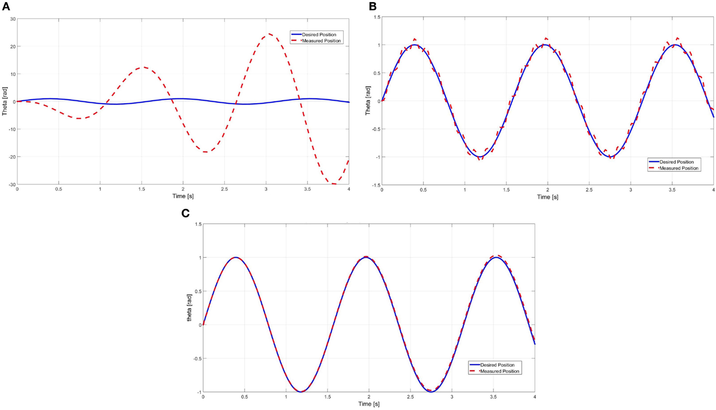
Figure 7. Pitch neck’s rotation with (A) open loop response simulated position tracking, (B) closed loop with applied unity feedback gains, and (C) closed loop response with applied PID gains.
As previously mentioned, a closed loop is added to the model with unity feedback as shown in Figure 7B. Simulated response showed a delay in rise time equals to 0.1181 s, an error in settling time equals to 0.0484 s and an overshoot error equals to 0.3 rad with a slight oscillation at the signal peak. The position PID controller added on the model leads to the results shown in Figure 7C. This controller gains are deduced using Ziegler–Nichols tuning method reaching the following suitable gains: Kp = 0.296, Ki = 0.021, and Kd = 5.431.
The new response of motion is shown in Figure 7C leading to a significant decrease of rise time to 0.0024 s. Settling time had a slight decrease to reach 0.1557 s and with almost no overshoot and no un-damped oscillations.
Thanks to the simulated results based on the mathematical model, the estimated parameter values were determined. These values are considered as the input of the mechanical design process that is detailed in the following section.
7. Mechanical Design of the Head Mechanism
The mechanical design of the HYDROïD head mechanism has taken several criteria in consideration, such as the number of degrees of freedom of each subsystem; the range of motion; the joint velocities, and the required torques. Such parameters have been taken either from the previously mentioned bio-mechanical study in Section 2 or as a result from the simulated models described in the previous section. Moreover, the simplicity, compactness, and the easiness in installation on the HYDROïD upper-body were taken into account during the design process. We focus on the novelty aspect by considering an uncoupled eyes mechanism. This aspect makes HYDROïD head mechanism unique regards the other humanoid heads while vision based perception capabilities are considered. Figures 8 and 9 shows an overview of the proposed HYDROïD head mechanism and its several sub-parts.
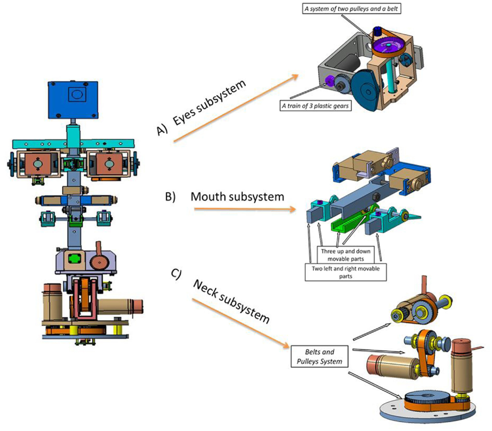
Figure 8. Design of the HYDROïD head mechanism and main sub-parts: (A) Eye subsystem, (B) Mouth subsystem and (C) Neck subsystem.
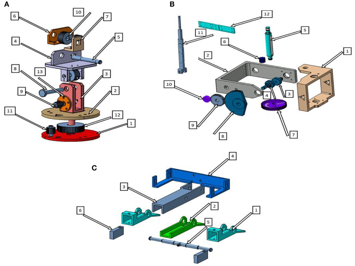
Figure 9. Exploded view with numbering parts of HYDROïD’s head: (A) neck sub-system, (B) eye sub-system, and (C) mouth sub-system.
7.1. Neck Mechanism
For HYDROïD’s head, a serial neck mechanism is built with three DOF as can be seen in Figure 8C. The serial mechanism is a simple, robust, and easily controlled configuration in comparison to the parallel one. The parallel mechanism is usually used when high load capacity is required, which is not needed for our case. Moreover, the main disadvantage of the parallel mechanism is the interference between the various parts especially when small space is allowed (Beira et al., 2006).
The neck mechanism is formed from three pulley and a belt systems shown in Figure 8C. The use of belts and pulleys allows us distant transmission in any direction. Belts are cheap for small systems; have a unique ability for vibration isolation. In addition to this advantage, belt transmission systems avoid what the gear trains induce, such as backlash, noise, and vibration. The latter needs a specific material and coating, from which the gear has to be manufactured from. Another mechanical option to be used is the mechanical chain. But due to its high mass and instability of velocity (cordial effect) which causes vibration, noise, and limitation in position, the mechanical chain was not selected in the proposed mechanism. Nevertheless, the use of timing belts allows us to avoid slipping. The detailed mechanical components for this sub-system is mentioned in Table 1.
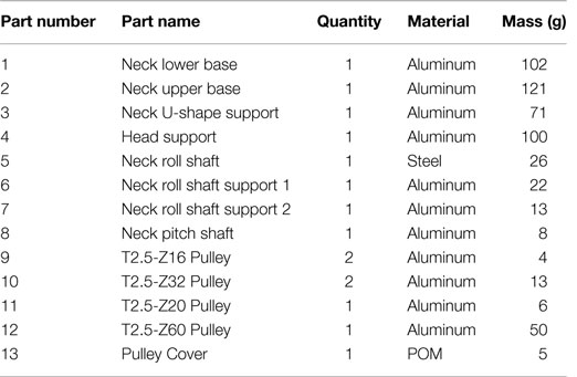
Table 1. Neck sub-system list of parts with quantities, materials, and masses (see Figure 9A).
7.2. Mouth Mechanism
There are five integrated degrees of freedom decomposed as following. Three of them allow pitch rotations and the two others reproduce yaw motions. The mouth is formed of five movable parts with three rotation axes as shown in Figure 8B. Three parts move up and down around the pitch rotation axis and two separate parts are rotating in yaw direction. A spring connects the five points together, to mimic the human mouth motion. The used mechanism for rotation is connected to the motor shaft by means of a metallic wire. The detailed mechanical components for this sub-system are mentioned in Table 2.
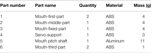
Table 2. Mouth sub-system list of parts with quantities, materials, and masses (see Figure 9C).
7.3. The Uncoupled Eyes Mechanism
The eye mechanism has two DOF. The yaw rotation is driven by a belt and pulley system, while the pitch moment is insured by train of gears. Small gears were used instead of the pulleys/belt to avoid the limitation of the eyes field of view. Moreover, the largest gear is chopped as shown in Figure 8A in order to increase the vision perception capabilities. The detailed mechanical components list, the used materials, and the part masses are given in Table 3.
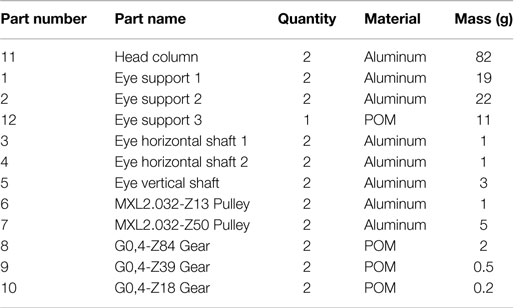
Table 3. Eye sub-system list of parts with quantities, materials, and masses (See Figure 9B).
HYDROïD head eyes are able to move independently to each other. This provides the vergence capability that exists in the human visual system. The vergence capability allows eyes to focus on a same point in space. This capability is needed for tracking target movement that is a main objective of the developed prototype and will be shown experimentally in Section 8.2. Moreover, this novel peculiarity of the proposed head allows the medical study of human visual system disorders, such as Strabismus, which is a condition that interferes with binocular vision because it prevents a person from directing both eyes simultaneously toward the same fixation point as stated by Puig et al. (2002).
7.4. Eyebrows Mechanism
To enhance the emotion capabilities of the HYDROïD’s head, an eyebrow mechanism is included in the design. Our aim is to make HYDROïD’s head showing emotional performances with the simplest mechanism. The single eyebrow is formed from two plastic parts that can move up and down. Each part is actuated by a servo motor connected to a rotation axis in roll direction. This allows us to create the inverted V-shaped expression of the human eyebrows. Moreover, the two eyebrows are connected to one axis in the pitch direction.
8. Experimental Results
The assembled prototype of the proposed HYDROïD’s head is shown with two versions on Figure 10. The left part of the figure shows the head mechanism mounted on the upper body of HYDROïD humanoid robot while the right one shows the standalone desk version during experimental tests. In the following subsections, experimental results with both prototypes will be detailed. The aim of the experiments carried out is to determine the performances of the head mechanism and demonstrate its perception and emotion capabilities.
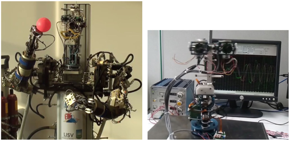
Figure 10. The HYDROïD head mechanism assembled on the upper body (left) and desk version (right).
8.1. Neck’s Yaw, Pitch, and Roll Motions
Several experimental tests are carried out thanks to the head prototype desk version (Figure 10 Right). The first set of validation tests deals with the range limits of all the movements and the maximum velocity performances that can be reached by the neck and eye joints. The range limits are shown on Figure 11 where the roll movement is given on A and B subfigures, pitch rotation on C and D and finally yaw motion limits on E and F. The limits of range of motion and the maximum velocities measured experimentally are given in Table 4.
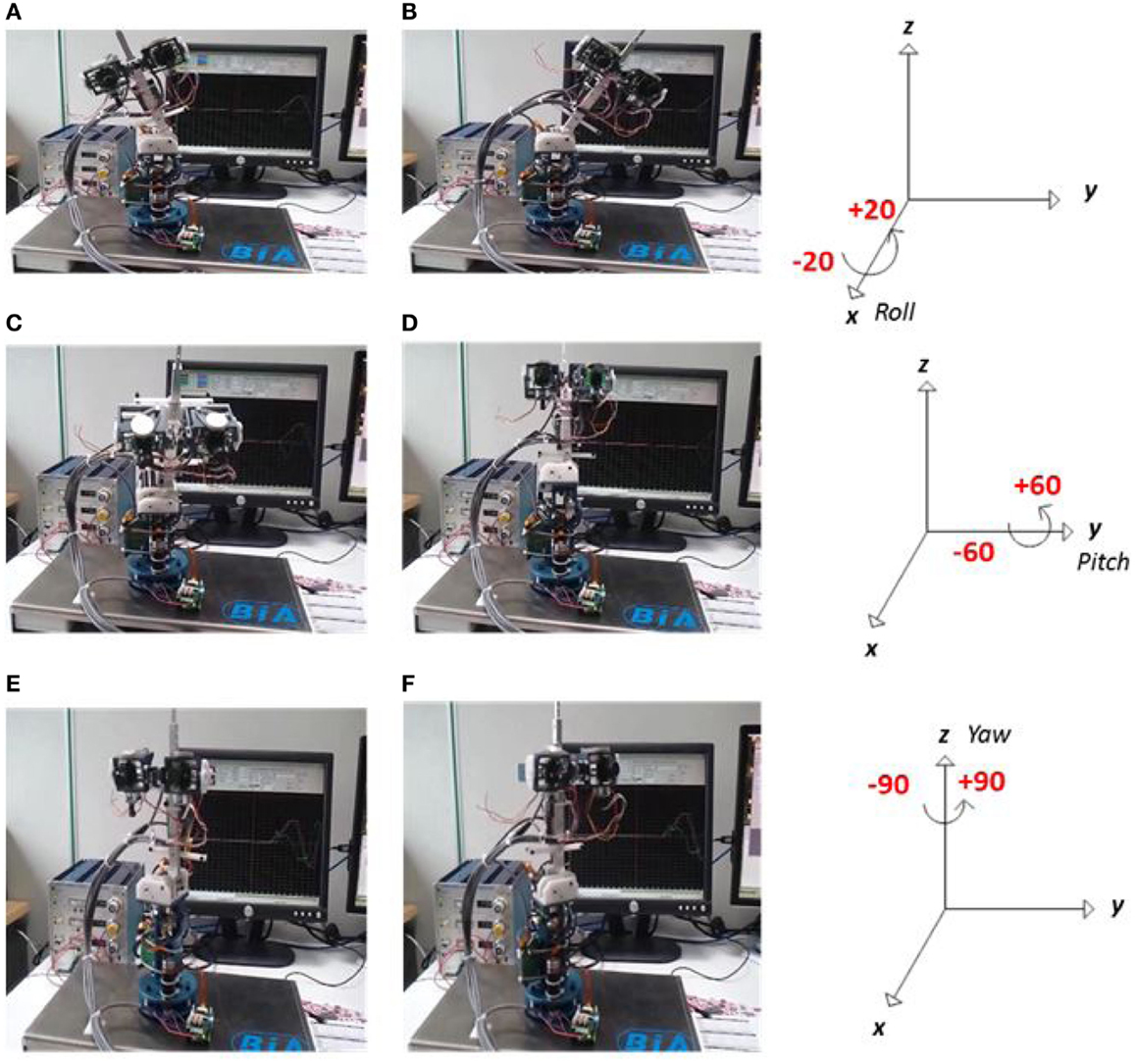
Figure 11. Neck rotation motions of the HYDROïD head mechanism: pitch (A,B), yaw (C,D), and roll (E,F).
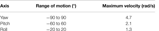
Table 4. Rotation, motion ranges, and maximum velocities for the neck mechanism.
On the other hand, the responses of neck pitch and yaw rotations are validated using a position control algorithm. The comparison with the simulated responses is detailed in Figures 12A,B where sinusoidal and square input functions are applied to the assembled prototype. Figure 12A shows the response of the yaw movement for a sine function with maximal amplitude of θ = 30° and a frequency of 0.63 rad/s. These values were chosen according to the capabilities of the human neck’s yaw movement as stated by Fitzpatrick (2010). As a result, a slightly minimal error between the simulated model and the experimental response of the prototype can be noticed. Moreover, the experimental response follows the simulated one with no overshoot or steady state error. Nevertheless, there is a delay of the hardware response with a difference in settling time of 0.8 s.
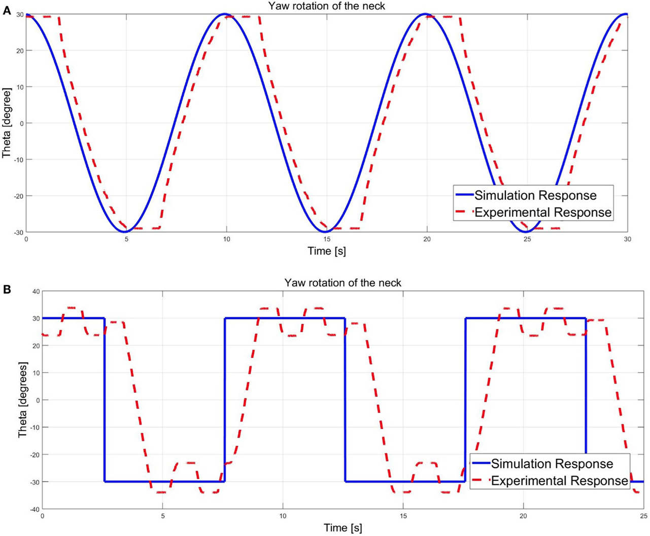
Figure 12. Experimental simulation comparison of the yaw rotation of the neck with (A) sine input θ = 30° and (B) square input θ = 30°.
On the other hand, a square input with a maximum amplitude of θ = 30° is applied to the desk version. The response of yaw rotation of the neck mechanism to this function shows an oscillation (see Figure 12B). An overshoot of 4.7 rad is also noticed when the simulated and the experimental results are compared. This overshoot indicates that the damping of the sub-system has to be slightly increased.
8.2. Object Tracking Experiment
The second set of experiments deals with the vision based perception capabilities of HYDROïD head mechanism. In this case, a version of the head mechanism is mounted on the humanoid HYDROïD upper body with two hydraulic arms (See Figure 10 Left). The objective is to show the synchronization between the movements of the head (neck and eye) and the right arm that grasp a colored ball. Moreover, the goal of this experiment is to produce saccadic eye movements or smooth pursuit as human are able to do. Hence, the eye and neck rotations are combined in an object tracking experiment to follow a ball grasped by the hydraulic arm. Then, the response of the eye yaw rotation is tested through a square input function. The comparison results are depicted on Figure 13.
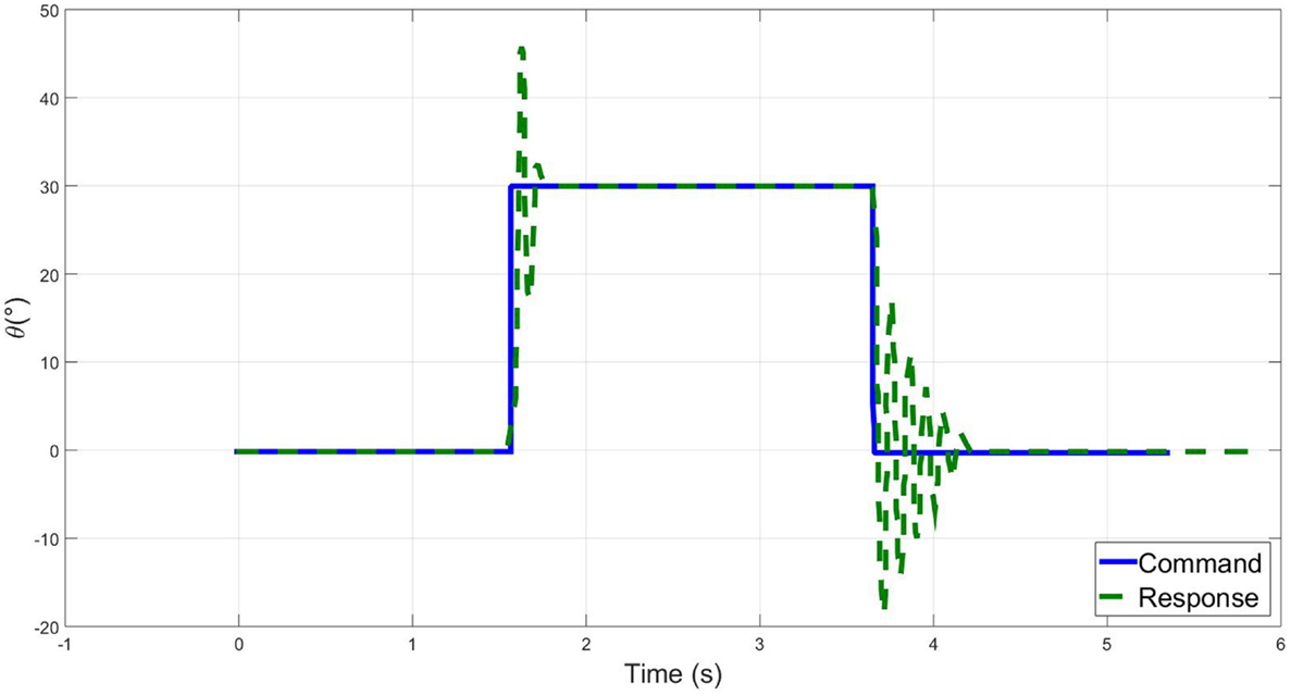
Figure 13. Eye yaw rotation response (in green) is compared to a square command input (in blue).
The main difficulty in visual tracking of moving targets is related to the delay since the sampling rate of the proprioception is at 1000 Hz and the image acquisition is around 30 Hz. An iterative least mean square minimization (LMS) is used to find the delay value between vision and proprioception. Using this technique, the best matching was found to be about 25 ms. Hence, this problem requires the use of tracking software to compensate this delay. Moreover, the experiment deals with tracking a moving ball fixed at a wrist that oscillates. To follow the ball oscillations, the neck and the eyes will rotate in a range of about 30°.
8.2.1. Architecture of the Signal Processing Algorithm
To perform the experiment of tracking a moving object, a signal processing architecture similar to the one introduced in Lopes et al. (2009) was used (See Figure 14). In this architecture, an image processing algorithm is used to detect the target (ball) at a frame rate of 30 Hz. This frame rate is the same that the one used for the cameras mounted in the HYDROïD’s head prototype. The signal is sent through an Ethernet link (RAW protocol) to the controller of the robot at frequency of 1000 Hz. The ball is detected in the visual field using its color. The resulting projections of the ball are approximated on Gaussian filter in order to reduce noise. Then, the current position of the eye is added to the distance of the target to the center of the visual field. This sum corresponds to the position of the target relatively to the humanoid HYDROïD head. From the visual results, the visual acquisition appears quite slow compared to the sensory feedback. Therefore, a delay of 25 ms determined above is used on the sensor providing the eye rotation feedback in order to improve vision and proprioception synchronization. Then, the system is stabilized using a filter applied on the command of the eye and the neck mechanisms. Therefore, the eye mechanism moves fast to keep the target in the center of the visual field, while the neck mechanism keeps moving until the head is facing exactly the target.
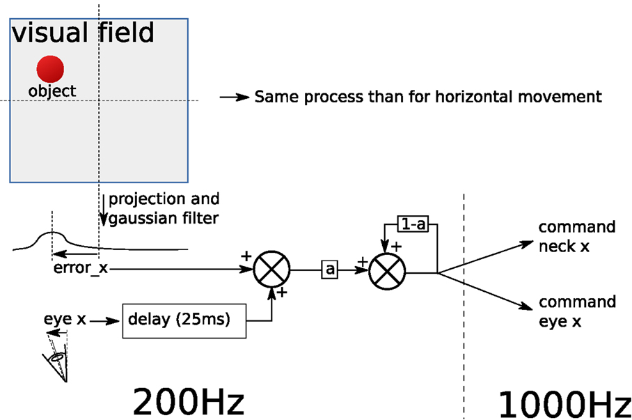
Figure 14. Architecture of the system processing the visual field and sending command to the eye and neck of the robot in order to keep the head facing a target (the ball) where eyex is the proprioceptive signal related to the eye current orientation and errorx is the distance of the target to the center of the camera field of view.
8.2.2. Tracking Results
A sinusoidal rotations of two sub-systems (eye and neck) of an amplitude equals to ±24° is shown in Figure 15A, while the robot tracks the ball oscillating at 0.5 Hz. Figure 15B presents the same results with oscillations at 1.5 Hz at a rotation angle of ±12.5°. From these graphs, a time delay between the eye and neck clearly appears (roughly equals to 0.1 s). Moreover, these experiments show that the design of the eyes allows fast ballistic movements of the cameras. Yet, because of the camera weight and the friction in the mechanical chain, very fast motions induce non-linear effects that cannot be easily corrected with a PID-like controller. This delay can be further improved in the future using an advanced adaptive algorithm for example. To conclude, although the experimental results show a slight difference in the amplitude and frequency, the head control well fits to provide the synchronization with the HYDROïD robot body motions. Tracking moving object results demonstrate the success of full integration of the proposed electric head prototype with the hydraulic arms of HYDROïD humanoid robot.
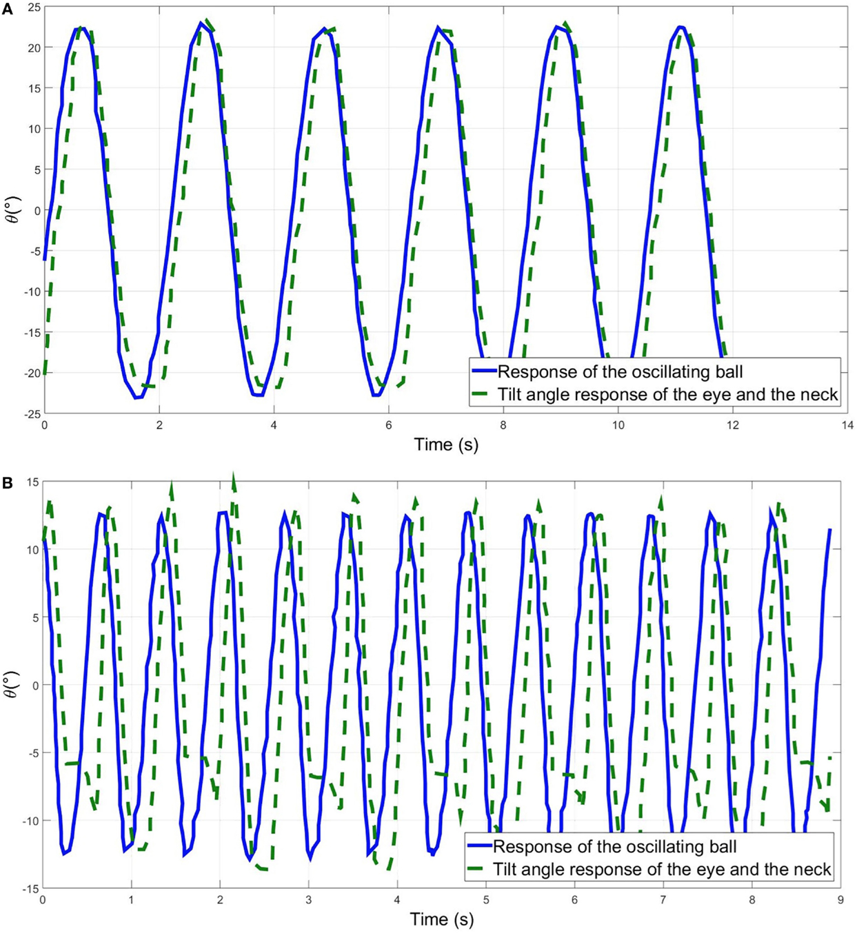
Figure 15. Yaw rotation of the eye and neck of the robotic head while tracking an oscillating ball at: (A) 0.5 Hz and (B) 1.5 Hz.
8.3. Demonstration of Basic Facial Expression Capabilities
In this experience, some basic facial expressions of the HYDROïD’s robot head are shown. To facilitate communication and interaction with human being, the basic facial expressions that the humanoid robot should exhibit are: happiness, sadness, anger, surprise, fear, and a neutral face (Nadel et al., 2006). The mouth, the eyes, and the eyebrows are the main sub-parts that govern these facial expressions. During happiness, the lips move down forming “V-shape,” with a neutral eyebrow and normally opened eyes. During sadness, the two lips are forming “inverted V-shape,” the eyebrows are slightly up. The right one rotates in a counter clock wise direction, while the left one is rotating in the opposite direction. In this case, the eyes are slightly opened. During anger, the lips are in the neutral contact position, the eyes are normally opened and the eyebrows are up. During surprise, the upper lip is up and the lower lip is down to form an “O shape.” The eyes are widely opened, while the eyebrows move slightly up. During fear, the lips have the same “O-shape” with slightly moving up of the lower lip. In this case, the eyebrows are moving up with the largest angle while the eyes are widely opened. Two basic facial expressions (happiness and sadness) are demonstrated by HYDROïD robot head using mouth and eyebrows mechanisms. The expression of emotions is linked to the presence of the colored ball in the field of vision of HYDROïD robot eyes. If the eyes are able to see the colored ball, HYDROïD robot is happy otherwise it is sad. The two facial expressions based on mouth and eyebrows mechanisms are shown in Figure 16.
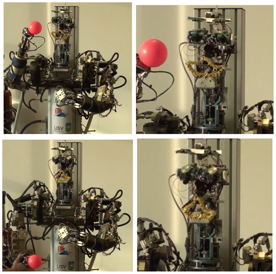
Figure 16. HYDROïD robot head showing basic emotions function of seeing the ball: happy (up left) with zooming on up right and angry (down left) with zooming on down right.
9. Conclusion and Future Work
In this paper, a new prototype for HYDROïD’s head was proposed. The designed and manufactured head is composed with four main sub-parts namely neck, mouth, eyes, and eyebrows. The adopted approach to carry out the design process was based on biomechanical study of geometrical and kinematic performances of the human head. The perception and expressive capabilities were also taken into account to fix the total number of 15 DOF for the proposed mechanism. A novel uncoupled eyes mechanism was chosen allowing HYDROïD’s head to be as far as we know, the first prototype able to simulate vergence as well as the concept of master-slave between eyes. A mathematical model for the neck and eyes movements was carried out in order to get the equation of motion and the transfer function for each joint movement. An identification of the natural frequencies was also carried out thanks to the developed models. The transfer functions were used for simulated position tracking by implementing a PID controller algorithm and determining the appropriate gain values. Then, the whole head mechanism was designed, manufactured, and assembled. The choice of electric actuation for the head was motivated by the required power for each joint. This choice makes HYDROïD a unique humanoid robot with hybrid actuation (electrical and hydraulic) depending on the power required for each DOF. Experimental results showing the perception and emotion capabilities were carried out with two versions of the head prototype, namely the head mechanism mounted on the upper body of HYDROïD humanoid robot and a standalone desk version. Motion ranges and kinematic performances were identified using the standalone version of the head prototype. A moving object (colored ball) tracking experiment as well as a demonstration of basic emotions was also carried out. From theses experiments, the synchronized motion between the electric head and the hydraulic arms validates the full integration of the proposed solution.
Future works will concern the enhancement of the perception and emotion capabilities of the proposed head. Indeed, an underdevelopment electronic nose will be added to the head in order to detect harmful and poisonous gases. Moreover, the further development on adaptive control algorithm as well as the hardware improvement should allow HYDROïD to be an advanced humanoid robot with perception and emotion capabilities.
Author Contributions
All authors contributed equally to this work. SA, ME, AA, and FO have conducted the state of the art, the mechanical design, the mathematical modeling, and the simulations. While AB, NB, and PG have prepared the computational architecture, the experimental design, performed the experiment, and analyzed the data. All authors discussed the results and implications and commented on the manuscript at all stages.
Nomenclature
| Tm | Motor Torque (N⋅m) |
| k1 | Yaw rotation stiffness (N⋅m) |
| k2 | Pitch rotation stiffness (N⋅m) |
| L1, L2 | Distance of different links (mm) |
| n1 | Reduction ratio in yaw rotation of the neck (–) |
| n2 | Reduction ratio in pitch rotation of the neck (–) |
| Pm, P1 | Motor power and transmitted power (W) |
| M1 | Mass carried by the yaw axis (kg) |
| μ | Belt transmission efficiency (–) |
| M2 | Mass carried by the pitch axis (kg) |
| ω1 | Rotational velocity of the yaw rotation of the neck (rad/s) |
| T1 | Torque in yaw direction (N⋅m) |
| ω0 | Rotational velocity of the motor rotating the neck in pitch direction (rad/s) |
| Ωp | Forced vibration of pitch rotation of the neck mechanism (rad/s) |
| Ωy | Forced vibration of yaw rotation of the neck mechanism (rad/s) |
| ωn | Natural frequency of the neck mechanism (rad/s) |
| ωnp | Natural frequency of pitch rotation of neck subsystem (rad/s) |
| ωny | Natural frequency of yaw rotation of neck subsystem (rad/s) |
| T2 | Torque in pitch direction (N⋅m) |
| Im | Motor moment of inertia (kg⋅m2) |
| I1 | Yaw moment of inertia (kg⋅m2) |
| I2 | Pitch moment of inertia (kg⋅m2) |
| θ1 | Yaw angle of rotation (rad) |
| θ2 | Pitch angle of rotation (rad) |
| α | Tilting angle of the head (rad) |
Conflict of Interest Statement
The authors declare that the research was conducted in the absence of any commercial or financial relationships that could be construed as a potential conflict of interest.
The reviewer GS and handling Editor declared their shared affiliation, and the handling Editor states that the process nevertheless met the standards of a fair and objective review.
Acknowledgments
The work was part of the INTERACT project funded by the ANR (French National Agency of Research) and partially supported by grants from the Labex Robotex.
Supplementary Material
The Supplementary Material for this article can be found online at http://journal.frontiersin.org/article/10.3389/frobt.2016.00015
References
Alfayad, S. (2009). Robot humanoide HYDROID: Actionnement, Structure Cinematique et Strategie de controle. Ph.D. dissertation, Université de Versailles Saint Quentin en Yvelines, Versailles.
Arent, K., Janiak, M., Kedzierski, J., Kreczmer, B., Malek, L., Muszynski, R., et al. (2008). Toward a Robotic Companion Design. Warszaw: Oficyna Wydawnicza Politechniki Warszawskiej.
Asfour, T., Welke, K., Azad, P., Ude, A., and Dillmann, R. (2008). “The Karlsruhe humanoid head,” in 8th IEEE-RAS International Conference on Humanoid Robots, Humanoids 2008 (Karlsruhe; Ljubljana), 447–453.
Banerjee, N., Long, X., Du, R., Polido, F., Feng, S., Atkeson, C. G., et al. (2015). “Human-supervised control of the ATLAS humanoid robot for traversing doors,” in IEEE-RAS International Conference on Humanoid Robots (Seoul: IEEE), 722–729.
Beira, R., Lopes, M., Praga, M., Santos-Victor, J., Bernardino, A., Metta, G., et al. (2006). “Design of the robot-cub (icub) head,” in Proceedings 2006 IEEE International Conference on Robotics and Automation, 2006 (ICRA 2006), Vol. 21, No. 10, pp. 1151-1175 (Japan: Advanced Robotics), 94–100.
Breazeal, C. (2003). Emotion and sociable humanoid robots. Int. J. Hum. Comput. Stud. 59, 119–155. doi: 10.1016/S1071-5819(03)00018-1
Delaunay, F., de Greeff, J., and Belpaeme, T. (2009). “Towards retro-projected robot faces: an alternative to mechatronic and android faces,” in IEEE International Symposium on Robot and Human Interactive Communication (RO-MAN) (Kobe: IEEE), 306–311.
Fitzpatrick, R. (2010). Designing and Constructing an Animatronic Head Capable of Human Motion Programmed Using Face-Tracking Software. Ph.D. thesis, Polytechnic Institute, Worcester.
Gouaillier, D., Hugel, V., Blazevic, P., Kilner, C., Monceaux, J., Lafourcade, P., et al. (2009). “Mechatronic design of NAO humanoid,” in IEEE International Conference on Robotics and Automation (Kobe: IEEE), 769–774.
Gross, H., Blechinger, F., Achtner, B., and Singer, W. (2008). Handbook of Optical Systems: Vol. 4 Survey of Optical Instruments, Weinheim: WILEY-VCH, 1092.
Ha, I., Tamura, Y., Asama, H., Han, J., and Hong, D. W. (2011). “Development of open humanoid platform DARwIn-OP,” in SICE Annual Conference 2011 (Tokyo: IEEE), 2178–2181.
Haley, J. (1988). Anthropometry and Mass Distribution for Human Analogues. Volume 1: Military Male Aviators. Ohio: Aerospace Medical Research Laboratory, Wright-Patterson Air Force Base, Report No. 88.
Hirai, K., Hirose, M., Haikawa, Y., and Takenaka, T. (1998). “The development of Honda humanoid robot,” in IEEE International Conference on Robotics and Automation, Vol. 2 (Leuven: IEEE), 1321–1326.
Hirth, J., Schmitz, N., and Berns, K. (2007). “Emotional architecture for the humanoid robot head ROMAN,” in Proceedings – IEEE International Conference on Robotics and Automation (Roma: IEEE), 2150–2155.
Jacob, R. J. K. (1993). Eye movement-based human-computer interaction techniques: toward non-command interfaces. Adv. Hum. Comput. Interact. 4, 151–190.
Kaneko, K., Kanehiro, F., Morisawa, M., Akachi, K., Miyamori, G., Hayashi, A., et al. (2011). “Humanoid robot hrp-4 – humanoid robotics platform with lightweight and slim body,” in Intelligent Robots and Systems (IROS), 2011 IEEE/RSJ International Conference on (San Francisco, CA: IEEE), 4400–4407.
Lapeyre, M., Rouanet, P., and Oudeyer, P.-Y. (2013). “The poppy humanoid robot: leg design for biped locomotion,” in Intelligent Robots and Systems (IROS), 2013 IEEE/RSJ International Conference on (Tokyo: IEEE), 349–356.
Lopes, M., Bernardino, A., Santos-Victor, J., Von Hofsten, C., and Rosander, K. (2009). “Biomimetic eye-neck coordination,” in IEEE – International Conference on Development and Learning (ICDL) (Shanghai).
Lutkebohle, I., Hegel, F., Schulz, S., Hackel, M., Wrede, B., Wachsmuth, S., et al. (2010). “The bielefeld anthropomorphic robot head,” in Robotics and Automation (ICRA), 2010 IEEE International Conference on (Alaska: IEEE), 3384–3391.
Meshram, P., and Kanojiya, R. (2012). “Tuning of pid controller using ziegler-nichols method for speed control of dc motor,” in Advances in Engineering, Science and Management (ICAESM), 2012 International Conference on (Nagapattinam, TN: IEEE), 117–122.
Nadel, J., Simon, M., Canet, P., Soussignan, R., Blancard, P., Canamero, L., et al. (2006). “Human response to an expressive robot,” in Proceedings of the Sixth International Workshop on Epigenetic Robotics. Lund University (Lund University Cognitive Studies; Vol. 128), 79–86.
Ogura, Y., Aikawa, H., Shimomura, K., Morishima, A., Lim, H.-O., and Takanishi, A. (2006). “Development of a new humanoid robot wabian-2,” in Robotics and Automation, 2006. ICRA 2006. Proceedings 2006 IEEE International Conference on (Orlando, FL: IEEE), 76–81.
Ouezdou, F., Alfayad, S., Pirim, P., and Barthelemy, S. (2006). “Humanoid head prototype with uncoupled eyes and vestibular sensors,” in Intelligent Robots and Systems, 2006 IEEE/RSJ International Conference on (Beijing: IEEE), 2980–2985.
Puig, J., Estrella, E., and Galán, A. (2002). Original paper ametropia and strabismus in Down syndrome SD-DS. Int. Med. J. Down Syndr. 6, 34–39.
Keywords: humanoid head, HYDROïD, perception, emotion, mathematical model, PID control, mechanical design
Citation: Alfayad S, El Asswad M, Abdellatif A, Ouezdou FB, Blanchard A, Beaussé N and Gaussier P (2016) HYDROïD Humanoid Robot Head with Perception and Emotion Capabilities: Modeling, Design, and Experimental Results. Front. Robot. AI 3:15. doi: 10.3389/frobt.2016.00015
Received: 20 November 2015; Accepted: 21 March 2016;
Published: 21 April 2016
Edited by:
Francesco Becchi, Telerobot Labs Srl., ItalyReviewed by:
Giovanni Stellin, Telerobot Labs Srl, ItalyJorge Velázquez, Engi-Com, Spain
Wiktor Sieklicki, Gdansk University of Technology, Poland
Copyright: © 2016 Alfayad, El Asswad, Abdellatif, Ouezdou, Blanchard, Beaussé and Gaussier. This is an open-access article distributed under the terms of the Creative Commons Attribution License (CC BY). The use, distribution or reproduction in other forums is permitted, provided the original author(s) or licensor are credited and that the original publication in this journal is cited, in accordance with accepted academic practice. No use, distribution or reproduction is permitted which does not comply with these terms.
*Correspondence: Samer Alfayad, c2FtZXIuYWxmYXlhZEBsaXN2LnV2c3EuZnI=