Abstract
In robot-assisted teleoperated laparoscopic surgeries, the patient side manipulators are controlled via the master manipulators, operated by the surgeon. The current generation of robots approved for laparoscopic surgery lack haptic feedback. In theory, haptic feedback could enhance the surgical procedures by providing a palpable sense of the environment as a function of surgeon’s hands movements. This research presents an overall control framework for haptic feedback on existing robot platforms and demonstrates on the daVinci Research Kit. Toward this end, the paper discusses the implementation of a flexible framework that incorporates stiffness control with gravity compensation for the surgeon manipulator(s). This is coupled with a sensing and collision detection algorithm for calculating the interaction between the slave manipulators and the surgical area.
1 Introduction
Robotic surgery has seen significant advancement since its inception in 1980s, when PUMA 560 was used for a neurosurgical biopsy (Kwoh et al., 1988). The idea of robots in surgery was aimed more toward proof of concept rather than immediate advantages over traditional surgery. Multiple robot-assisted surgeries and developments followed in the next few decades, some of them being the development of a teleoperated surgical robot by Taylor et al. (1995), a cholecystectomy (Gagner et al., 1994), prostatectomy (Davies et al., 1989), hip-replacement (Bann et al., 2003), and lower abdominal laparoscopy (Satava, 2003).
By the turn of the century, many of these technologies/robots were either deprecated or merged into the daVinci Surgical Robot (Marohn and Hanly, 2004). By this point in time, robot-assisted laparoscopy had already showed its potential over traditional laparoscopy (Patel et al., 2007). Some of the advantages of robot-assisted surgery addressed the elimination of fatigue for labor-intensive movements, natural as opposed to laparoscopic motions of instruments, increased precision, ease of use, and motion scaling. At the same time, robot-assisted surgery had drawbacks over traditional surgery. These disadvantages included loss of touch/haptics, non-stereoscopic view of the internal body/organs, and reduced degrees of freedom among others.
In 2001, Intuitive Surgical was awarded the FDA approval for lower abdominal laparoscopic surgeries to be performed by the daVinci Surgical Robot (Talamini et al., 2003). The daVinci has since performed millions of surgeries (The Economists Online, 2012) and continues to dominate the medical space for robotic surgery. The company has introduced several generations of the daVinci. The daVinci robot has overcome some of the disadvantages of early robotic laparoscopies by providing the same operating degrees of freedom as possible with open surgery, stereoscopic view of the internal body by using maneuverable stereoscopic endoscopes, and comfortable control of the slave arms, using foot pedals. The slave arms of the daVinci are also mechanically compliant by having a fixed remote center for insertion into the body.
Recently, the fields of computer vision, perception, motion planning, and actuation, which are essential components of robotics, have been making strides in terms of research and application. Partly, this has been possible due to the increased collaboration between different researchers and, thus, producing new software and hardware tools. As a positive consequence, the release cycle of updates to these tools has become consistent as increasing number of researchers have come on board to the open source community. Many of these tools are now used as a standard.
This research focuses on the development of new tools and also tailoring several general purpose robotic tools for application in medical robotics. More specifically, this research provides a study and implementation of a haptic feedback framework for teleoperated, minimally invasive surgery. The study intends to take a step toward intelligent, generic, and customizable solutions to address some of the short comings associated with robot-assisted surgery and haptics (Bennett et al., 1997).
1.1 The daVinci Research Kit
The daVinci Research Kit (dVRK) is a shared development platform. The intent behind such a platform is to enhance collaborative research and development of new technologies for robot-assisted, minimally invasive surgery. The dVRK includes the clinical daVinci Surgical platform without the proprietary controllers and software. The platform includes a surgeon console, patient side manipulators (PSMs), endoscopic camera manipulator (ECM), and a foot-pedal tray. The surgeon console houses two master tool manipulators (MTMs) and a stereoscopic viewing system. The kinematic structure of the PSMs and the ECM is similar. The surgeon controls the PSMs using MTMs by engaging/disengaging foot pedals. The dVRK setup at AIM Labs is shown in Figure 1.
Figure 1
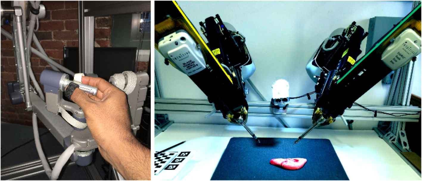
MTM on the left and the two PSMs on the right. dVRK setup at AIM Lab, WPI.
The task of setting up the controllers and initial software for the dVRK was carried out at John Hopkins University (JHU) (Deguet et al., 2008; Jung et al., 2009). AIM Lab at Worcester Polytechnic Institute has been actively involved in the successive development and distribution of the hardware controllers to all the universities, part the dVRK program (Kazanzidesf et al., 2014). Both the hardware controllers and the software (CISST/SAW Libraries) are open source. A significant amount of work has been done to include general purpose and modern robotics tools to the dVRK, predominantly focusing on building a ROS interface.
The development of a ROS interface has allowed for the inclusion of several generic robotic tools to the dVRK. An example is the inclusion of a motion planning framework for the dVRK (Zhang et al., 2014). The motion planning framework allows for detection and intelligent manipulation of the PSMs in simulated and real environments, though the research is far from actual surgical applications.
Both MTMs have 7 active joints and are similar in terms of kinematics. The first three joints allow for movement in Cartesian space, while the last four joints have intersecting axes, forming a gimbal mechanism, with one degree of redundancy. The last link has a gripper pinch, which is ignored for the purpose of kinematic and dynamic evaluation. The PSMs have 6 DOF each, with gripper fingers at the end, which are directly controlled by the gripper pinch of the MTMs. Like the MTMs, the gripper opening angle is ignored for kinematic analysis.
2 Setting up a Haptic Feedback Framework
2.1 Related Work in the Field of Haptic Rendering
Haptic rendering in virtual environments has been a considerably investigated field. Baraff (1994) proposed a haptic rendering interface for non-penetrating bodies with focus on high speed performance. Srinivasan et al. (1996) presented a study of the effect of visual cues incorporated with kinesthetic devices. This study showed the dominance of perception feedback of the visual cues over the haptic feedback calculated from the actual topography of the object. Feedback forces evaluated from point contact with volume visualization was explored by Avila and Sobierajski (1996) and showed promising results. A numerical approach to haptic processing algorithms was presented by Ellis et al. (1996). This research also presented the implicit effects of dealing with computation and transmission of haptic forces using discrete systems to end-user.
Haptics involving textural information was introduced using ray-based mapping by Basdogan et al. (1997). This technique, similar to the previous ones, exploits the learning from computer graphics for use in haptic rendering. Bump mapping was used to generate a textured surface with coulomb friction along the tangential direction. Green and Salisbury (1997) also proposed texture-based haptics with the sensing of virtual soil texture. Latimer (1997) presented an in-depth review of interaction between different polygonal rigid bodies and their haptic interaction thereof. His work also focused on the challenges of directional impact of rigid bodies and their effect on the feedback force. The role and application of haptics in shared platforms has been investigated by Buttolo et al. (1997). Multiple users connected via a network were tested against the effects of latency of haptic information. Research toward the haptics for soft tissues, mimicking body tissues, has been growing lately. Costa and Balaniuk (2001) presented the application of long elements method for the estimation of object deformation. This deformation was then utilized for haptic rendering.
The work of Okamura (2004), Ryden et al. (2011), and Westebring-Van Der Putten et al. (2008) is also notable. Ryden presented a novel proxy-based approach toward haptic feedback, where a deflection from a proxy region is used to compute haptic feedback. Okamura presented the study of various haptic devices, different types of interaction control, and their effect on the use of these devices. Wurdemann et al. (2013) presented a novel sleeve wearable that interacts with the operators forearm to provide haptic sensing. A pseudo haptic feedback (PHF) methodology was presented by Li et al. (2015) using visual cues for deformation information to the operator rather than force feedback. Such an approach does not require hardware for implementing force feedback.
As discussed in Section 1, one drawback associated with laparoscopic surgery is the loss of haptics and, while there has not been a conclusive study to prove its effectiveness, it is generally believed that its inclusion should enhance the surgical procedures. Luk et al. (2006) and Bethea et al. (2004) discuss surgical experiments performed with and without haptic feedback and present some interesting results. The results suggest that the accuracy and duration of the surgical procedures did not improve noticeably using haptic feedback. At the same time, Santos-Carreras et al. (2010) argues that the operative performance is improved significantly using haptic feedback. However, needless of the debate of whether haptic feedback is as effective as it is perceived to be, many researchers have focused toward the study and development of haptic interfaces for surgical manipulators.
The current research in haptics particularly uses impedance/stiffness control for feedback. Toward this end, the goal is to develop algorithms and techniques for generation of position/velocity deflections from interactions with the environment. These deflections are then used as inputs for haptics feedback using impedance control or stiffness control. For force feedback, commercially available devices (e.g., Phantom and Novint) are used. These devices have links with low inertial properties, thus, aiding in an accurate implementation of impedance control and are mostly used in training simulators rather than actual surgery.
Hagn et al. (2008) have developed a light weight arm (having low inertial masses) for surgical applications. The design choices involving low inertial properties of this robot allow for easier implementation of force control for surgical applications. For teleoperated surgical robots, such as the daVinci, the master manipulator consists of links that have relatively larger inertial parameters compared to commercially available haptic devices. On top of that, most of these inertial parameters are not precisely known. This makes the interaction using impedance control very challenging.
A framework capable of sensing the environment, analyzing the interaction with the environment, and computing haptic feedback requires a few additional components, which are not part of dVRK. First, to scan the operating environment of the PSMs, different types of imaging/scanning sensors are required. Second, the registration of PSMs to each other and the operating environment is required. This entire framework is shown in Figure 2. The framework as shown is under development. Currently, only one pair of PSM and MTM is used for haptic feedback. Meshes replicating the operating environment are manually registered to the PSMs.
Figure 2
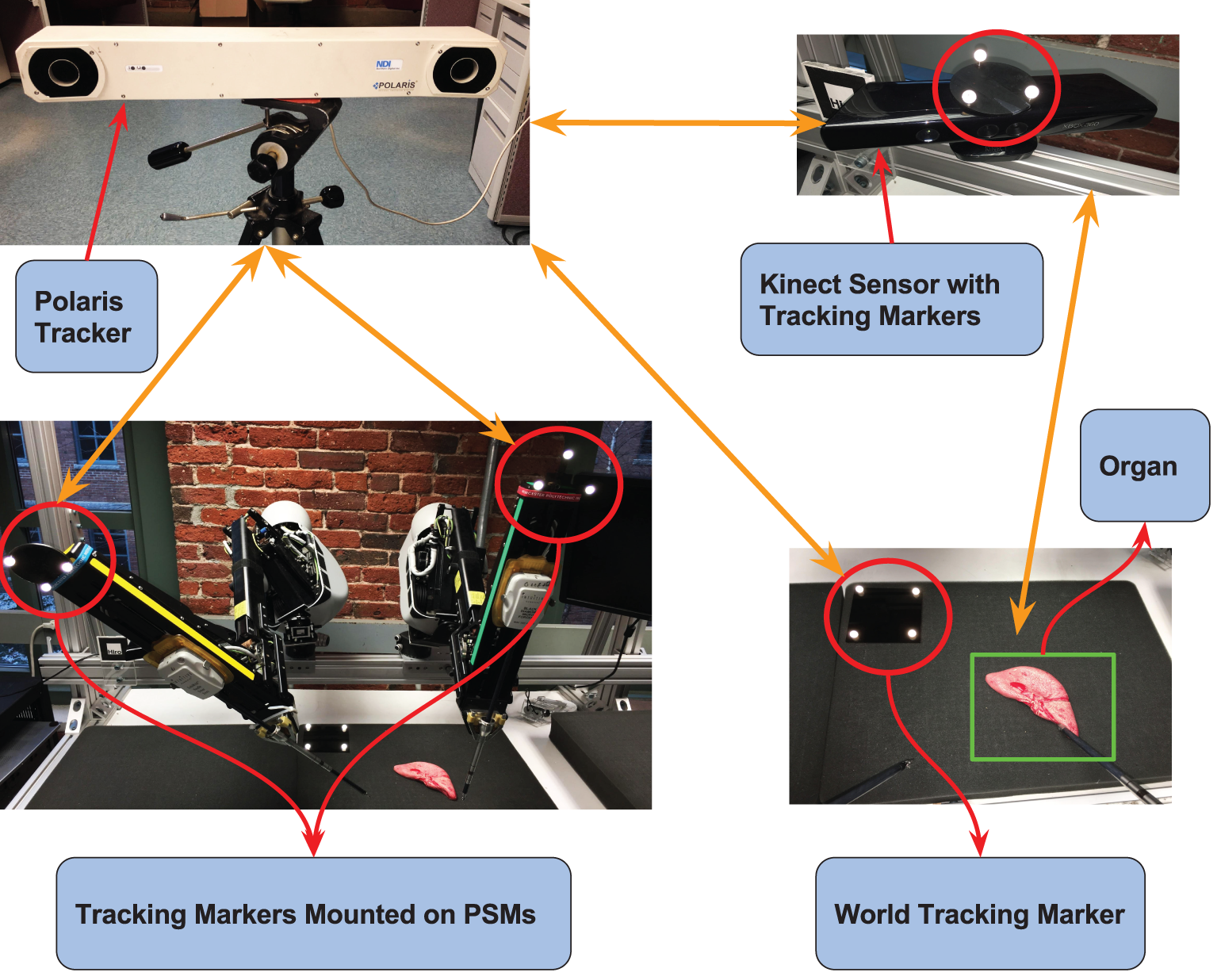
An overview of the components and their interface with each other to enable haptic feedback. The Polaris Optical Tracker tracks the tracking markers mounted on the PSMs, the Kinect Sensor, and the World Frame. The Kinect Sensor tracks the organ/surgical environment.
2.2 Interaction Control of the MTM
As discussed in Section 2, the implementation of impedance control on the Master of dVRK is a challenging task. The main reason is the large inertial parameters of the MTM combined with inaccurate models for the actual inertial values. This section deals with the development of a stiffness control strategy for the MTM of the dVRK; however, the techniques used are generic so that any master manipulator of a surgical robot can be used for haptic interaction.
2.3 The General Dynamics of the MTM
Hogan (1984) proposed the use of impedance control for haptic interaction, while Newman (1992) provided the use case of an admittance controller for natural interaction. These researchers formed the basis of two different school of thoughts for interaction control. In impedance control, an input deflection in position results in the computed force as output, while in admittance control, an input force results in a deflection of position as the output. For admittance controllers, force sensors at the tips are required to sense the interaction forces from the environment. It is not feasible to mount force sensors on the robot tips for applications, such as laparoscopic surgery.
Admittance control is possible without active force sensing, but tends to be inaccurate. Without active force sensing, the admittance control is usually aimed for very slow and steady motions of the manipulator. The goal is to minimize the accelerations and velocities that drive the inertial and Coriolis dynamic components. Due to these restrictions, a specialized impedance control is chosen for the MTMs with just the proportional and damping gains. This control scheme is classified as stiffness control (Siciliano and Villani, 2012). Consider the general dynamic equation of a manipulator.
where M(q) ∈ ℝn×n is the Inertia matrix, is the Coriolis matrix, G(q) ∈ ℝn×1 Gravitational vector, and τ ∈ ℝn×1 and τe ∈ ℝn×1 the dynamic and external torques on the manipulator. Equation 1 provides the dynamic behavior of the system in joint space. A more useful approach is to transform the joints space dynamics into Cartesian space. Using the Jacobian J(q) ∈ ℝn×p and some pre and post multiplication of the terms of M(q), , and G(q), we arrive at the following equation that represents the system dynamics in Cartesian space.
In equation 2, a and v represent the instantaneous Cartesian acceleration and velocity vectors of the end-effector. F and Fe are the dynamic and external wrenches on the manipulator. The remaining terms are evaluated as follows:
The conversion from joint space to Cartesian Space requires cross multiplication of the inverse of the Jacobian J(q) with the inertia, Coriolis, and gravitation terms. Since there is no guarantee of the inverse of the Jacobian to exist, pseudo inverses are required, which tend to make the Cartesian dynamics inaccurate. Each MTMs is a 7-DOF manipulator, which requires the pseudo inverse of the Jacobian to be computed at all times. One way to avoid taking the pseudo inverse is to distribute the kinematics of the MTM and consider only the first three links. This allows for just the external forces Fe = [FxeFyeFze]′ to be included in the dynamic model while ignoring the end-effector torques Te = [TxeTyeTze]′. As a direct consequence, this takes away the capability to generate wrist moments ηe = [ηxeηyeηze]′ for haptic sensing. Although not ideal, this is certainly acceptable as proposed by Santos-Carreras et al. (2010). This research demonstrated that the change in performance of surgical tasks remained insignificant with the addition of wrist moments.
2.4 Stiffness Control using Dynamic Haptic Model with Gravity Compensation
The haptic feedback force is treated as the end-effector wrench, transmitted to the user holding the MTM. This wrench is computed from the interaction of the PSM with the environment. The interaction of the PSM with the environment results in a deflection ∂(x) that represents the penetration depth. Assuming a contact with a rigid environment, the interaction is modeled using a 3-DOF elastic spring and damper. The rigidity of the environment is controlled by the gains for elasticity and damping. The elastic gain K and the damping gain B are essentially multi-dimensional mapping functions, providing stiffness and damping in Cartesian space.
In equation 6, a spatial force at the PSM is expressed in MTM’s Body Frame. is the constant transformation between the PSMs and MTMs Base frame, and is the transformation between MTMs Base and Tip frame. The transformation is the function of q = (q1, q2, … , q7)T, the MTM joint angles.
In equation 6, K and B ∈ ℝ3×3 and are diagonal matrices:
Introducing Fhaptic in equation 2 to combine the haptic feedback force with the dynamics of the MTM, the complete dynamics of the MTM for haptic interaction is derived.
As discussed in Section 2.2., the inertial parameters of the MTM are not accurately known. Inaccuracies in these parameters make a stable impedance control challenging, if not unachievable. Keeping in mind the challenges involved with impedance control, a stiffness controller with gravity compensation is chosen. Since the gravitational vector is a function of joint positions, it can be estimated using regression of known parameters and estimated parameters. A model of the gravitational vector is developed using the potential energy functions of the links P(q):
In equation 11, is the regressor matrix, while in equation 12, ΠE is a vector of estimated parameters using the manual calibration of torques at different configurations to keep the arm stationary with minimum input.
For special scenarios in which the environment is static, the desired velocity in equation 6 is set to 0 so that the goal of B is to minimize the residual velocity once a contact between the PSM and the environment happens. Additionally, for cases involving the motion of the MTM with minute end-effector acceleration and velocities and considering equation 11, equation 9 leads to equation 13.
The high level haptic force control loop is set to run at 500 Hz, with a consistent update rate to the MTM controllers. The haptic force control loop runs as ROS application compiled using C++. The low level torque controller (CISST/SAW) runs at a much higher speed and maintains the torque in between the update cycles of haptic feedback. Higher speeds are possible but have not been tested. A block diagram for the control scheme is shown in Figure 3.
Figure 3
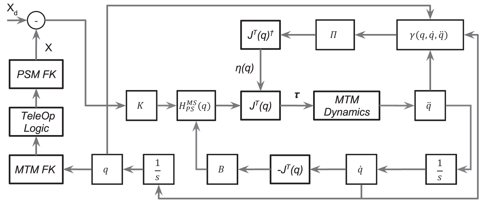
A block diagram of the controller used for Haptic Feedback at MTM. The figure shows the use of the deflection ∂(x) = xd – x of the PSM used to generate the haptic feedback. The block-labeled MTM Dynamics represents the actual MTM with implicit dynamics.
3 Sensing and Manipulation of Simulated Environment
The actual surgical environment has to be sensed and then visualized before any haptic feedback can be computed. The setup to achieve this sensing is shown in Figure 2. As mentioned before, this setup is currently under development. Once this setup is complete, the sensed environment can be visualized in simulation on which manipulation tasks can be performed.
The visualization of the environment can be replaced by virtual environments until the setup in Figure 2 is complete. For performing manipulation tasks on the virtual environment, a motion planning framework has been developed for the dVRK. This motion planning framework is developed using several native ROS tools. This framework involves ROS as a high level control architecture communicating with CISST/SAW libraries (lower level control architecture). This hierarchical control scheme allows for performing algorithmic tasks using self created or existing ROS tools while at the same time, maintaining low latency and high bandwidth control of the actual manipulators.
The motion planning interface for the dVRK relies on MoveIt (Chitta et al., 2012) and Fast Collision Library (FCL) (Pan et al., 2012). Using the current motion planning framework, a mesh object is loaded in simulation as a planning scene and fast collision checking is performed with the PSM. The collision checking is used to retrieve one or more collision points per collision pair. The collision pair is a link from the robot and the environment mesh. Figure 5B shows a 3D volumetric skeletal model, a PSM, and also the collision points from the collision between the two. To allow for the teleoperation of the simulated PSMs using actual MTMs, the interface shown in Figure 4 has been developed.
Figure 4
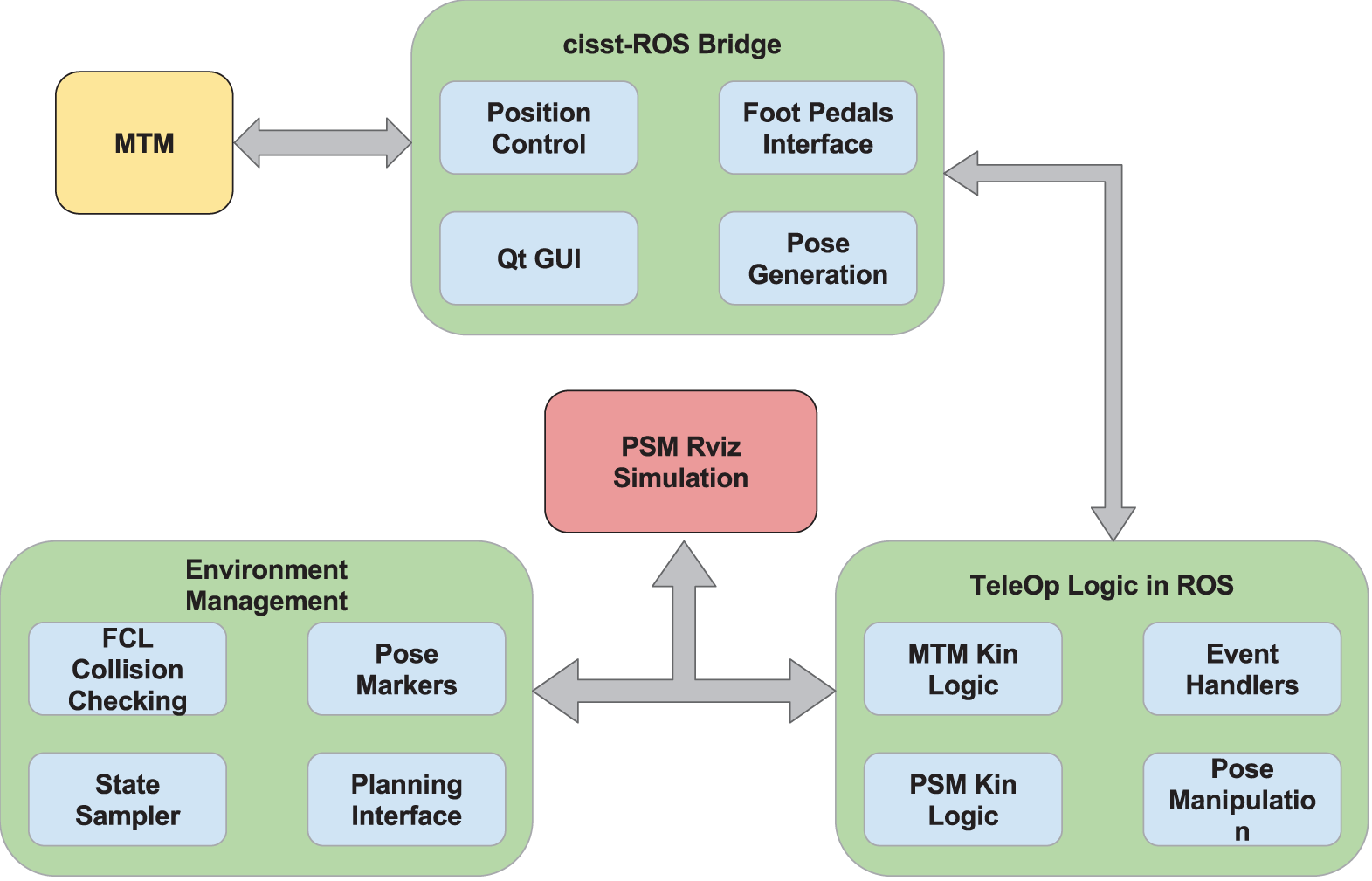
Packages involved in teleoperation of simulated PSM using actual MTM.
Figure 5
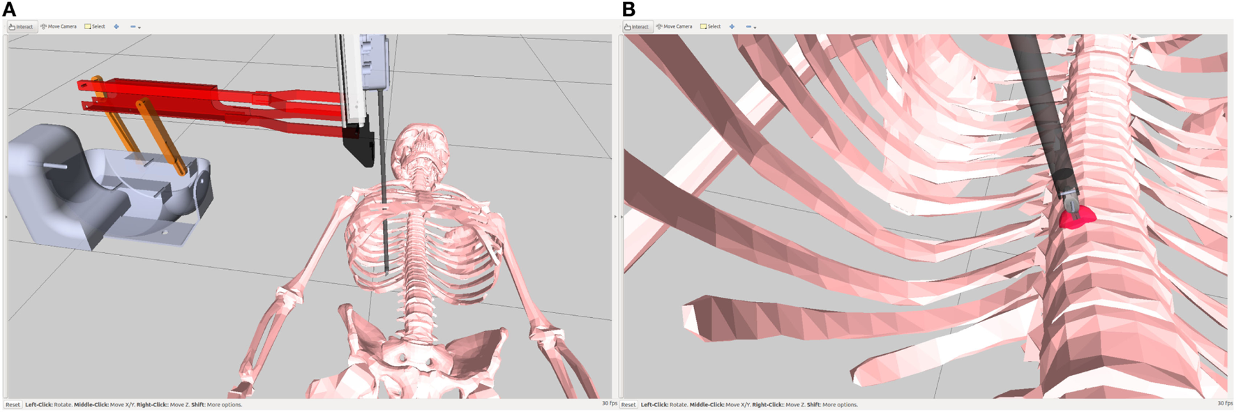
(A) shows the simulated PSMs and a volumetric skeletal mesh in front of it. (B) shows the collision of the PSM with the volumetric skeletal mesh.
3.1 Collision Checking
The simulated PSMs are controlled via teleoperation of the actual MTMs using the interface shown in Figure 4. Once the simulated PSMs come in contact with the collision environment, a deflection needs to be computed that is then fed as an input to equation 13. The outcome of this equation is the haptic force exerted by the MTM. With the control architecture, the surgeon/user grasping the MTM gets a sense of the environment being manipulated based on this interaction of the PSM with the environment.
Computing the interaction deflection using the collision checking capabilities of FCL has a few short comings. First, FCL only provides the points where the collision occurs and not the explicit information of the surface normal at that point. Normals can be extracted from FCL by some changes to the API but the normals at point contact are not the surface normals. Instead, these normals are “adjusted normals,” which are computed using summation of all the normals from the multiple contact points. Thus, the “adjusted normals” are useless for computing the correct deflection. A mesh environment is loaded for collision checking as demonstrate in Figures 5A,B. The resulting collision point is shown in red.
One solution is to explicitly compute the normals of the entire mesh environment on which the collision checking must be performed. As a result, we can read the normal vector(s) corresponding to the collision point(s) and generate directional forces in that direction. This approach requires pre-computation and storage of normals for the collision mesh, which is both computationally demanding and requires modifications to the established framework for dVRK and MoveIt.
Another possible approach to address the problem is to use the direction of velocity of the PSMs end-effector, v, just before the collision occurs. Using only the direction of velocity, it can be shown that such an approach only works for cases in which the direction of approach of the PSM is normal to the surface. For different angles of approach, the direction of feedback force is not normal to the collision surface. The problem in this case is addressed using concepts from geometry, which are presented as follows.
3.2 Point Contact between Two Surfaces
For a continuously differentiable, parametric surface represented by U, the surface gradient of U can be used to calculate the surface normal to any given point.
where ϵx1 = [1 0 0], ϵx2 = [0 1 0] and ϵx3 = [0 0 1]. Given a point of interest with the corresponding normal :
Now a second non-intersecting surface V, with normal ψ(y1, y2, y3) is represented as:
As shown in Figure 6A, when the two surfaces U and V approach a point contact such that Δ(U, V) approaches zero; at point contact, the two surface normals and become collinear. This property of point contact is exploited to create a spherical proxy region (SPR) at the tip of the PSM, where the interaction with the environment takes place Figure 6B. The SPR is modeled with 3-dimensional spring and damping components, which is shown elaborately in Figure 7. Figure 8 shows the SPR modeled around the tip of the PSM. As the PSMs tip and correspondingly the SPR is pressed into the collision mesh, the deflection is visualized by the red arrow.
Figure 6
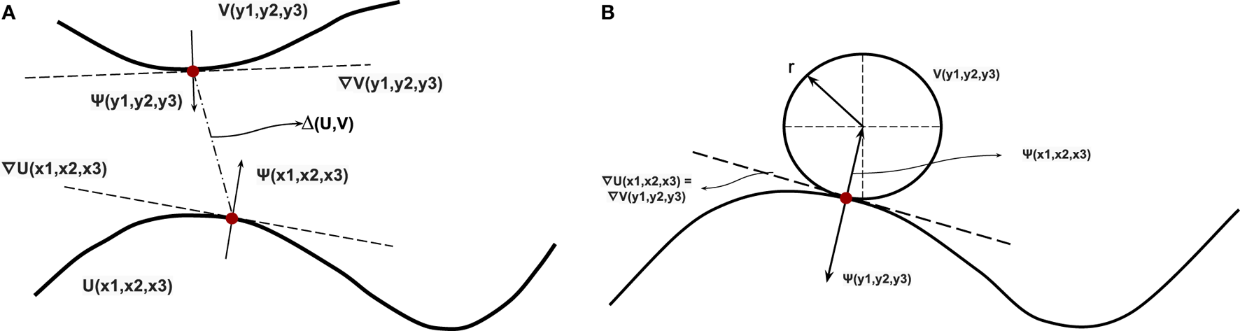
(A) Two parametric surfaces represented by U(x1, x2, x3) and V(y1, y2, y3) and their surface gradients shown as ∇U(x1, x2, x3) and ∇V(y1, y2, y3), respectively, (B) Point contact between a parametric surface U(x1, x2, x3) and a sphere V(y1, y2, y3). At point contact, their surface gradients ∇U(x1, x2, x3) and ∇V(y1, y2, y3) are equal to each other.
Figure 7
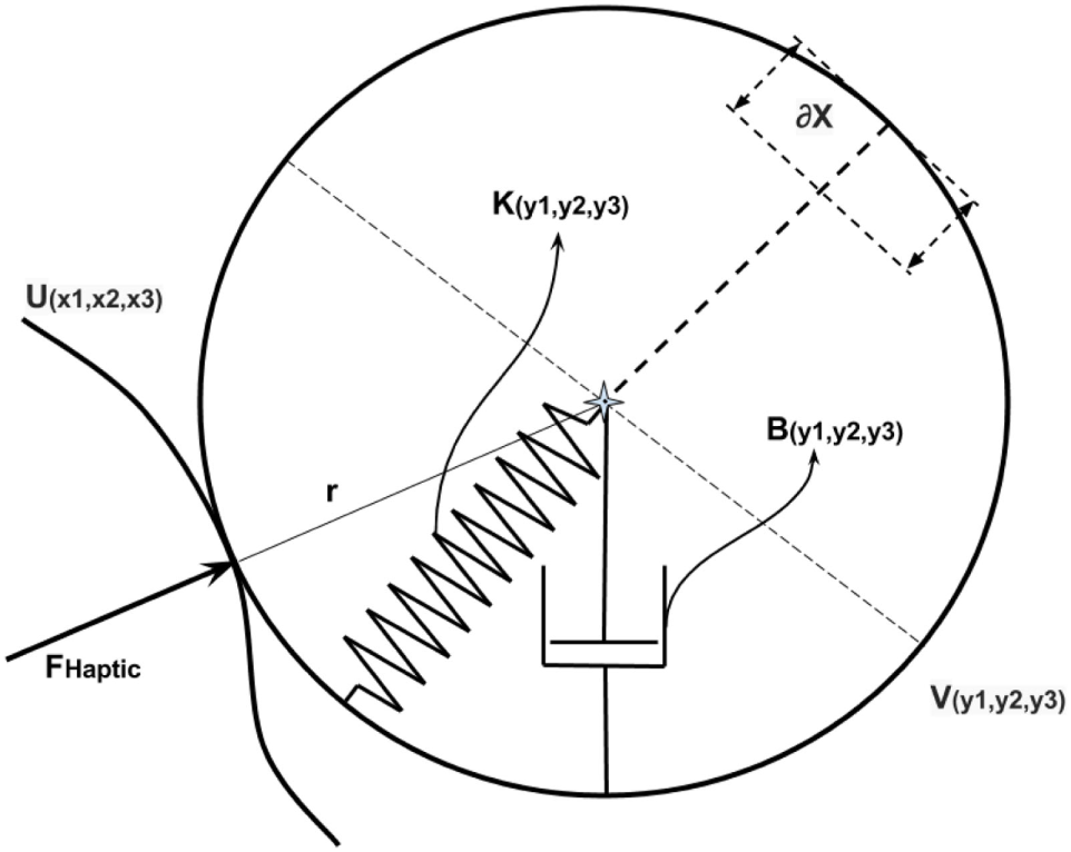
Spherical proxy region modeled as a 3-dimensional spring and damper.
Figure 8

The elasticity of the SPR while interacting with environment. The deeper the SPR is pressed, the greater is the normal force vector.
3.3 Spherical Proxy Region Sliding Along the Environment Mesh
The contact of the SPR with a collision environment is used to get the initial direction of the haptic force. As the SPR penetrates inside the collision environment, the FCL collision checker reports the collision points along the surface of the two meshes. This implementation is replicated for a 2-dimensional case shown in Figures 9A,B.
Figure 9
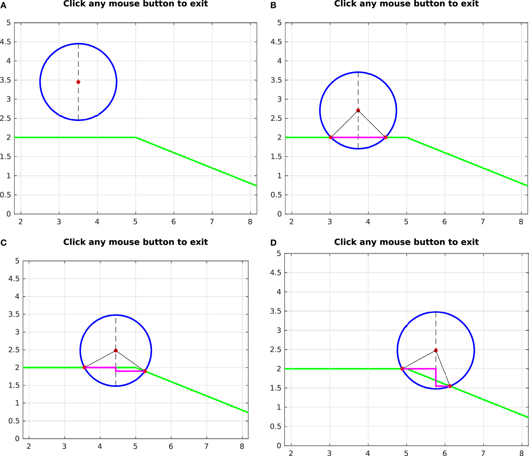
The insertion of the SPR into mesh environment causes the contact points to slide along the mesh face based on ∂x, shown in (A,B). In (C,D), as the SPR slides between two mesh faces along the direction of the previous mesh face, the new mesh face causes the contact point to change based on ϕf.
The effect of getting collision points only on the surface means that, once the SPR penetrates a collision object, the calculation of the normals using the difference between the SPRs center and the contact point is no longer valid. Similarly, sliding the PSM along the surface of the environment result in the projection of δx on the normal n at an angle to the actual normal of the environment. This can be seen in Figures 9C,D. The environment is modeled using mesh that constitutes many faces. The angle between two neighboring mesh faces is represented by ϕf. As the SPR keeps moving in the direction of the previous face, the point contact keeps moving along the circumference of the SPR and the plane of the mesh face, until the next mesh face approaches. Depending upon the angle ϕf of the next mesh face with respect to the previous one (shown in Figure 10), the contact point moves about the SPR circumference. This movement of the contact point is related to ϕf.
Figure 10
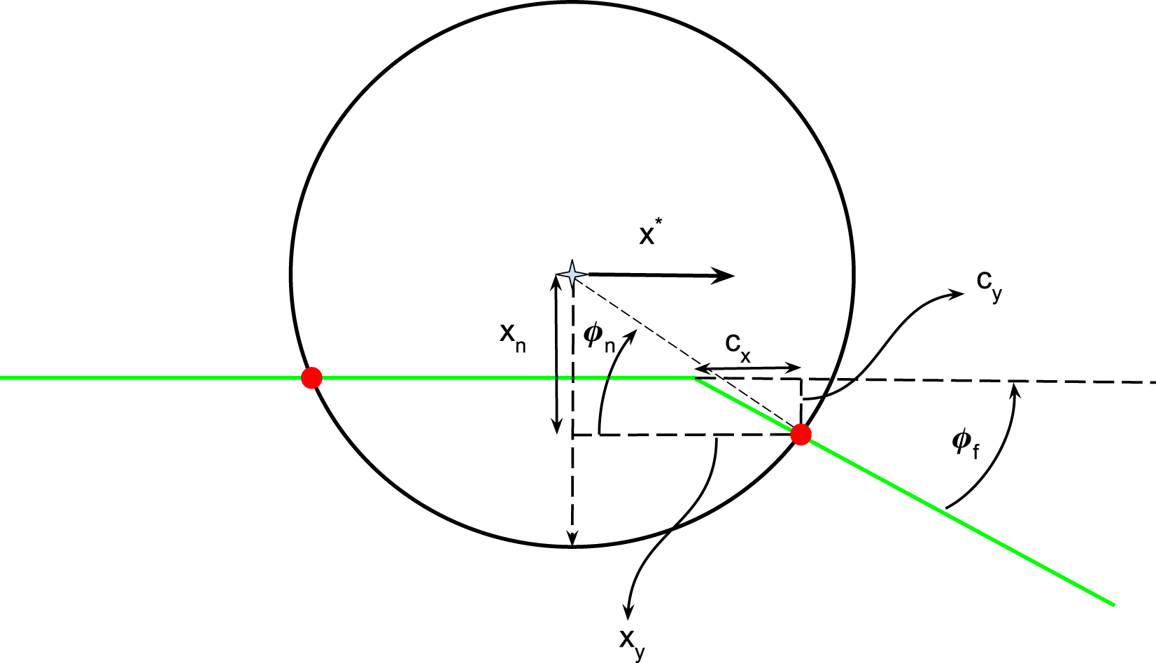
SPR labeled with variables (cx, cy, ϕn) that change with the slide along the mesh surface.
The relation between the movement of the contact point along the surface of the environment mesh and the change in ϕn is not linear. The goal is to determine the angle ϕf. It can be seen in Figure 11 that, as the face angle ϕf varies for different faces, cy behaves like a different sinusoid. Specifically for the face angle of ϕf = 90, the sinusoid can be expressed as cy = sin(ϕn) and δcx = 0. For other angles of ϕf, the sinusoid at ϕf = 90 is projected onto the line/plane angled at ϕf.
Figure 11
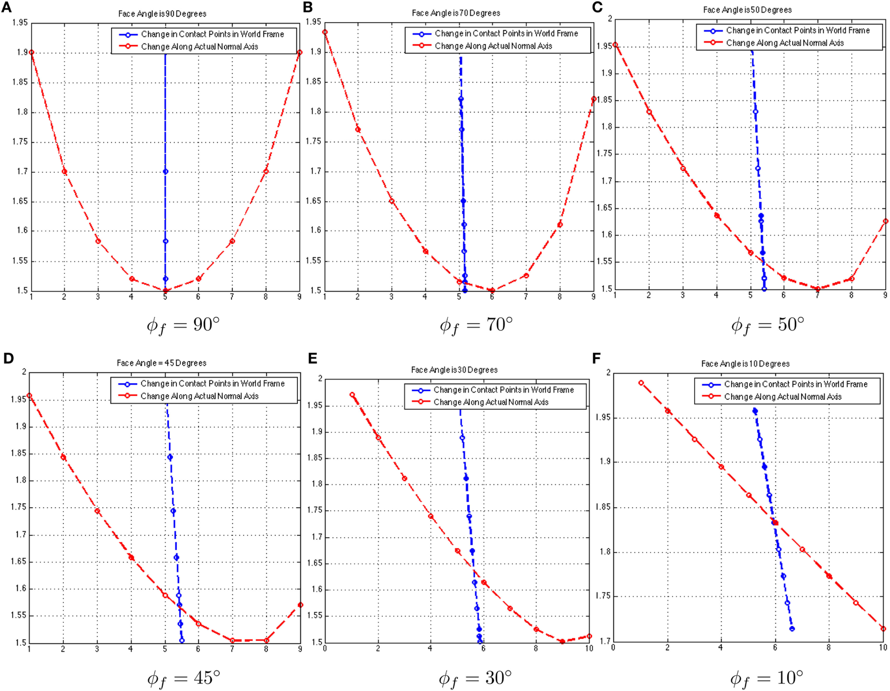
From (A–F), the curves in red shown cy = cx tan(ϕf) and the lines in blue show (δcy, δcx).
One other factor affecting the sinusoids formed by the slide of SPR is the penetration depth. Thus, ϕy is a function of the variables cy, cx, and xn, which makes it harder to solve for. This is true since separate loops are required to determine these variables. cy and cx are harder to maintain as they are measured only when the contact point starts to move along the new face.
Instead of keeping track of cy, cx, and xn, an elegant approach is presented to directly compute ϕf at all times after the initial contact. Since the velocity of the contact point c is always along the surface of the environment mesh:
And a normal of the new face can be computed directly as:
For a 2D case, this would return two different directions of nf ; hence, assuming that the collision mesh is locally convex, the correct nf is the one that satisfies the property:
For a 3-dimensional mesh, instead of getting vf, a plane is grown with at least three update contact points as the SPR moves along the mesh. The generation of this plane allows for the computation of the normal to the mesh face. The advantage of this technique is that it does not depend explicitly on the motion of the SPR; hence, there is no need to maintain the information of the parameters xn, yn, and ϕn, as these could be prone to errors based on the shift of cy along xy.
4 Results
Figure 12 shows the results of haptic feedback on a few different meshes. In the sub-figures shown, as the SPR slides into the mesh, a deflection is shown emanating from the SPR. This deflection is then used to get a haptic feedback force on the MTM based on Algorithm 1. In Figure 12, the resultant force in the body frame is shown in red, while the one in spatial frame is shown in green.
Figure 12

(A,C,E,G) show the PSMs interaction with different mesh environments. (B,D,F,H) show the corresponding haptic feedback at MTMs for each case respectively. The diameter of the SPR is 30 mm.
Algorithm 1
| 1: while collision = true do |
| 2: Retrieve Collision Points pi where i ∈ 1, 2, … , z |
| 3: Get Collision Normals ni |
| 4: |
| 5: Calculate δxtotal |
| 6: Retrieve |
| 7: Compute |
| 8: Compute |
| 9: Compute |
| 10: end while |
Generation of haptic feedback.
The choice of the diameter of the SPR does not directly affect the computation of the haptic force, what it does affect is the collision detection and generation of deflection forces for the environment mesh. A greater radius of the SPR will smooth the directional changes of the normal when the SPR slides along the mesh face; however, it would tend to be inaccurate for smaller topological details of the mesh. A smaller radius is sensitive to changes in the topology of the mesh but results in a noisy deflection force. The next step is to study the relation of the radius of the SPR and the accuracy vs. stability of the computed deflection. In a more general sense, the radius of the SPR in greatly affected by the procedure and the environment at hand. An environment with finer details would require a smaller radius of the SPR, which would avoid smoothing out the smaller details and enable accurate sensing. Similarly, a noisy environment would require a greater radius of the SPR in addition to a filtering algorithm to avoid the noise being treated as sharp edges.
The current procedure requires a relatively dense mesh with a larger number of faces compared to the local curvature at any given point. Such a condition is required to keep the deflection of the SPR and the computed haptics forces smooth in terms of their direction. As the SPR traverses along the mesh, the angle for incoming faces ϕf varies, if ϕf is relatively large between two faces, the computed normal will shift by the same angle causing discontinuities in the direction of the haptic force. One solution is to introduce a filter on the update of haptic forces such that the rate of change of the haptic force can be minimized within reasonable bounds.
For the current implementation, the values of Kp and Kd have not been calculated scientifically. Since the interaction of the SPR with the collision mesh is non-passive, the interaction introduces energy into the system. This energy causes oscillations; to keep the system stable, this energy needs to be dissipated. There are two types of damping that control the energy flow at interaction, the damping gain Kd and the natural damping of the users hand. The effect of damping caused by the user hand plays an important role in the stability of the system. Colgate and Brown (1994) talk about adjusting the damping and sampling rates to improve the bounds of interaction control for a single DOF joint. For implementing a similar strategy on the multi-DOF arm such as the MTM, more work needs to be done. For test cases, a virtual wall is created in the x, z plane located at y = 0.385 relative to the MTMs base frame. The purpose of the wall is to apply haptic feedback on the MTM, if it tries to penetrate through. Figure 13 shows the change in MTM position along the y axis, as it approaches the wall. As shown in the Figures 13A–C, a higher damping gain reduces the offshoot of the MTM position but does so at the cost of rigidity of the wall. The numerical values for the controller performance shown in Figure 13 are expressed in Table 1.
Figure 13
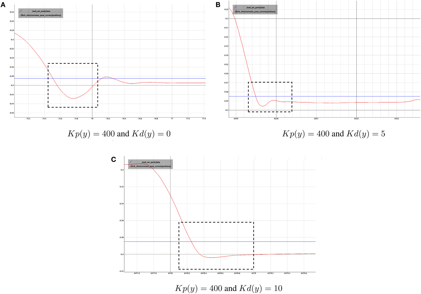
A plot of current MTM Position along y axis when interacting with a wall in the x, z plane located at y = 0.385 m. (A–C) show the controller performance for different values of Kp and Kd.
Table 1
| Gain parameters | Response time (s) | % Offshoot | Stead-state error (cm) |
|---|---|---|---|
| Kp = 400, Kd = 0 | 0.4 | 10.2 | 100 |
| Kp = 400, Kd = 5 | 0.5 | 1.27 | 15 |
| Kp = 400, Kd = 10 | 0.5 | 1.25 | 20 |
Test case of a wall in y direction.
Approximated values for controller performance for different values of Gain Parameters.
The work presented in this research relies heavily on ROS framework and node-based design. Each component is running independently as a ROS node and communicates with other nodes at different frequencies. The advantage of such a framework compared to other work in the field of haptics is the ability to scale the system to incorporate multiple master and slave arms. The node-based design is agnostic to the source of imaging for the environment. For the current scenarios, Kinect sensors are expected to be used for the point cloud of the environment as shown in Figure 2, but they could easily be replaced by any other imaging sensor that is capable of sensing the environment’s topology.
Srinivasan et al. (1996), Green and Salisbury (1997), Latimer (1997), and McNeely et al. (2005) focused on haptics before the advent of ROS or high speed computational machines. The use of node-based framework allows the use of a generic collision checking library to be incorporated for haptic feedback with little modification. The visualizations, in turn, are also enabled as separate nodes, which also provide an overlay of visual vectors in the direction of the experienced force. This visual information is helpful for debugging the algorithms and also enhance the user’s response. Li et al. (2015) demonstrates the use of visual cues as a PHF for the operator with interesting results. This study relies only on visual cues and not on force application. Thus, adding visual cues to actual haptic feedback is likely to enhance the haptic response.
The use actual master manipulators of a surgical robot (MTMs, in this case) also distinguishes the research from Baraff (1994), Green and Salisbury (1997), Talamini et al. (2003), Luk et al. (2006), and Ryden and Chizeck (2013) and several others, where commercially available haptic devices (from Phantom and Novint) were used. Although this research is demonstrated on the Master of the daVinci surgical robot, the presented mathematical models are generic to any serial or parallel manipulator. The node-based design of the control architecture has an advantage to this end as well. Of course, the underlying matrices and vectors would have to be evaluated for the specific manipulator for its use; however, these procedures are trivial and well covered in literature.
Although the results seem promising to begin with, there are several limitations to them and the procedure in general. These limitations can be generally classified into the qualitative analysis of the haptic feedback achieved, the choice of the SPR diameter with respect to the environment/task, and the limitations of the use of the current framework in actual surgery. Presently, the haptic feedback felt by the user has not been quantified. The feel would vary from user to user. A quantitative analysis would require additional hardware, including force/torque sensors at the master manipulator’s end, to measure the haptic response against the user’s preference. Luckily, there have been many studies done in this regard, some of which are discussed in Bennett et al. (1997), Okamura (2009), and Newman (1992).
Another limitation to the use of current stiffness control with gravitational compensation is that only the forces at the end-effector are considered. Although the use of end-effector moments are likely to enhance the haptic feel and awareness of the environment; Santos-Carreras et al. (2010) suggests that the inclusion of the end-effector moments do not enhance the task space performance by a noticeable margin. However, it should be noted that their findings were conducted with commercially available haptic devices. Apart from the inclusion of the end-effector moments, the current stiffness controller does not account for the inertial parameters involving the Coriolis and inertia matrix terms. The current assumption for simplification of the problem is that the operator would not induce large velocities or accelerations to the Master manipulator. These assumptions, although flexible, cannot be relied upon for general cases. Thus, it is paramount to consider the use of a full impedance controller rather than just a stiffness controller. The inaccurate estimate of most of the inertial parameters and the instability of the impedance controller are the biggest challenges to be overcome, if such a control scheme is implemented.
As discussed in the implementation details, FCL is being used for collision checking. Although FCL is very fast and responsive for collision checking, it is not tailored for haptic applications. As the research moves forward, a few modifications to the library might be required. These modifications emanate from the collision point averaging techniques used in the library. The averaging techniques serve to limit the number of collision checks performed and reported by the library. Occasionally, this results in instantaneous artifact forces in various directions. Although the occurrence is rare, it is attributed to the way collision checking has been implemented in FCL.
Last, the SPRs are modeled only at the tips of the PSMs. Thus, any collision of the shaft or the body of the slave manipulator with the environment is not reported. For MIS cases, this is certainly not a limiting factor. However, for a more realistic emulation, the entire body of the slave manipulator should be considered for collision checking. This is beyond the scope/focus of current research although affixing SPRs at various points other than just the end-effector can be considered for collision checking.
The next goal for complementing the control architecture for haptic feedback is the mounting of Polaris Optical Sensors and developing an automated procedure to register the PSMs, Kinect Sensors, and the World Frame to each other as shown is Figure 2. The stiffness response of the MTM is also an area of further improvement.
5 Discussion
This research presents the implementation of a haptic feedback framework for the master manipulator of a teleoperated surgical robot, demonstrated on the dVRK. The haptic feedback has two different components, the sensing of the operating environment to compute interaction deflection and then using this deflection to generate haptic forces. The first part of modeling, the interaction with the environment, is replicated using virtual environments. A novel idea for the contact of the slave manipulators with the environment has been presented that uses elastic SPRs. These SPRs are virtually mounted on the tip of the slave manipulators. This assumes that the contact of the slave manipulators and the operating environment only happens at the end-effector.
A node-based application for sensing and manipulation in the virtual environment has been developed. The application relies on MoveIt and FCL for collision checking. The FCL collision checking library is incapable of computing correct surface normals at contacts. The generation of normals for the operating environment using SPRs has been discussed. Due to the issues encountered with the computation of correct contact normals when the SPR slides along operating environments the use of the original algorithm is limited. This led to modifications of the original algorithm for generating contact normals. This has been discussed in Section 3.3.
Last, the haptic force exerted by the master manipulator to the users hand is achieved using stiffness control with gravity compensation. The choice of stiffness control over admittance and impedance control is discussed in Section 2.2. The stiffness controller results in a static interaction with the environment, and the perceived rigidity of the environment is controlled by changing the Kp and Kd gains. The effect of changing these gains is demonstrated in Section 4.
The overall goal of this research is the implementation of haptic feedback for existing and future robot-assisted laparoscopic platforms without the use of additional haptic devices. The algorithms and derivations are generic, which would allow expanding this research to platforms other than the daVinci Surgical Robot. The first part of haptic feedback implementation is the sensing of the environment, which presents a challenge for MIS. This challenge arises from the mounting complexities of force/torque sensors due to the size, design, and operating environment of the surgical manipulators. Using the novel SPR-based approach, however, the surgical environment is intended to be sensed using imaging sensors and then processed for haptic interaction. The other part of the haptic feedback framework that deals with the generation of haptic feedback forces on the master manipulator is generic as well. Although the proposed stiffness controller is tailored for the MTMs of the daVinci robot, the procedure can be generalized to any serial/parallel manipulator for surgical applications.
Statements
Author contributions
AM and GF have both contributed to the paper. GF has been responsible for the revision and approval of the paper along with providing guidelines for the research.
Conflict of interest
The authors declare that the research was conducted in the absence of any commercial or financial relationships that could be construed as a potential conflict of interest.
References
1
AvilaR. S.SobierajskiL. M. (1996). “A haptic interaction method for volume visualization,” in Visualization’96. Proceedings (Salt Lake City, UT: IEEE), 197–204.
2
BannS.KhanM.HernandezJ.MunzY.MoorthyK.DattaV.et al (2003). Robotics in surgery. J. Am. Coll. Surg.196, 784–795.10.1016/S1072-7515(02)01750-7
3
BaraffD. (1994). “Fast contact force computation for non penetrating rigid bodies,” in Proceedings of the 21st Annual Conference on Computer Graphics and Interactive Techniques (Orlando, FL: ACM), 23–34.
4
BasdoganC.HoC.SrinivasanM. A. (1997). “A ray based haptic rendering technique for displaying shape and texture of 3d objects in virtual environments,” in ASME Winter Annual Meeting, Vol. 61, 77–84.
5
BennettC. L.StrykerS. J.FerreiraM. R.AdamsJ.BeartR. W. (1997). The learning curve for laparoscopic colorectal surgery: preliminary results from a prospective analysis of 1194 laparoscopic-assisted colectomies. Arch. Surg.132, 41–44.10.1001/archsurg.1997.01430250043009
6
BetheaB. T.OkamuraA. M.KitagawaM.FittonT. P.CattaneoS. M.GottV. L.et al (2004). Application of haptic feedback to robotic surgery. J. Laparoendosc. Adv. Surg. Tech.14, 191–195.10.1089/1092642041255441
7
ButtoloP.OboeR.HannafordB. (1997). Architectures for shared haptic virtual environments. Comput. Graph.21, 421–429.10.1016/S0097-8493(97)00019-8
8
ChittaS.SucanI.CousinsS. (2012). Moveit![ROS topics]. IEEE Robot Autom Mag19, 18–19.10.1109/MRA.2011.2181749
9
ColgateJ. E.BrownJ. M. (1994). “Factors affecting the z-width of a haptic display,” in Proceedings of the IEEE International Conference on Robotics and Automation, 1994 (San Diego, CA: IEEE), 3205–3210.
10
CostaI. F.BalaniukR. (2001). “Lem-an approach for real time physically based soft tissue simulation,” in IEEE International Conference on Robotics and Automation, 2001. Proceedings 2001 ICRA. IEEE International Conference on, Vol. 3 (Seoul: IEEE), 2337–2343.
11
DaviesB.HibberdR.CoptcoatM.WickhamJ. (1989). A surgeon robot prostatectomy-a laboratory evaluation. J. Med. Eng. Technol.13, 273–277.10.3109/03091908909016201
12
DeguetA.KumarR.TaylorR.KazanzidesP. (2008). “The CISST libraries for computer assisted intervention systems,” in MICCAI Workshop on Systems and Arch. for Computer Assisted Interventions, Midas Journal, New York, NY.
13
EllisR.SarkarN.JenkinsM. (1996). “Numerical methods for the haptic presentation of contact: theory, simulations, and experiments,” in Proceedings of the ASME Dynamic Systems and Control Division, Vol. 58 (Atlanta, GA), 413–420.
14
GagnerM.BeginE.HurteauR.PompA. (1994). Robotic interactive laparoscopic cholecystectomy. Lancet343, 596–597.10.1016/S0140-6736(94)91546-6
15
GreenD. F.SalisburyJ. K. (1997). “Texture sensing and simulation using the phantom: towards remote sensing of soil properties,” in Proceedings of the Second PHANToM Users Group Workshop, Number 1617. AI Technical Report, Dedham, MA.
16
HagnU.NicklM.JörgS.PassigG.BahlsT.NothhelferA.et al (2008). The dlr miro: a versatile lightweight robot for surgical applications. Ind. Robot35, 324–336.10.1108/01439910810876427
17
HoganN. (1984). Adaptive control of mechanical impedance by coactivation of antagonist muscles. IEEE Trans. Automat. Contr.29, 681–690.10.1109/TAC.1984.1103644
18
JungM.XiaT.DeguetA.KumarR.TaylorR.KazanzidesP. (2009). “A surgical assistant workstation (saw) application for teleoperated surgical robot system,” in The MIDAS Journal-Systems and Architectures for Computer Assisted Interventions, New York, NY.
19
KazanzidesfP.ChenZ.DeguetA.FischerG. S.TaylorR. H.DiMaioS. P. (2014). “An open-source research kit for the da vinci® surgical system,” in IEEE International Conference on Robotics and Automation (ICRA), 2014 (Hong Kong: IEEE), 6434–6439.
20
KwohY. S.HouJ.JonckheereE. A.HayatiS. (1988). A robot with improved absolute positioning accuracy for CT guided stereotactic brain surgery. IEEE Trans. Biomed. Eng.35, 153–160.10.1109/10.1354
21
LatimerC. W. (1997). Haptic Interaction with Rigid Objects Using Real-Time Dynamic Simulation. Ph.D. thesis, Massachusetts Institute of Technology, Boston, MA.
22
LiM.KonstantinovaJ.SeccoE. L.JiangA.LiuH.NanayakkaraT.et al (2015). Using visual cues to enhance haptic feedback for palpation on virtual model of soft tissue. Med. Biol. Eng. Comput.53, 1177–1186.10.1007/s11517-015-1309-4
23
LukJ.PasqueroJ.LittleS.MacLeanK.LevesqueV.HaywardV. (2006). “A role for haptics in mobile interaction: initial design using a handheld tactile display prototype,” in Proceedings of the SIGCHI conference on Human Factors in Computing Systems (New York, NY: ACM), 171–180.
24
MarohnC. M. R.HanlyC. E. J. (2004). Twenty-first century surgery using twenty-first century technology: surgical robotics. Curr. Surg.61, 466–473.10.1016/j.cursur.2004.03.009
25
McNeelyW. A.PuterbaughK. D.TroyJ. J. (2005). “Six degree-of-freedom haptic rendering using voxel sampling,” in ACM SIGGRAPH 2005 Courses (Los Angeles, CA: ACM), 42.
26
NewmanW. S. (1992). Stability and performance limits of interaction controllers. J. Dyn. Syst. Meas. Control114, 563–570.10.1115/1.2897725
27
OkamuraA. M. (2004). Methods for haptic feedback in teleoperated robot-assisted surgery. Ind. Rob.31, 499–508.10.1108/01439910410566362
28
OkamuraA. M. (2009). Haptic feedback in robot-assisted minimally invasive surgery. Curr. Opin. Urol.19, 102.10.1097/MOU.0b013e32831a478c
29
PanJ.ChittaS.ManochaD. (2012). “FCL: a general purpose library for collision and proximity queries,” in IEEE International Conference on Robotics and Automation (ICRA), 2012 (St. Paul, MN: IEEE), 3859–3866.
30
PatelV.ChammasM.ShahS. (2007). Robotic assisted laparoscopic radical prostatectomy: a review of the current state of affairs. Int. J. Clin. Pract.61, 309–314.10.1111/j.1742-1241.2006.01235.x
31
RydenF.ChizeckH. J. (2013). A proxy method for real-time 3-dof haptic rendering of streaming point cloud data. IEEE Trans. Haptic.6, 257–267.10.1109/TOH.2013.20
32
RydenF.KosariS. N.ChizeckH. J. (2011). “Proxy method for fast haptic rendering from time varying point clouds,” in IEEE/RSJ International Conference on Intelligent Robots and Systems (IROS), 2011 (San Francisco, CA: IEEE), 2614–2619.
33
Santos-CarrerasL.BeiraR.SengülA.GassertR.BleulerH. (2010). Influence of force and torque feedback on operator performance in a vr-based suturing task. Appl. Bionics Biomech.7, 217–230.10.1080/11762322.2010.503110
34
SatavaR. M. (2003). Robotic surgery: from past to future – personal journey. Surg. Clin. North Am.83, 1491–1500.10.1016/S0039-6109(03)00168-3
35
SicilianoB.VillaniL. (2012). Robot Force Control. Napoli: Springer Science & Business Media, 540.
36
SrinivasanM. A.BeauregardG. L.BrockD. L. (1996). “The impact of visual information on the haptic perception of stiffness in virtual environments,” in ASME Winter Annual Meeting, Vol. 58 (New York, NY), 555–559.
37
TalaminiM.ChapmanS.HorganS.MelvinW. S.Academic Robotics Group. (2003). A prospective analysis of 211 robotic-assisted surgical procedures. Surg. Endosc.17, 1521–1524.10.1007/s00464-002-8853-3
38
TaylorR. H.FundaJ.EldridgeB.GomoryS.GrubenK.LaRoseD.et al (1995). A telerobotic assistant for laparoscopic surgery. IEEE Eng. Med. Biol. Mag.14, 279–288.10.1109/51.391776
39
The Economists Online. (2012). Surgical Robots: The Kindness of Strangers. Available at: http://www.economist.com/blogs/babbage/2012/01/surgical-robots
40
Westebring-Van Der PuttenE.GoossensR.JakimowiczJ.DankelmanJ. (2008). Haptics in minimally invasive surgery – a review. Minim. Invasive Ther. Allied. Technol.17, 3–16.10.1080/13645700701820242
41
WurdemannH. A.SeccoE. L.NanayakkaraT.AlthoeferK.LisK.MuchaL.et al (2013). “Mapping tactile information of a soft manipulator to a haptic sleeve in rmis,” in 3rd Joint Workshop on New Technologies for Computer/Robot Assisted Surgery (CRAS 2013). Verona.
42
ZhangZ.MunawarA.FischerG. S. (2014). “Implementation of a motion planning framework for the davinci surgical system research kit,” in The Hamlyn Symposium on Medical Robotics (London), 43.
Summary
Keywords
haptic feedback, stiffness control with gravity compensation, spherical proxy region, teleoperated surgical robots, cooperative control
Citation
Munawar A and Fischer G (2016) A Surgical Robot Teleoperation Framework for Providing Haptic Feedback Incorporating Virtual Environment-Based Guidance. Front. Robot. AI 3:47. doi: 10.3389/frobt.2016.00047
Received
06 April 2016
Accepted
20 July 2016
Published
09 August 2016
Volume
3 - 2016
Edited by
George P. Mylonas, Imperial College London, UK
Reviewed by
Luis Gomez, University of Las Palmas de Gran Canaria, Spain; Emanuele Lindo Secco, Liverpool Hope University, UK
Updates
Copyright
© 2016 Munawar and Fischer.
This is an open-access article distributed under the terms of the Creative Commons Attribution License (CC BY). The use, distribution or reproduction in other forums is permitted, provided the original author(s) or licensor are credited and that the original publication in this journal is cited, in accordance with accepted academic practice. No use, distribution or reproduction is permitted which does not comply with these terms.
*Correspondence: Adnan Munawar, amunawar@wpi.edu
Specialty section: This article was submitted to Biomedical Robotics, a section of the journal Frontiers in Robotics and AI
Disclaimer
All claims expressed in this article are solely those of the authors and do not necessarily represent those of their affiliated organizations, or those of the publisher, the editors and the reviewers. Any product that may be evaluated in this article or claim that may be made by its manufacturer is not guaranteed or endorsed by the publisher.